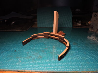
Matthew 1497 1:48 scale by Mike 41 [COMPLETED BUILD]

Well said, Mike. However, the way laser beam operates (when cutting the wood), makes an angeled cut. It is not just about removing the char, it is more to make a 90-degree side, I think. An extra wood most likely will suffice

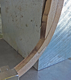
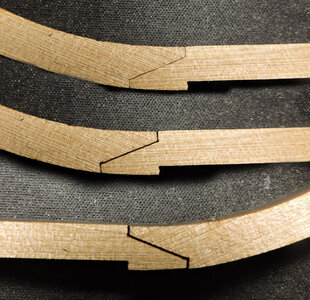
Jimsky is right about that angle from the laser cutting. The botton keel is one side and it is the side that was facing down on the cutting table and the focus of the beam spread out, when you flip it over ( the middle image you can see the parts fit tighter where the beam is focused. What i did was a little filing of the surfaces to get the final fit at the top.
If you use a darker wood like Cherry or Steamed pearwood the joinery will not stand out as much as using a light colored wood like Maple or Boxwood. You can fit the joinery tight or use a China Marker and caulk the joint.

keel6.jpg

With keel asembled i will jig up to test my fit of the frames

FRAME JIG1.jpg

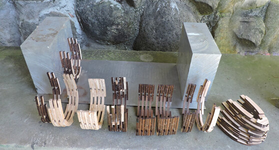
all the frames from 15 to midship and from midship to frame Q at the bow.

frame 15 sets at the end of the deadwood so i will line up the block

FRAME JIG3.jpg

at the bow i lined up the block with the end of the apron piece.

FRAME JIG2.jpg
 
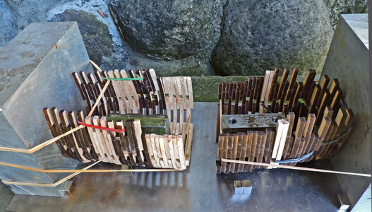
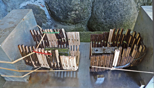
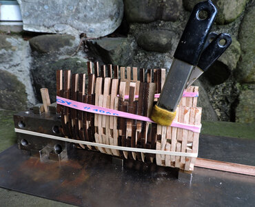
The idea here is to see if all the frames will fit between the two blocks. I glued up blocks of frames from 2 to 4 frames per block just incase i have to make side to side adjustments.

FRAME JIG4.jpg

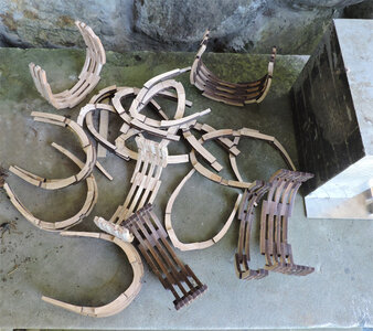
got all the frames in order and ready to assemble. The light colored frames are ones i had to make over because i messed some up.

FRAME JIG5.jpg

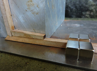
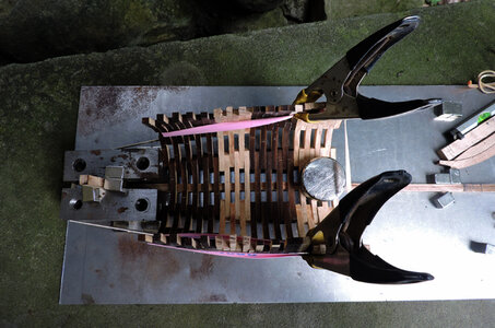
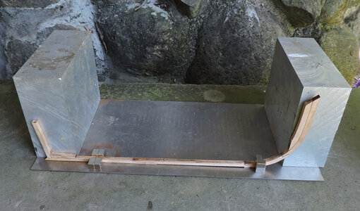
rubber bands, lead weights, one piece of sheet steel, two aluminum blocks and magnets make up my framing jig. Quite low tech nothing fancy but effective

FRAME JIG6.jpg

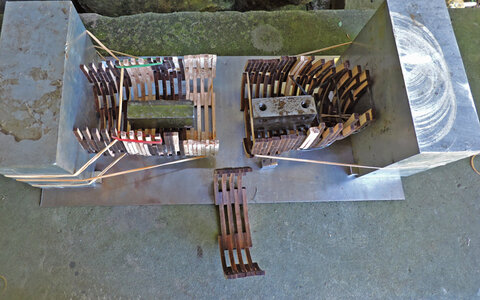
the last section will it fit?

FRAME JIG7.jpg

and the final answer NO it did not

FRAME JIG8.jpg

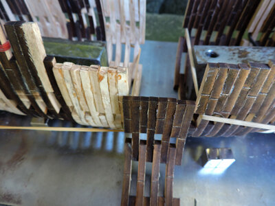
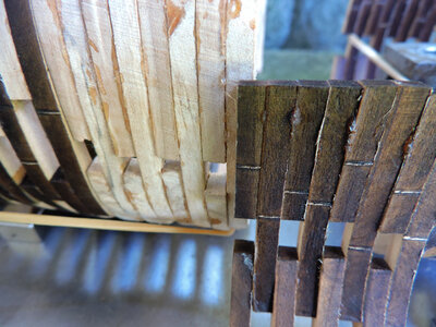
ooh! so close just 1/2 a timber off

FRAME JIG9.jpg

but i can do the happy dance i have nine blocks so all it will take is an ever so slight sanding of a few blocks and the hull will fall in between the blocks. If i fell short then i would have had to add shims.

FRAME JIG9.jpg

All righty then i will fit and finish the frames and then set up the keel and glue it all together.
 
Nice work on the frames Dave, I like your low-tech framing jig. Where did you pick up the aluminum blocks? I tried Home Depot, but they were out of stock.

I am getting close to finishing the main deck framing, will post something tomorrow.
 
Nice work on the frames Dave, I like your low-tech framing jig. Where did you pick up the aluminum blocks? I tried Home Depot, but they were out of stock.

I am getting close to finishing the main deck framing, will post something tomorrow.

i had those aluminum blocks around here for over 20 years
 
I found some on Amazon 3x3x8” for $60, I will use something else.
 
the ones i have are 7 x 7 x 3 and smaller ones 2 x 3 x 6 and 1 x 2 x 3

over the years they came in handy a number of times. I learned using jigs from a steel fabricator, Bill use to make all kinds of jigs out of scraps.

so when i first said i think this can be done without a jig well that is not exactly true because i am using jigging but not those fancy ones you are seeing theses day in new kits. By using steel blocks, sheet steel and rare earth magnets the configurations are endless.

I see two facets in the hobby those who strive to craft a work of art and the work of someone like Harold Hahn who took the craft to a fine art but it was a didactic art. I took the same path i am more interested in the how and why and the process and not so much the final results.

notice at the bottom of the blocks there are magnets holding the blocks in position. If these were steel blocks they would be held tight in place. Here the magnets are holding the aluminum block from moving.

FRAME JIG6.jpg
 
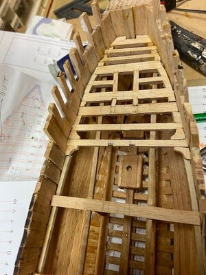
Main Deck Beams

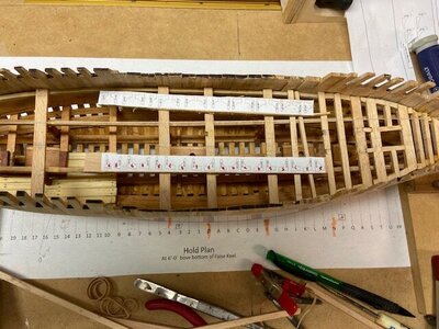
The single frames, lodging knees, and spacers were added next.
I managed to get a couple of carlings in bow crooked and had to replace them, some of the knees had to be trimmed also.

The stern framing is in progress.

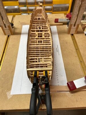
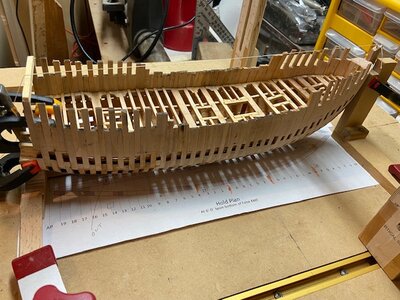
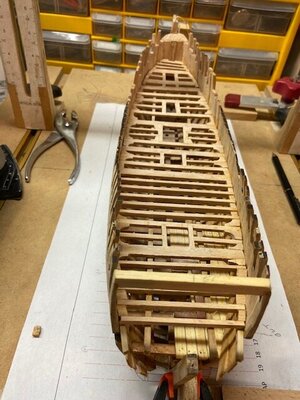
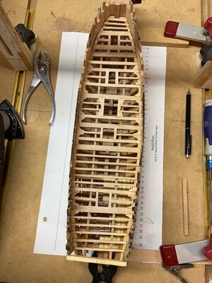
IMG_4032.jpgIMG_4033.jpgIMG_4034.jpgIMG_4036.jpgIMG_4037.jpgIMG_4038.jpgIMG_4040.JPGIMG_4043.jpg
 
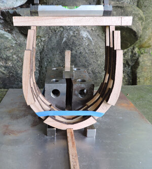
while Mike is building decks i am now going to assemble the hull. After a test fit of all the frames i am starting with frame block 15,14 and 13 at the stern.

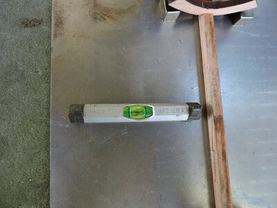
first i started with making sure i was level right to left and front to back.

FRAME JIG10.jpg

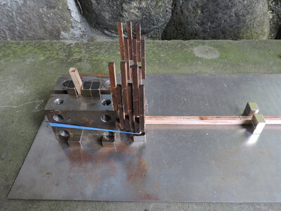
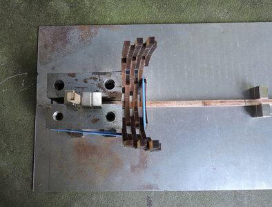
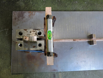
setting up a jig i am using steel machinist blocks. i am now using steel rather than aluminum because i want the magnets to stick to the blocks.
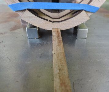
The set up is to sandwich the keel and stern post between the two blocks. The three magnets on top at the stern post are holding the keel from moving back or forward, magnets at the bottom are holding the blocks tight against the keel.

FRAME JIG11.jpg

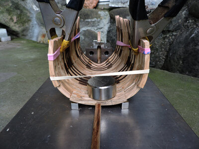
the blue high tech rubber band holds the frame block tight to the blocks.

FRAME JIG12.jpg

the frame blocks were built in my keel jig so i know the keel notches will all line up on the keel

DSCN1141.JPG

With the frame block secured to the machine blocks with a rubber band i know they are not leaning forward or backward. I also know the frames are at a 90 degree to the keel side to side.
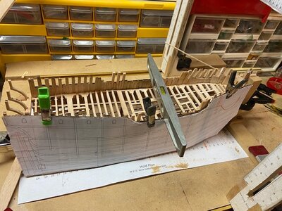
one more setting i need to confirm is the frame block sitting side to side. This is where the level comes in. Mike drew a line "top of frame" on each frame drawing, so as long as you placed the top timber on that line you know the frame is built the same on both sides of center.

FRAME JIG13.jpg

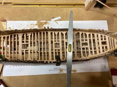
by placing a level on the top timbers you know that block of frames are right were they should be in all directions.


FRAME JIG14.jpg


i went ahead and place magnets under the floor on both sides of the keel. I so when i remove the frames to apply glue i can replace them in the exact same position. These magnets are so strong you can not pick them up off the steel plate so you know once you are setup nothing is going to shift.

FRAME JIG15.jpg

what makes this project interesting is the build and not so much spending hours and hours milling out wood and cutting out parts. It also is showing a totally different approach to jigging up a hull.
 
what makes this project interesting is the build and not so much spending hours and hours milling out wood and cutting out parts. It also is showing a totally different approach to jigging up a hull.

It is interesting to see how this project developed from not using plans or jigs to Dave’s method of using magnets and a drawing or two creating a highly accurate model and a versatile reusable low-cost jig.

I have used magnets for frames and small deck items, but they were not strong enough to do what Dave is using them for. I ordered some of the super magnets from Amazon today, they are about a $1.00 each and expect to use them on my next project

Thanks Dave, see you can teach an old dog new tricks lol.
 
while Mike is building decks i am now going to assemble the hull. After a test fit of all the frames i am starting with frame block 15,14 and 13 at the stern.

first i started with making sure i was level right to left and front to back.

View attachment 320457

setting up a jig i am using steel machinist blocks. i am now using steel rather than aluminum because i want the magnets to stick to the blocks.
The set up is to sandwich the keel and stern post between the two blocks. The three magnets on top at the stern post are holding the keel from moving back or forward, magnets at the bottom are holding the blocks tight against the keel.

View attachment 320458

the blue high tech rubber band holds the frame block tight to the blocks.

View attachment 320459

the frame blocks were built in my keel jig so i know the keel notches will all line up on the keel

View attachment 320464

With the frame block secured to the machine blocks with a rubber band i know they are not leaning forward or backward. I also know the frames are at a 90 degree to the keel side to side.
one more setting i need to confirm is the frame block sitting side to side. This is where the level comes in. Mike drew a line "top of frame" on each frame drawing, so as long as you placed the top timber on that line you know the frame is built the same on both sides of center.

View attachment 320460

by placing a level on the top timbers you know that block of frames are right were they should be in all directions.


View attachment 320461


i went ahead and place magnets under the floor on both sides of the keel. I so when i remove the frames to apply glue i can replace them in the exact same position. These magnets are so strong you can not pick them up off the steel plate so you know once you are setup nothing is going to shift.

View attachment 320462

what makes this project interesting is the build and not so much spending hours and hours milling out wood and cutting out parts. It also is showing a totally different approach to jigging up a hull.
If you wanted to make sure things were level you could borrow Jimsky's little ball thing a ma bob for checking level from his last tease posting.
 
I have used magnets for frames and small deck items, but they were not strong enough to do what Dave is using them for. I ordered some of the super magnets from Amazon today, they are about a $1.00 each and expect to use them on my next project


it would take 70 pounds of pull strength to lift these frames. Notice the chips, that is from the magnet slamming into other things.
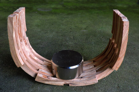
MAG IN FRAME2.jpg

this is the size i am using as a jig. stuck to the bed plate it takes about 30 pound pull force, but because there is wood between the bed plate and the magnet the force is reduced.
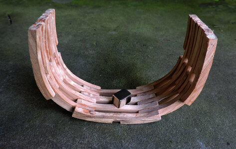
MAG IN FRAME1.jpg


these come in strengths from N35 to N52 and depending on size their pull strength will vary from 19 pounds to 75 pounds and up

Magnet pull strength is the highest possible holding power of a magnet,. It is the force required to pull a magnet away from a flat steel surface when the magnet and metal have full and direct surface-to-surface contact. The grade of the metal, surface condition and angle of pull all have an impact on the pull strength.

mag1.JPG

this little 3/4 inch cube has a strength of 75 pounds

mag2.JPG

pull strength 19 pounds


mag3.JPG

strength 35 pounds

Magnet Safety
Neodymium magnets must be handled with care to avoid personal injury and damage to the magnets. Fingers and other body parts can get severely pinched between two attracting magnets. Bones can be broken by larger magnets.
Neodymium magnets are brittle. They can peel, crack or shatter if allowed to slam together. Eye protection should be worn when handling these magnets, because shattering magnets can launch pieces at great speeds and sparks may be produced.
The strong magnetic fields of neodymium magnets can also damage magnetic media such as floppy disks, credit cards, magnetic I.D. cards, cassette tapes, video tapes or other such devices. Electronics such televisions, VCRs, computer monitors and other CRT displays can also be damaged.
Children should not be allowed to play with neodymium magnets as they can be dangerous. Small magnets pose a choking hazard and should never be swallowed or inserted into any part of the body.
Never allow neodymium magnets near a person with a pacemaker or similar medical device. The strong magnetic fields of the magnets can affect the operation of such devices.
Neodymium magnets are brittle and prone to chipping and cracking. Machining, drilling or other mechanical alterations are not recommended.
Neodymium magnets will begin to lose their magnetic properties if heated above 176° F (82° C).
The Bottom Line: Like any tool, neodymium magnets can be useful and educational, but must always be treated with care.

 
Last edited:
Stern Framing

7/28/2022 4047 48 – 51

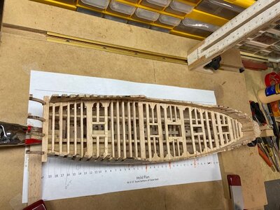
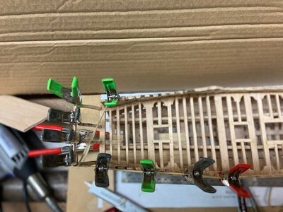
I did not enclose the stern with the frames and deck beams to have better access to the hanging knees and other items under the deck.

The first step was making sure the stern was square and level. I installed the helm port transom and stern counter timbers. As shown in the progress photos.
IMG_4047.jpgIMG_4048.jpgIMG_4049.jpgIMG_4050.jpgIMG_4051.jpg
 
Thanks Ken, we have had a few problems, but overall, the project is going well.
 
nice work Mike i would think i am a slacker because i am only 1/2 way building the hull and you are doing the deck and stern. But actually Mike is blazing the trail ahead of me and i am following Mikes trail avoiding problem or pit falls along the trail and showing even the first time plank on frame builder you can build this model. There are many creative way to build a ship model.

anyhow i am at midship and so far so good. By the way those pink high tech rubber bands are available at your locat grocery store in the produce dept. they hold things like heads of broccoli together

FRAME JIG17.jpg

birds eye view notice the big magnet

FRAME JIG16.jpg


that is acting as my level i can level the hull by shifting the magnet to one side or the other. The little magnets are stuck to the bed plate and the big magnet pulls on the small ones. The hull will remain level as i go forward with the framing. Not only does the hull have to be level with the bed plate but you have to maintain level between frame blocks to avoid a twist in the hull. Believe me things like a twist creep up on you and start out small but end up being a problem.

FRAME JIG18.jpg


Great progress Mike. Such an interesting ship. You and Dave make a great team!
it is a dynamic team effort and the results are two styles of model building. Mike is actually building a historic model of a ship, i am building a proof of concept a prototype for a future Ships of Scale building project. So with me avoiding all the finish work of a piece of maritime art Mike and I might end up close at the finish line. Besides i am itching to work on the next project.
 
nice work Mike i would think i am a slacker because i am only 1/2 way building the hull and you are doing the deck and stern.
Thanks Dave, you must have forgotten finishing the Tecumseth while I was fumbling around with my frames lol. You are making good progress with your frames and with a little sanding they will look great (maybe a lot of sanding at the bow).

Stern Framing
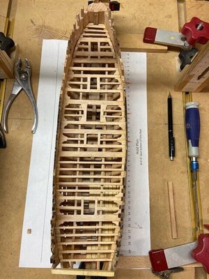
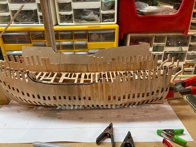
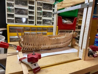
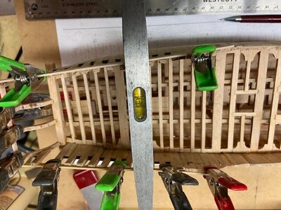
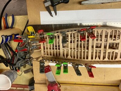
I thought it would be a good time to check the frames height and make any adjustments if required. I used a copy of the interior profile to make a cardboard template. I clamped the template to the hull and using a Dremel with a sanding drum lowered the high spots and extended a few low ones.

This is a few photos of the process.
IMG_4058.jpgIMG_4059.jpgIMG_4060.jpgIMG_4061.jpgIMG_4062.jpg
 
Thanks Dave, this type of framing is not as complex as a warship, it does not have to deal with the weight and recoil of a bunch of canons. I did not get to use my gantry much, but the base did a good job holding the hull in place lol.
 
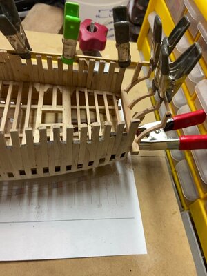
Stern Framing

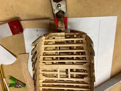
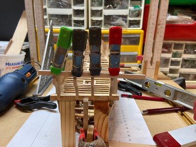
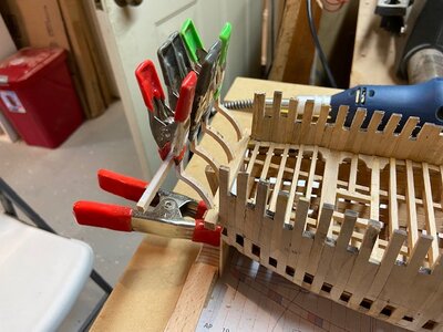
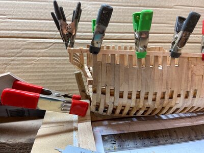
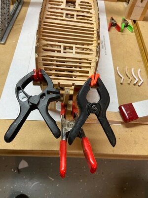
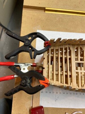
While waiting for some glue to dry I am posting some progress photos. I was thinking a square a square stern would be easier to plank, but all the photos I could find shows it rounded with the side planking ending at the stern post so that’s what we are going to have.
The next post will not have all the clamps covering up all the work lol.


IMG_4063.jpgIMG_4063.jpgIMG_4064.jpgIMG_4065_Moment.jpgIMG_4066.jpgIMG_4067.jpg
 
Back
Top