Matthew 1497 1:48 scale by Mike 41 [COMPLETED BUILD]

YES MIKE AND THANK YOU DAVE FOR THE KIND WORDS BUT THERE MAYBE A REMEDY CHECK OUT THE MINERVA BUILD BY DA HAI AND BRIANS BUILD LOG HE HAS A JIG DESIGNED TO BE USED ON OTHER BUILDS WITH SOME MODIFICATIONS LET ME KNOW WHAT YOU THINK. GOD BLESS STAY SAFE YOU AND YOURS DON
 
Main Deck

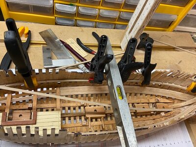
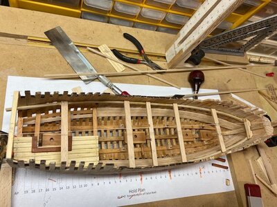
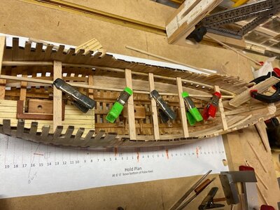
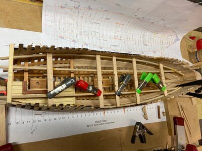
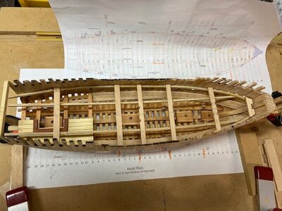
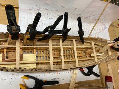
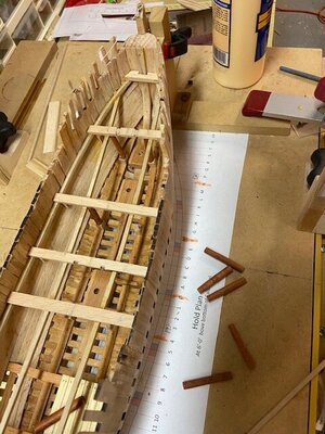
The main deck clamps consist of the main clamp, lodging knees, chocks between beams and two strakes below the clamp. There are no carlings between the beams. The beams are also supported by two strongback strakes and pillars.

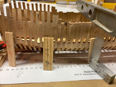
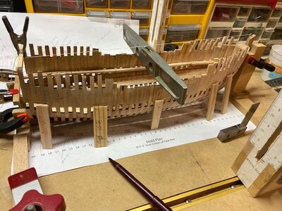
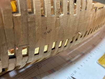
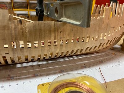
I normally mark the height of the deck clamps inside the hull using the space between frames, this style does not have those spaces. I made sure the hull was level and marked the top of the clamps on the outside of the hull and drilled .08mm holes for 18-gauge copper wire pins. I glued the clamps in place clamping them below the pins as shown in the following photos.

IMG_3999_Moment.jpgIMG_4001.jpgIMG_4003.jpgIMG_4004.jpgIMG_4005.jpgIMG_4006_Moment.jpgIMG_4007_Moment.jpgIMG_4008.jpg
 
Looking good Mike. I have just purchased the Lively by the Lumberyard, and will commence that kit soon.

Thanks Bryian, I am looking forward to your build log for the Lively. It looks like the Minerva is keeping you busy.
 
Main Deck Beams

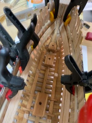
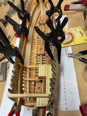
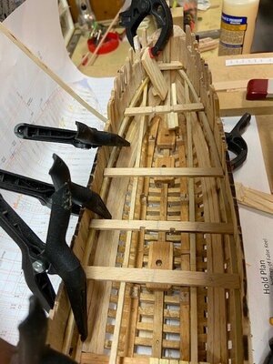
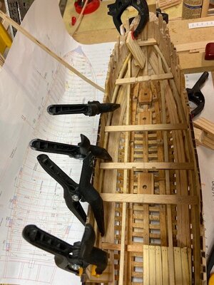
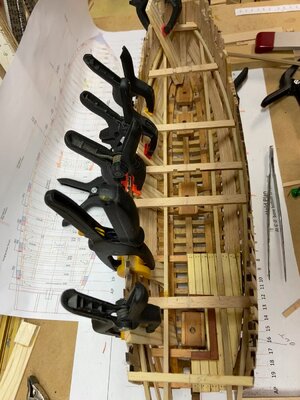
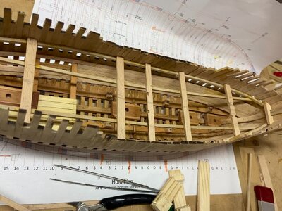
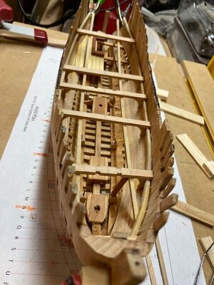
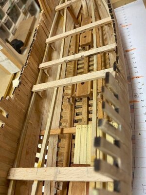
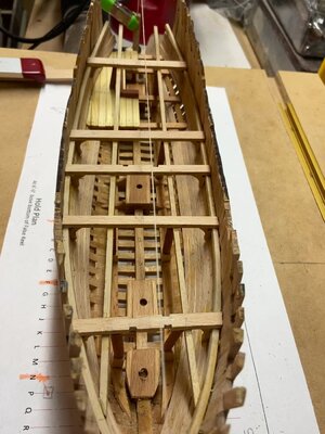
There are five double wide beams that sit on two strongback timbers with pillars from strakes in the hold. These beams have lodging and hanging knees, the hanging knees are centered below the beams. These beams are installed first and the strongback glued below, this will facilitate fitting the hanging knee and pillars.

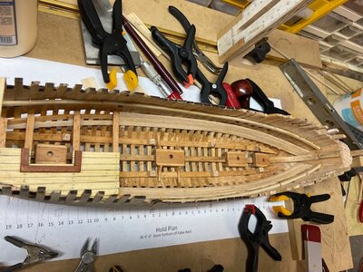
The first photo shows the five double in place followed by the strongbacks. The internal hold lining was done next, it would have been easier if done before the beams were installed, but prototyping is a learning process lol. The hanging knees and pillars under the strongbacks were added next.

IMG_4009.jpgIMG_4010.jpgIMG_4011.jpgIMG_4013.jpgIMG_4014.jpgIMG_4015.jpgIMG_4016.jpgIMG_4017_Moment.jpgIMG_4018_Moment.jpg
 
Nice progress, guys! Will plans be available for a full scratch build as well as a timbering set? I think this is a really unique and interesting build!


i think the plan is to make available a timbering set, a rigging package, plans and drawings. Right now everything is at 1:48 scale.
 
i have finished with building frames and now ready to move on to the keel assembly.

Mast and Capstan Steps

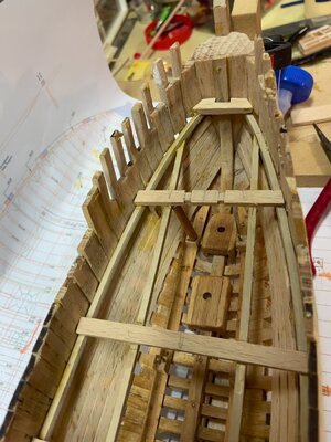
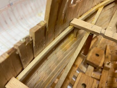
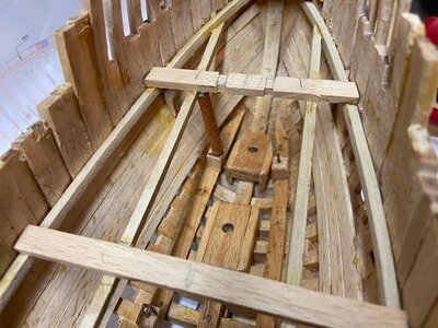
The design for the steps was based on the Canadian replica. A straightforward design that is working. I used magnets to assemble the steps the main mast has a pair of knees reinforcing the sides of the step the other steps are not reinforced. I drilled 1/8” diameter holes in the steps to set the masts, not historically accurate but works for the model. Progress photos.


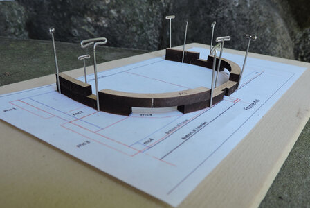
before moving on to the keel Mike gave me a good idea about magnets. This is how i started assembling frames by pinning the parts in place.
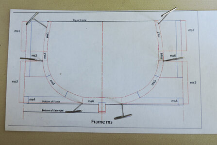
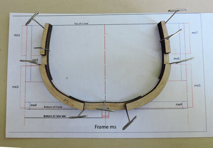
A1.jpgA2.jpgA3.jpg

then i thought of a piece of sheet steel and Neodymium magnets (rare earth magnets)
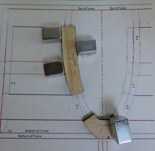
mag1.jpgmag2.jpg

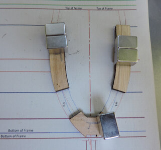
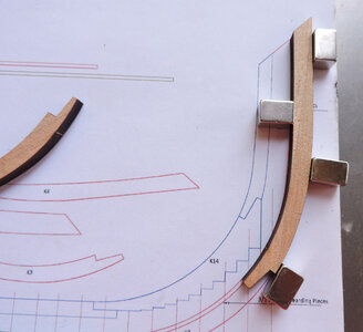
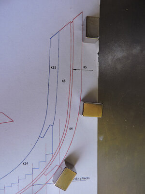
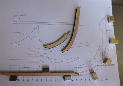
these magnets are so strong they hold the pieces tight in place, I tried both ways by putting magnets on the piece and lined them up with the drawing. You can actually flip the sheet upside down and wave it in the air and those parts are stuck in place. You can not pull two magnets apart , you have to carefully slide them apart.

What makes the build so accurate is because the parts are cut exactly to the drawings. As long as you build the frame to the drawings everything should come together. I hope

I did scrap 7 frames by gluing them together wrong so i had to scroll saw new parts out and sand them to the shape of the drawing. As long as you take your time and shape the parts to the drawing you can't wander that far off the build.
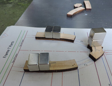
mag3.jpg

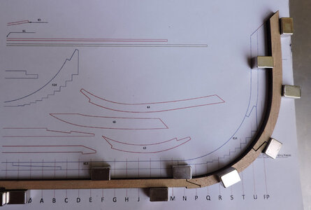
setting up the keel i am placing the magnets along the drawing to wedge the parts in place. To adjust the joinery i need to lift the piece out and then place it back in the exact same spot. A tricky job setting up a jig with rare earth magnets, they just don't attract to each other, they slam themselves together.
mag5.jpg

mag4.jpg

mag6.jpgmag7.jpg
 
Last edited:
First i layed out all the parts from the laser sheet

keel1.jpg

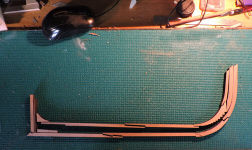
then i assembled the parts where they should go, i left the computer mouse in the picture so you can get an idea of the model size.

.keel2.jpg

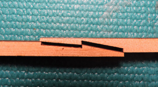
All the joinery will need a little adjusting, you can see here the scarfs are a tiny bit long.

keel3.jpg

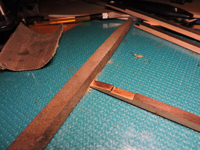
it does not take much, just a few passes along a file or sanding block

keel4.jpg

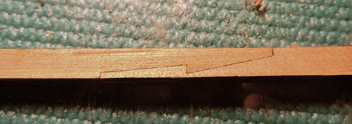
and the two pieces should fit nice and clean.

keel5.jpg
 
Last edited:
That may be the cleanest scarf joint I've seen in a kit. The axial timbers, in general look very good.
 
That may be the cleanest scarf joint I've seen in a kit. The axial timbers, in general look very good.

i do not want to mislead any future builders the scarf did not come that way it was tweeked to fit. A tiny bit of sanding with a file on the mating surfaces removed some char and produced a flat fitting surface.
 
Last edited:
Yes, the photos prior to sanding and of it being sanded explicitly shows some work is required. However the overage prior to sanding also shows how little sanding effort is required to achieve a great join.
 
Back
Top