Matthew 1497 1:48 scale by Mike 41 [COMPLETED BUILD]

This is how a team of 2 work Mike shows me this drawing. The concept 1 actually we do not know exactly how the stem of the Matthew was built so this was taken as a historic general example.
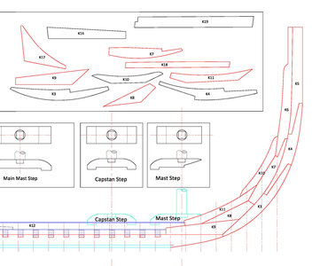
stem1.jpg

i say YIKES! that is nice and well, maybe a bit complex to assemble. complex joinery may be a focus in out next project but not this one.

at an early stage i guess we were not sure of deadwood which we later found out there is no deadwood.

and a redesign in part based on what can be done with a laser.
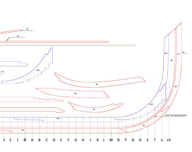
stem2.jpg
 
if i were to set up the cutting files to cut right on Mikes lines the .012 beam is vaporizing the material the width of the red line

joinery3.JPG

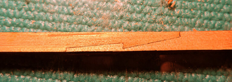
looking close the blue part hook of the scarf is smaller than the original and the yellow part where the hook fits into is bigger resulting in a loose fit.


joinery2.JPG
 
so how is joinery done

with offsets setting up a cutting path you can get joinery almost perfect. Joinery off the laser will not fit and that is done on purpose. YOU have to do the final fit.

ANGLE3.jpg

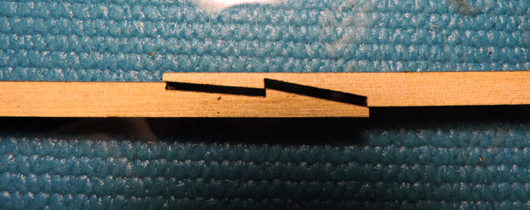
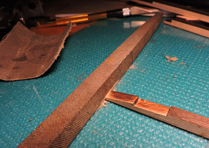
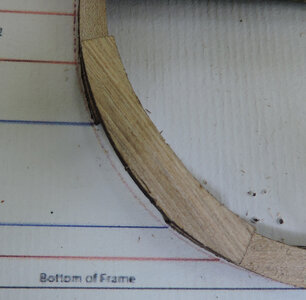
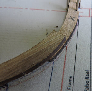
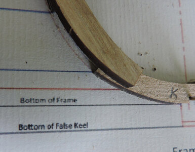
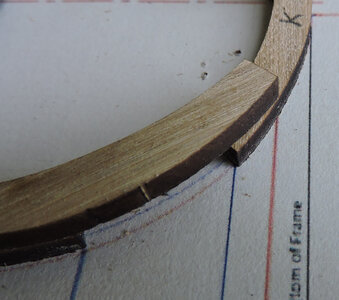
for the hook scarf in the keel a cutting path is set up to over cut the ends and a path for the faces. What i did was scrape the faces with a razor blade, i didn't scrape them clean, just enough to remove that little rise down the center you remember that little rise in post #139

ANGLE5.jpg

and a clean tight fit

ANGLE4.jpg
 
the frame cutting files are setup to give a builder a little + or - when assembling the frames and hull.
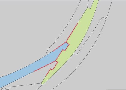
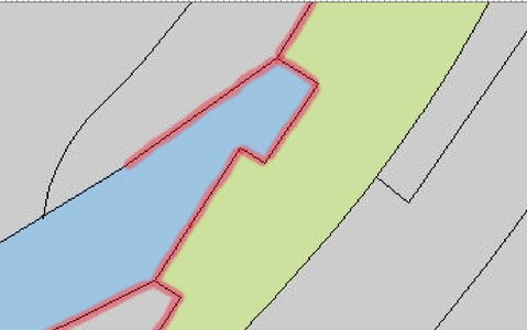
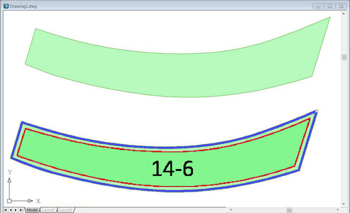
the red line is Mikes original drawing of the part the lighter line around the red is .015 all around, the actual cutting file is the blue line. Kind of like the wooden Russian doll that fits one in another. The char is the blue so removing that you still have more material to finalize the shape.

so your part looks like the light green piece


offset1a.jpg
 
Last edited:
I guess the gap between parts would be too wide to use for caulking. Some builders go to great lengths to outline the joints.
 
I guess the gap between parts would be too wide to use for caulking. Some builders go to great lengths to outline the joints.

a builder might want to try the China Marker i used for the deck caulking on the Tecumseth.

also light colored wood like West Indian Boxwood would make the joinery stand out as apposed to darker woods like Cherry.
 
so how is joinery done

with offsets setting up a cutting path you can get joinery almost perfect. Joinery off the laser will not fit and that is done on purpose. YOU have to do the final fit.

View attachment 316927

for the hook scarf in the keel a cutting path is set up to over cut the ends and a path for the faces. What i did was scrape the faces with a razor blade, i didn't scrape them clean, just enough to remove that little rise down the center you remember that little rise in post #139

View attachment 316929

and a clean tight fit

View attachment 316928
Dave, I'm sorry, I understand that there is a dimensional rule on the sculls, I can't see on Your photo you posted, is it the photo? Thanks

e.jpg
 
Dave, I'm sorry, I understand that there is a dimensional rule on the sculls, I can't see on Your photo you posted, is it the photo? Thanks

View attachment 316937

someone help Frank out i don't understand the post. There are a lot of different scarfs the Matthew is a simple standard version. There are also ones that use a round stop water, hooks and box scarfs
 
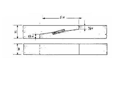
Hi Frank, the proportional rule for a scarf joint is based on the width of the board (H). The ends of the scarph are one third of the width of the board (1/3H) and the horizontal length of the scarph is five times (5H) the width of the board (H), Dave is using a modified version for the hook scarf.
 
someone help Frank out i don't understand the post. There are a lot of different scarfs the Matthew is a simple standard version. There are also ones that use a round stop water, hooks and box scarfs
Dave, I think @Frank48 Francesco talking about the specific sizes in the scarf, rather than the type of scars. but I could be wrong...
 
still building frames and taking notes

note

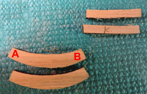
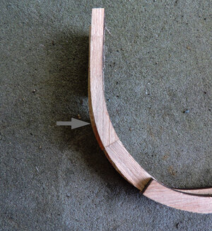
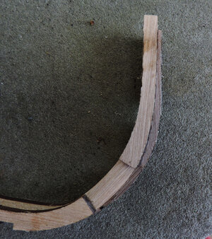
i noticed many of these frame parts look the same, does end A or B lap over the floor? one way is to lay the parts on the drawings and mark them

J0.jpg

What i see as i built when the right end is on the floor you get a match up of the edges

J2.jpg

the arcs are the same

J3.jpg


if you get the part turned around you get this the arc does not match up so fip it around.

J4.jpg
J1.jpg
 
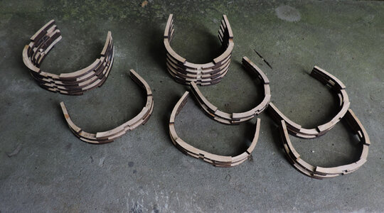
the more i build the better i like the model. This one your watching is a prototype, my thinking it is a small model 14 1/2 inches 355mm delicate looking with all the open framing, close tolerance building. I just migh break away from "done with the prototype" and do another final model out of West indian Boxwood, a historic ship, framed built to historical data. Maybe do 10 sets of parts hum thats 100 sheets a lot of boxwood, maybe a limited edition.

oh were was i frame K back to it then
 
It would be helpful to piece mark the frames using the pattern drawings before removing the parts from laser sheets, save a little time and head scratching during the frame assembly.
 
i built each frame to the drawing then paired up two frames and stacked two pairs.

K1.jpg
you have to be accurate in building each frame as you reach the bow and stern the frames change shape. You can see the frame below is wider so you have to center the frame above so it is the same on bother sides of center.K3.jpgK2.jpg

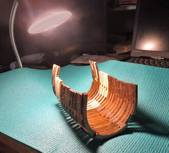
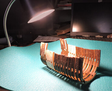
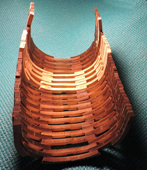
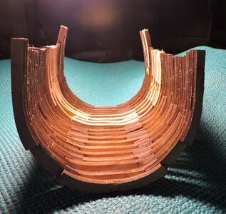
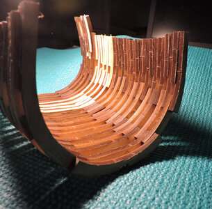
i lined up all the blocks of four frames to see if i am getting some sort of hull shape and if the blocks are lining up with each other.

K7.jpgK8.jpg

i was a little concerned the blocks of 4 frames would vary in width but they are lining up.

K5.jpg

the hull is loosly sitting on glass and everything is coming together

K4.jpgK5.jpgK6.jpg
 
QUESTION ARE THE TOLARANCES TO EXACT FOR THE AVERAGE BUIKDER? GOD BLESS STAY SAFE YOU AND YOURS DON

not really as long as you build each frame to Mikes drawing you should be just fine. Over all the frames are bigger than the finished size so there is a built in tolerance of a 1/32 to allow for assembly of the frames and hull.
This build is more about the building and not having to accuratly cut out all the parts, that part is done for you.
Now, if you are building from scratch and not using the laser cut parts then that is an added step that will require you to accuratly cut out all the frame parts.
 
OK GOT IT DAVE NO WAY FOR ME TO SCRATCH BUILD THIS ONE. GOD BLESS STAY SAFE YOU AND YOURS DON

i would not say no way to scratch build it you are an accomplished model builder, but using the laser cut parts gives a builder a huge advantage.
 
Back
Top