
Thanks Dave! I still have a bit left over so unless I start over for a third time I should be ok. I think it’s just my inexperience in being more selective of the defects natural to any wood For modeling. I have built a lot of furniture, curio boxes, clocks, etc and these minuscule defects are never an issue. Lesson learned!Oliver there should be enought material to be selective if not i will send more and i will be more selective or at least the best i can. Sometimes mother nature just does what she wnts.

You are using an out of date browser. It may not display this or other websites correctly.
You should upgrade or use an alternative browser.
You should upgrade or use an alternative browser.
Le Rochefort build log by OlivierF
- Thread starter OlivierF
- Start date
- Watchers 21
-
- Tags
- ancre group build le rochefort
Today I rebuilt the shipyard and confirmed top and bottom are true plumb, level and square. The keel assembly fits as it should and I’m continuing to verify that the frame floors fit the slots in the rising wood.
so far so good…


I’m going to wait to cut the slots in the keelson until I’ve completed the frames and attached them to the keel.
so far so good…
I’m going to wait to cut the slots in the keelson until I’ve completed the frames and attached them to the keel.

This looks very promising, good jig. A little tip try to screw the keel to the bottom plate of your shipyard, because when you start gluing the frames your keel will lift fore and aft. I asked a carpenter why this happens, his answer was: It happens because of the moisture in the glue, the wood works at this point and dries faster than the wood, thus creating tension in the direction of the wood grain. Due to the glue, the wood cannot go back at this point after it is dry and you get this curvature.
Very good progress! ")

Interesting Tobias. This would explain what happened to me when I glued on the false keel (the pearwood strip on the bottom):This looks very promising, good jig. A little tip try to screw the keel to the bottom plate of your shipyard, because when you start gluing the frames your keel will lift fore and aft. I asked a carpenter why this happens, his answer was: It happens because of the moisture in the glue, the wood works at this point and dries faster than the wood, thus creating tension in the direction of the wood grain. Due to the glue, the wood cannot go back at this point after it is dry and you get this curvature.
I ended up with a keel that had a humpback in the center that I have been fighting back into place...
Thanks Tobias.This looks very promising, good jig. A little tip try to screw the keel to the bottom plate of your shipyard, because when you start gluing the frames your keel will lift fore and aft. I asked a carpenter why this happens, his answer was: It happens because of the moisture in the glue, the wood works at this point and dries faster than the wood, thus creating tension in the direction of the wood grain. Due to the glue, the wood cannot go back at this point after it is dry and you get this curvature.
I have ordered some m3 threaded inserts that should fit the keel. If they do I will bolt the keel to the building board and subsequently use the inserts to mount the finished model.
Here the attachment to the ground and the keel


Thanks Tobias.
what size threaded insert did you use? The M3 size I ordered uses a 17/64” drill bit which is 6.75mm so it won’t work. I ordered actual wood inserts from Amazon M3 insert-link. I think you are using 3D printer inserts but I couldn’t find your posting.
Hi Oliver, I also used M3. Here is the link to my post with the link from Amazon.Thanks Tobias.
what size threaded insert did you use? The M3 size I ordered uses a 17/64” drill bit which is 6.75mm so it won’t work. I ordered actual wood inserts from Amazon M3 insert-link. I think you are using 3D printer inserts but I couldn’t find your posting.
Post in thread 'LE ROCHEFORT - Harbour yacht from 1787 1:36 by Tobias (Monograph by ANCRE)'
https://shipsofscale.com/sosforums/...y-tobias-monograph-by-ancre.10941/post-306597
Thank you!Hi Oliver, I also used M3. Here is the link to my post with the link from Amazon.
Post in thread 'LE ROCHEFORT - Harbour yacht from 1787 1:36 by Tobias (Monograph by ANCRE)'
https://shipsofscale.com/sosforums/...y-tobias-monograph-by-ancre.10941/post-306597
I canceled my earlier order and ordered just the M3 inserts and appropriate drill bit… Well, a set of metric drill bits as I only have SAE bits.
Today, (again, following Tobias’ advice) I inserted 3 each m3 anchors to the bottom of the keel. One in the middle, one at reference 3 and other at reference 29. I haven’t mounted the axial assembly to the building base yet as I’m trying to figure out how to make sure I mount the keel so the frame references on the templates line up. Maybe I’ll wait until the frames are assembled but before glueing them onto the keel. To be determined…


I also spend the day making the wing transom. I think I built it correctly and I dry fitted it to the sternpost. A question I have is, how to make sure the wing transom is correctly positioned on the sternpost. Currently I raised the frame support up to the level of the wing transom and am using the plan outline to make sure the transom is square and level to the keel but there is really no reference on canting the transom fore and aft. Should I build the counter frames and fit them to the transom and then line them up to to plans? Any suggestions from you more experienced folks?


I also spend the day making the wing transom. I think I built it correctly and I dry fitted it to the sternpost. A question I have is, how to make sure the wing transom is correctly positioned on the sternpost. Currently I raised the frame support up to the level of the wing transom and am using the plan outline to make sure the transom is square and level to the keel but there is really no reference on canting the transom fore and aft. Should I build the counter frames and fit them to the transom and then line them up to to plans? Any suggestions from you more experienced folks?
Last edited:
I haven’t completed a lot today as I spent much of my hobby time reviewing the transom pieces and trying to work out the proper curves. Once I got started cutting the pieces I realized that Adrian was incorrect when he said that these pieces are the same thickness as the frames. They are not 5.3mm thick. They are 4.5mm thick (6 pouce) based on the scantlings reference in the Monograph (Page 86) and physical measurement of the plans. Anyway, once I sanded them down to the correct thickness they dry fit on the stern post very well. Tomorrow I’ll work on the fashion pieces for the sides of the transoms.


Thank you very much for bringing this up.
This will help me to avoid problems when I will work on the transom timbers.
Maybe you should mention this information also in the general blog of the A.N.C.R.E. Le Rochefort Group Build:
"Start-up Conversations" and "Build Support-Tips, Advice" here.
This will help me to avoid problems when I will work on the transom timbers.
Maybe you should mention this information also in the general blog of the A.N.C.R.E. Le Rochefort Group Build:
"Start-up Conversations" and "Build Support-Tips, Advice" here.
Good point Dieter. I’ll write it up and post it in ”Build Support” Later this morning.Thank you very much for bringing this up.
This will help me to avoid problems when I will work on the transom timbers.
Maybe you should mention this information also in the general blog of the A.N.C.R.E. Le Rochefort Group Build:
"Start-up Conversations" and "Build Support-Tips, Advice" here.
- Joined
- Mar 1, 2022
- Messages
- 246
- Points
- 113

Awsome! Keel and ribs look absolutely perfect! I like the shipyard master's figure as well. Where could I get anything similar? Thanks in advance!
Hello albertmary,Where could I get anything similar?
Similar figures are now available at ancre.fr. They just introduced them some days ago.
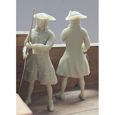
Personnage XVIII - Ancre
 ancre.fr
I ordered already one for my build
Thank You Albertmary for your encouraging words. As Dieter said you can order them from Ancre but I 3D printed my architect figure.Awsome! Keel and ribs look absolutely perfect! I like the shipyard master's figure as well. Where could I get anything similar? Thanks in advance!
- Joined
- Mar 1, 2022
- Messages
- 246
- Points
- 113
Wow, congrats. Very well done!Thank You Albertmary for your encouraging words. As Dieter said you can order them from Ancre but I 3D printed my architect figure.
- Joined
- Mar 1, 2022
- Messages
- 246
- Points
- 113
Oh, thank you so much, Nersch!Hello albertmary,
Similar figures are now available at ancre.fr. They just introduced them some days ago.
Personnage XVIII - Ancre
I ordered already one for my build
Today I worked on assembling the transom Timbers. I think I did them correctly and mounted them to the stern post. I also carved the fashion pieces and believe I made those correctly as well. However, I cannot for the life of me figure out how they get assembled to each other. I’ve looked at Adrian’s book and supplemental pictures. Check @Tobias and other builds for further reference… I guess I’ll go have a beer and come back tomorrow. Maybe they will make sense then,
