You are using an out of date browser. It may not display this or other websites correctly.
You should upgrade or use an alternative browser.
You should upgrade or use an alternative browser.
Le Rochefort build log by OlivierF
- Thread starter OlivierF
- Start date
- Watchers 21
-
- Tags
- ancre group build le rochefort
I’m very pleased… I got one frame (no. 15) completed, shaped and sanded. And the dry fit appears to be perfect. I’ll move on to making the rest of the frames. I have to force myself to go slow because as Tobias and others have advised you really do need to be perfect as a 0.01mm deviation seems to compound quickly…
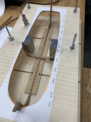
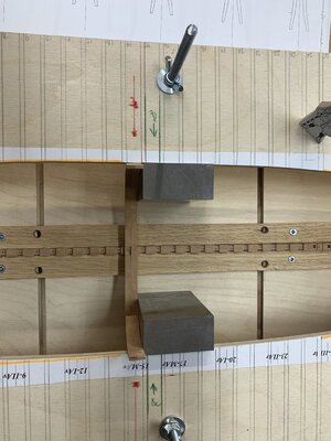
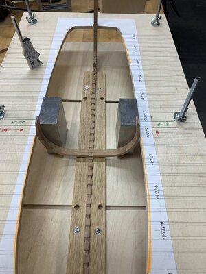
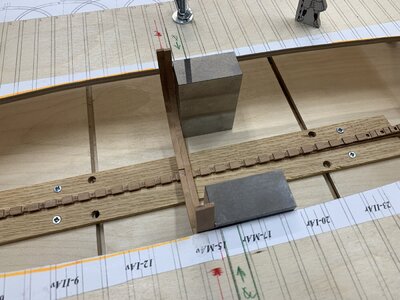


Looking good.
Hi Oliver very good progress and clean work.
Building the frames is going slowly. I’ve tried different methods in building each one up. I chose to scrap the modified Hahn method as it became a challenge to try and route the slots for the keel and keelson. I have also tried the way Adrian does it in the book which is similar to the way Tobias did it in his excellent tutorial. At the moment I’m using a blended method of Adrian’s and Tobias’ methods. Still not really happy with the results but I’ll keep practicing…
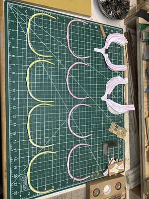
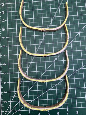


Hi Oliver, this really doesn't look bad. A mix of different methods certainly works well and in the end every way is okay. Everyone should do what is easiest and best for them. Thanks again for your praise I am flattered. What I notice and probably causes you problems is your sanding down to almost the actual shape of the frames before gluing them together. For comparison, here are pictures of how much wood I have left over after gluing the joints. This creates these differences in your joints and the halves of the frames.
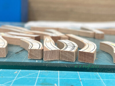
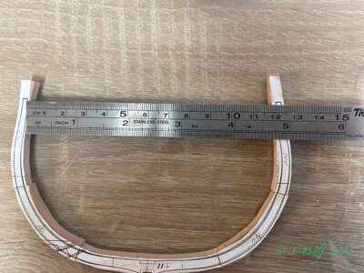
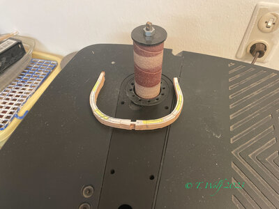


Thanks Tobias. i will leave a wider margin on my next set of frames per your suggestion.Hi Oliver, this really doesn't look bad. A mix of different methods certainly works well and in the end every way is okay. Everyone should do what is easiest and best for them. Thanks again for your praise I am flattered. What I notice and probably causes you problems is your sanding down to almost the actual shape of the frames before gluing them together. For comparison, here are pictures of how much wood I have left over after gluing the joints. This creates these differences in your joints and the halves of the frames.
View attachment 357650
View attachment 357648
View attachment 357649
Super Oliver, I am convinced that you will get a much better result. You have the advantage of having more material available and thus get a clean transition between the joints. My tip, which I have also done with La Palm, do not sand to the line but leave about 1mm of material to be able to compensate for slight unevenness in the outer line later.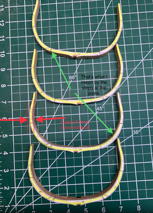
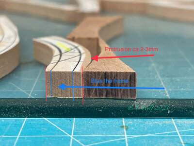
Here again is an example of what I mean by more overhang, it gives us the ability to adjust everything to create even transitions.
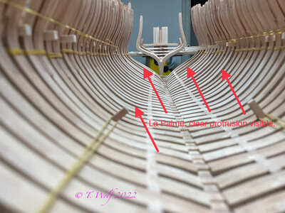
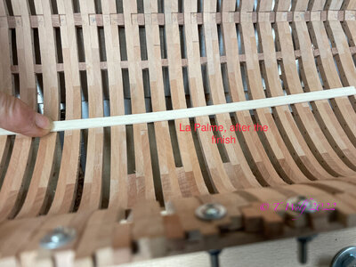


Here again is an example of what I mean by more overhang, it gives us the ability to adjust everything to create even transitions.


You're making process that’s good. Frames no matter the method take a very long time to do. Don’t rush, you’ll get there.
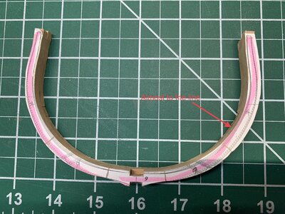
Well, I’m still struggling to get the frames to work out. I’ve tried making a few more but still not happy with the results. A question for those more knowledgeable (Basically everyone)... how to you get the “A” side and “B” sides to line up. As you can see in the below picture, the yellow side has a ways to go to get to the layout line while the pink side is at the inner layout line. I’ve made sure the floor sections are lined up as well as the bulwark ends. Also usEd Tobias’ method of measuring the ends to the plans (which are spot on), the middle sections continue to be out of plane. Any recommendations on how to get things to line up? 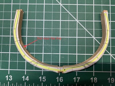


- Joined
- Nov 23, 2021
- Messages
- 79
- Points
- 113

hello Olivier, I can only tell you how I did it. I've been in this situation too. I sanded everything back to the lines with the spindle sander on the inside of the ribs. I consistently took the yellow shaded side for this and tried to get the width as equal as possible. There is a lot of chamfering on the red side, the latter gives you some room in the editing.
maybe Tobias has a better tip or idea
maybe Tobias has a better tip or idea
Last edited:
Thanks Splinter. If I understand correctly, basically you ignored the layout lines on the red side and used both the solid and dashed lines from the yellow side?hello Olivier, I can only tell you how I did it. I've been in this situation too. I sanded everything back to the lines with the spindle sander on the inside of the ribs. I consistently took the yellow shaded side for this and tried to get the width as equal as possible. There is a lot of chamfering on the red side, the latter gives you some room in the editing.
- Joined
- Nov 23, 2021
- Messages
- 79
- Points
- 113

I didn't use the dotted line just the solid lines, the dotted lines are for chamfering and that will come when the frames are sanded to the right shape. But please wait for a response from Tobias, he has more experience with this, I'm just a beginner and I sometimes do things by feel.Thanks Splinter. If I understand correctly, basically you ignored the layout lines on the red side and used both the solid and dashed lines from the yellow side?
Thanks again for your insight. Without Tobias and others it would be the blind leading the blind.I didn't use the dotted line just the solid lines, the dotted lines are for chamfering and that will come when the frames are sanded to the right shape. But please wait for a response from Tobias, he has more experience with this, I'm just a beginner and I sometimes do things by feel.
Hi Oliver, I faced the same problem with my first frames I built at La Palme.
Well Splitter has actually already given the right answer. We have the frame XY, which consists of two halves and each half of 5-7 individual parts, which we have glued together as best we can. There will always be differences between the two frames so you should choose one of the two halves as the main frame. In my case it is always the yellow frame that I use as a guide. Concentrate on just one side and then sand it to just before your outside line. Ignore the other side, because the basic shape is achieved (no matter what the pink side looks like). In the next step you come to the bevels inside and outside, chamfer them only slightly and leave about 0.5mm before the lines so you still have the possibility to make adjustments later. The final finish is done when all frames are glued with key and Keelson.
Use the frame shown in the picture above and sand the yellow side to just before the line and place it on your plan to check how well it fits.
Because we leave some overhang on the frame, you should of course also make sure that your jig is about 1mm bigger, otherwise you run the risk that the frames will squeeze and be bent inwards.
I hope I could help. Stand gladly at your disposal if something is still unclear
Translated with www.DeepL.com/Translator (free version)
Thanks again Tobias. I’ll proceed as you suggest. I know I do tend to overthink things and look for perfection. I guess it’s the engineer in me…Hi Oliver, I faced the same problem with my first frames I built at La Palme.
Well Splitter has actually already given the right answer. We have the frame XY, which consists of two halves and each half of 5-7 individual parts, which we have glued together as best we can. There will always be differences between the two frames so you should choose one of the two halves as the main frame. In my case it is always the yellow frame that I use as a guide. Concentrate on just one side and then sand it to just before your outside line. Ignore the other side, because the basic shape is achieved (no matter what the pink side looks like). In the next step you come to the bevels inside and outside, chamfer them only slightly and leave about 0.5mm before the lines so you still have the possibility to make adjustments later. The final finish is done when all frames are glued with key and Keelson.
Use the frame shown in the picture above and sand the yellow side to just before the line and place it on your plan to check how well it fits.
Because we leave some overhang on the frame, you should of course also make sure that your jig is about 1mm bigger, otherwise you run the risk that the frames will squeeze and be bent inwards.
I hope I could help. Stand gladly at your disposal if something is still unclear
Translated with www.DeepL.com/Translator (free version)
Agree, sand all the frames perfectly to just outside the line, the paper template will give you frames which are exactly the correct size and shape.
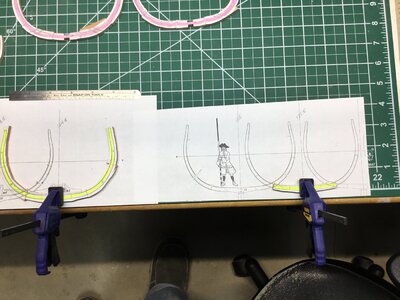
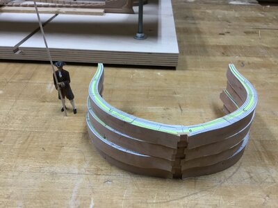
You know that old saying, “practice makes perfect.” Well, certainly not perfect but getting better… some mentioned that they like the IT reference of version numbers, so here we are at version 3.0 for the frames. I think I’m getting there. I’ve been using the frame drawings as underlayment for gluing the frames and it seems to work for me. I’m also using Tobias’ recommendation of measuring the tip of the frame against the end of the plan. So far they are looking more presentable. I also played with the 3D printer and made “The Architect”. I still need to make the scale on his staff but playing around with other things keeps me from getting frustrated.


Last edited:
Frames look great. Smart move scrapping the Hahn method. Wish I did too. There are no shortcuts and as well as I know that I'm always looking for them !


