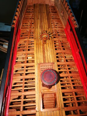
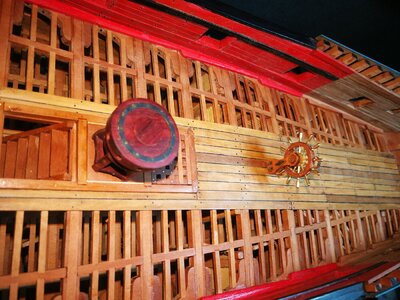
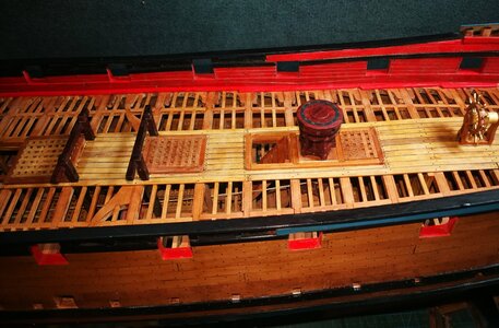
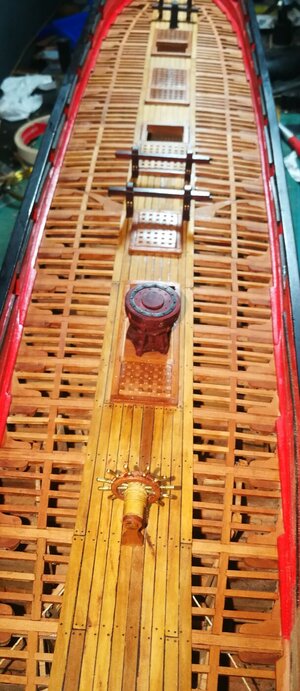
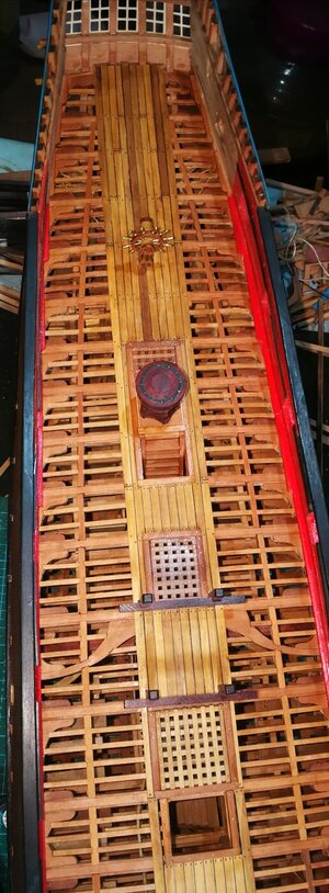
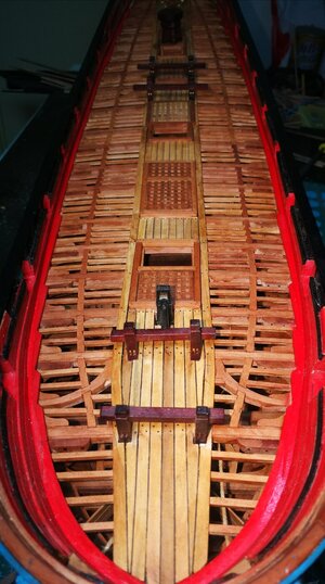
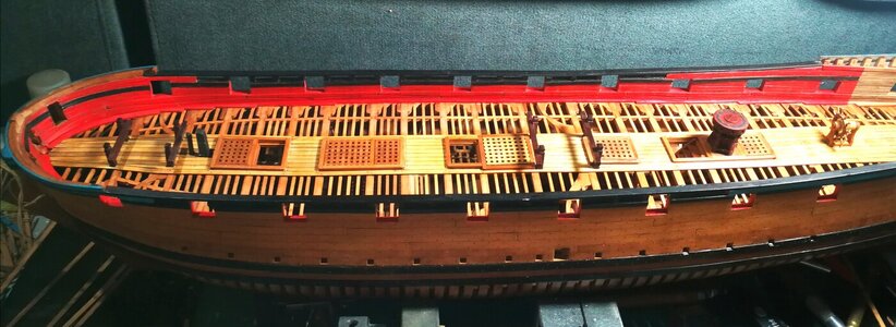
Thank you for your compliment, I'm sorry to reply some late. Didn't understand what you said "Fillers" refers to what is, on the ship's nails is real is not marked, with 0.6 mm ebony and fishing line 0.5 mm and 0.4 mm.Love your work
Interestingly you have dropped the "Fillers" below the main line of the body of the hull
Also yopuve "pinned" the Thick tuff to the side and bottom of the hull is that actually or marked - looks good what did you use
Wjhen I built my San Filepe and Victory i made tree nails out of 1mm square stuff (wood) rounded through a few holes in am old tobacco tin
You are using an out of date browser. It may not display this or other websites correctly.
You should upgrade or use an alternative browser.
You should upgrade or use an alternative browser.
HMS Blandford 1720 in scale 1:48 by Modelship Dockyard [COMPLETED BUILD]
- Joined
- Jul 24, 2016
- Messages
- 96
- Points
- 78

the fillers are at the top of the hull joining each of the frames. THey seem to drop well below the top off the frameThank you for your compliment, I'm sorry to reply some late. Didn't understand what you said "Fillers" refers to what is, on the ship's nails is real is not marked, with 0.6 mm ebony and fishing line 0.5 mm and 0.4 mm.
I am still "Filling" this part of the hl and I am makiing sure each "Filler" is as marked on the drawings so i can trim the frames to the correct height
I thought i had made a mistake
How did you get on with the Hawse Frames there seems to be a arge gap between the rear Hawse FRame and the No 1 Main (Square) FRame if you build them the way the little jig is designed
KEEP UP THE GREAT WORK - What did you use to get that great finish on the Keel parts please
the fillers are at the top of the hull joining each of the frames. THey seem to drop well below the top off the frame
I am still "Filling" this part of the hl and I am makiing sure each "Filler" is as marked on the drawings so i can trim the frames to the correct height
I thought i had made a mistake
How did you get on with the Hawse Frames there seems to be a arge gap between the rear Hawse FRame and the No 1 Main (Square) FRame if you build them the way the little jig is designed
KEEP UP THE GREAT WORK - What did you use to get that great finish on the Keel parts please
Because I am use translation software and you communicate, in the process of dialogue, because translation software can cause many places don't understand, you'd better put your problem in the image, to facilitate understanding. "Filler" means that I think you said why I let it above the frame at the top of the problems, "Filler" just model designers in order to strengthen the strength of the model, to ensure that the correct hull shape for building and add, testing result will not, so the installation position of "Fille" is not a problem. The image below should be very good, why do I make it more a problem of frame.
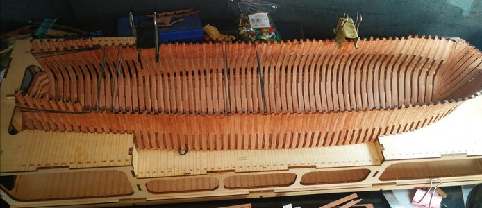
Because the model framework in the installation process will be a lot of reasons make the framework produces deformation, outward the hull frame deformation, the higher part of the rubber strip can be set as the anchor point, pull the inside of the hull deformation outward to the right position, fixed the hull deformation, of course, there are many other methods, this method is only my own habit, but I think this is the most simple way.
To the problem of the height of the frame can measure each frame in the suite drawings in the distance between the top to bottom, and then the height of the map in the model framework for cutting, the location of the "Filler" cannot be used as a reference frame height.
Because of my suite is in earlier time bought from the model, the designer, when I buy the suite and the suite of provided drawings have some problems, so I didn't use the drawings in the suite in building models, to a large number of reconstruction of the suite, I my suite this suite and everyone will have a lot of different, I mainly refer to the Goodwins books and original drawings of the boat to build.
- Joined
- Jul 24, 2016
- Messages
- 96
- Points
- 78

Language i s a problem
The Fillers, as you say, are the small pieces between the top of the hull
Your photos above are great and as they are designed
your earlier phots seemed to show them lower
I am not sure what you mean by "Suite" do you mean Your Model
Very Impressed with your work
THanks
The Fillers, as you say, are the small pieces between the top of the hull
Your photos above are great and as they are designed
your earlier phots seemed to show them lower
I am not sure what you mean by "Suite" do you mean Your Model
Very Impressed with your work
THanks
- Joined
- Oct 17, 2020
- Messages
- 1,336
- Points
- 393

Ciao Wang scusa una domanda, queste strisce lungo le travi sono di Kit? GrazieLa lingua è un problema
I Filler, come dici tu, sono i piccoli pezzi tra la parte superiore dello scafo
Le tue foto sopra sono fantastiche e come sono state progettate
le tue foto precedenti sembravano mostrarle più basse
Non sono sicuro di cosa intendi per "Suite", intendi il tuo modello
Molto impressionato dal tuo lavoro
Grazie
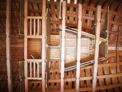
Last edited:
Hi ,this Wang’s build logHello Richard, excuse a question, are these strips along the beams from Kit? Thank you
View attachment 334118
- Joined
- Oct 17, 2020
- Messages
- 1,336
- Points
- 393

Thanks ZolyHi ,this Wang’s build log
What you see is a slightly different color of wood.Ciao Wang scusa una domanda, queste strisce lungo le travi sono di Kit? Grazie
I guess these beams are made out of three elements in sandwich-construction
a wider core element (lighter color) and on both sides thinner side-elements with the pre-cut recesses for the carlings
a different method to produce the recesses without using cnc, only laser-cut parts for the beams
Last edited:
- Joined
- Oct 17, 2020
- Messages
- 1,336
- Points
- 393

Ciao Wang, scusa una domanda, queste strisce lungo le travi sono di Kit? GraziePoiché io uso il software di traduzione e tu comunichi, nel processo di dialogo, poiché il software di traduzione può causare molti posti non capiti, faresti meglio a mettere il tuo problema nell'immagine, per facilitare la comprensione. "Filler" significa che penso che tu abbia detto perché l'ho lasciato sopra il telaio nella parte superiore dei problemi, "Filler" solo modellisti per rafforzare la forza del modello, per garantire che la forma dello scafo corretta per la costruzione e aggiunga , il risultato del test non lo farà, quindi la posizione di installazione di "Fille" non è un problema. L'immagine qui sotto dovrebbe essere molto buona, perché lo rendo più un problema di cornice.View attachment 333818
Poiché la struttura del modello nel processo di installazione avrà molte ragioni per cui la struttura produce deformazione, verso l'esterno la deformazione del telaio dello scafo, la parte superiore della striscia di gomma può essere impostata come punto di ancoraggio, tirare la deformazione all'interno dello scafo verso l'esterno per la giusta posizione, fissata la deformazione dello scafo, ovviamente, ci sono molti altri metodi, questo metodo è solo una mia abitudine, ma penso che questo sia il modo più semplice.
Per il problema dell'altezza della cornice si può misurare ogni cornice nella suite disegni nella distanza tra l'alto e il basso, e quindi l'altezza della mappa nel quadro del modello per il taglio, la posizione del "Riempimento" non può essere utilizzata come altezza del quadro di riferimento.
Poiché la mia suite è stata acquistata in precedenza dal modello, il progettista, quando acquisto la suite e la suite di disegni forniti hanno alcuni problemi, quindi non ho utilizzato i disegni nella suite nei modelli di costruzione, in gran numero di ricostruzione della suite, io la mia suite questa suite e ognuno ne avrà molte diverse, mi riferisco principalmente ai libri di Goodwins e ai disegni originali della barca da costruire.
Thanks Uwek, I guess it's Kit fixed, right?What you see is a slightly different color of wood.
I guess these beams are made out of three elements in sandwich-construction
a wider core element (lighter color) and on both sides thinner side-elements with the pre-cut recesses for the carlings
a different method to produce the recesses without using cnc, only laser-cut parts for the beams
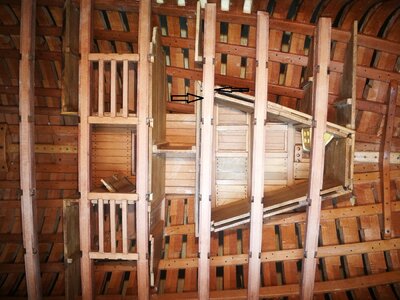
- Joined
- Jul 24, 2016
- Messages
- 96
- Points
- 78

nHi ,this Wang’s build log
just amazing - not sure how much is included in the kit wowView attachment 304380View attachment 304381View attachment 304382View attachment 304383View attachment 304384View attachment 304385View attachment 304386View attachment 304387View attachment 304388View attachment 304389View attachment 304391View attachment 304392View attachment 304393View attachment 304394View attachment 304395View attachment 304396View attachment 304398
- Joined
- Apr 20, 2020
- Messages
- 5,163
- Points
- 738

wonderful work, it's looks beautifulCiao Wang, scusa una domanda, queste strisce lungo le travi sono di Kit? Grazie
Thanks Uwek, I guess it's Kit fixed, right?
View attachment 334120

- Joined
- Jan 10, 2022
- Messages
- 467
- Points
- 323

That is exactly right Uwek. The centre section is 4 mm and the 2 outer sections with the cut outs fro the carlings are both 1 mmWhat you see is a slightly different color of wood.
I guess these beams are made out of three elements in sandwich-construction
a wider core element (lighter color) and on both sides thinner side-elements with the pre-cut recesses for the carlings
a different method to produce the recesses without using cnc, only laser-cut parts for the beams
Thanks ZolyHi ,this Wang’s build log
Thank you very much for your instructions, he is completely correct. You of the ship itself and the model in the production of knowledge are very comprehensive, let a person admire.What you see is a slightly different color of wood.
I guess these beams are made out of three elements in sandwich-construction
a wider core element (lighter color) and on both sides thinner side-elements with the pre-cut recesses for the carlings
a different method to produce the recesses without using cnc, only laser-cut parts for the beams
Yes, these are provided in the kit material, as mentioned Uwek and Keef, beam is composed of three parts separately material, need you to put them together.Ciao Wang, scusa una domanda, queste strisce lungo le travi sono di Kit? Grazie
Thanks Uwek, I guess it's Kit fixed, right?
View attachment 334120
- Joined
- Oct 17, 2020
- Messages
- 1,336
- Points
- 393

Hi Wahg, Thanks for answering me, Good modeling, FrankYes, these are provided in the kit material, as mentioned Uwek and Keef, beam is composed of three parts separately material, need you to put them together.
- Joined
- Jul 24, 2016
- Messages
- 96
- Points
- 78

not sure what you mean fishing line surely that is clear or transparent. surely it would not showThank you for your compliment, I'm sorry to reply some late. Didn't understand what you said "Fillers" refers to what is, on the ship's nails is real is not marked, with 0.6 mm ebony and fishing line 0.5 mm and 0.4 mm.
black fishing line - google itnot sure what you mean fishing line surely that is clear or transparent. surely it would not show
- Joined
- Jul 24, 2016
- Messages
- 96
- Points
- 78

thanksblack fishing line - google it

