HI HEINRICH, WILL START FRAME NO. 8 TOMORROW HAVE MY PINS AND COPIES READY YOU WILL SEE WHAT I MEAN BY PINS, QUESTION WHAT ARE THE CUTTING LINES AND DO YOU MARK ON THE FRAMES THE LOCATIONS. GOD BLESS STAY SAFE YOU AND ANNA DON
- Home
- Forums
- Ships of Scale Group Builds and Projects
- Bluenose PoF Group Build
- Bluenose Group Build Logs
You are using an out of date browser. It may not display this or other websites correctly.
You should upgrade or use an alternative browser.
You should upgrade or use an alternative browser.
YES I TEND TO AGREE BUT DO NOT HAVE THE EXPERTISE TO SAY IT, I DO AGREE WITH YOU AND DON ABOUT THE BEVELING WILL DO IT BY HAND AS SUGESTED AND HAVE TO COME UP ABOUT HOW TO DO THE FINISHING PLENTY OF TIME FOR THAT, GOD BLESS STAY SAFE YOU AND ANNA DON
- Joined
- Oct 12, 2019
- Messages
- 110
- Points
- 78

Good early morning,
That bluenose looks like a beautiful kit. I have never built a wooden ship before but have been a carpenter/woodworker for a good portion of my 44 year work life. I would like to purchase one, and with your site and members help, I know I will find success.
How would I go about purchasing the kit?
Thank you for any direction in this.
Steviedean.
- Joined
- Oct 12, 2019
- Messages
- 110
- Points
- 78

By the way,
I have flirted with building ship kits, at least acquiring kits;
3 by Artesania Latina
7 by model shipway's
( I also have around 300 balsa aircraft kits & 50'ish plastic kits plus too many tools & supplies)
Less than 3 years until retirement, hopefully I can whittle down those numbers abit.
What are some general opinions on the scale fidelity and quality of model shipway's kits?
Thanks again,
Steviedean
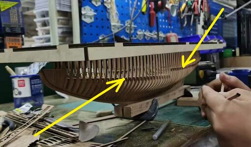
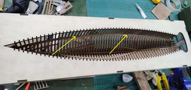
Hi,Don I'm not sure what they mean by "cutting lines". It would seem to me that those markings indicate the position of the beams as indicated by the yellow arrows on the pics below.
View attachment 201485
View attachment 201486
I suppoost you can see the cutting and the cutting lines on sheet 8-1, fig.19. With some tekst + “1 cm”.
Heinrich can translate the tekst.
In fig.17 and 18 the lines are also drawn.
Regards, Peter
Hey @Steviedean , have a look through many of the forums. There is one about model ship kit manufacturers. There are others that talk about scale. Myself I prefer 1/64 scale as it is large enough for detail to be evident but small enough that it gives me room to display. There are also lots of miniature figures available in this scale, in the event you want to add them to your builds.nI'll be trying this in my next build.By the way,
I have flirted with building ship kits, at least acquiring kits;
3 by Artesania Latina
7 by model shipway's
( I also have around 300 balsa aircraft kits & 50'ish plastic kits plus too many tools & supplies)
Less than 3 years until retirement, hopefully I can whittle down those numbers abit.
What are some general opinions on the scale fidelity and quality of model shipway's kits?
Thanks again,
Steviedean
HI STEVIEDEAD,THIS IS JUST MY OPION I HAVE DONE QUITE A FEW M/S KITS, EXCEPT FOR A FEW NEW ONES IE, PHILADELPHIA GUNBOAT, PICKET BOAT, THE REST ARE 30 TO 40 YEARS OLD NOTHING NEW WITH THEM JUST OLD WAYS AND VCERY OLD SUBJECTS, AS A NOTE GO TO MODEL EXPOS SITE NOW THEY ARE PROMOTING NEW ITEMS PLASTIC, UGEARS ETC NO NEW SHIP KITS CAN NOT COMPETE WITH PRICE, QUALITY ETC OF THE CINEESE OR RUSSIAN KITS, THEY HAVE JUST ONE THING NEW AS A SERIES OF KITS COMING OUT BY DAVID A, FROM BEGINNER TO MORE ADVANCED I LIKE THEM AS FILL INS AND GIFTS BUT THAT IS IT JUST MY 2 CENTS. GOD BLESS STAY SAFE YOU AND YOURS DON
Hello Steviedean,Good early morning,
That bluenose looks like a beautiful kit. I have never built a wooden ship before but have been a carpenter/woodworker for a good portion of my 44 year work life. I would like to purchase one, and with your site and members help, I know I will find success.
How would I go about purchasing the kit?
Thank you for any direction in this.
Steviedean.
Not sure why you still without the answer from BN builders...but... please contact (PM) @Heinrich, I tagged him so he may answer you by himself.
Good luck!
- Joined
- May 26, 2020
- Messages
- 171
- Points
- 113

WOW I read post #121 just in time. I was starting to get ahead of myself.
Thanks Heinrich!
Thanks Heinrich!
- Joined
- Jan 9, 2020
- Messages
- 10,378
- Points
- 938

Because I do sometimes sleep! (lol!)Hello Steviedean,
Not sure why you still without the answer from BN builders...but... please contact (PM) @Heinrich, I tagged him so he may answer you by himself.
Good luck!
 Stevie has already been contacted, sorted out and added!
OK GOING THROUGH THIS AGAIN, TO MAKE SURE MY OLD MIND GRASPS IT, WILL SHOW MY PROCDURE TOMORROW, JUST ONE THING HEINRICH, I HAVE TO USE PINS, PHYSICALLY CAN NOT STAND AND CLAMPS SO FAR DO NOT WORK, WILL TRY TO FIGURE OUT WITCH TABLE (4) TO MODEL BLUENOSE THEN MAYBE CLAMPS CAN WORK, BUT FIRST THE WAY I PROCEED IS DIFFERENT THEN OTHERS SO FAR AND PLEASE, PLEASE CHIP IN IF YOU SEE SOMETHING WRONG OR A BETTER WAY, STAY TUNED. GOD BLESS STAY SAFE ALL DON
Don, I am sure that they entire group crew will be glad to assist you in any way that they can for your questions and needs. That is what crewmates do. RichOK GOING THROUGH THIS AGAIN, TO MAKE SURE MY OLD MIND GRASPS IT, WILL SHOW MY PROCDURE TOMORROW, JUST ONE THING HEINRICH, I HAVE TO USE PINS, PHYSICALLY CAN NOT STAND AND CLAMPS SO FAR DO NOT WORK, WILL TRY TO FIGURE OUT WITCH TABLE (4) TO MODEL BLUENOSE THEN MAYBE CLAMPS CAN WORK, BUT FIRST THE WAY I PROCEED IS DIFFERENT THEN OTHERS SO FAR AND PLEASE, PLEASE CHIP IN IF YOU SEE SOMETHING WRONG OR A BETTER WAY, STAY TUNED. GOD BLESS STAY SAFE ALL DON
THANKS RICH AND ALL GOING TO NEED IT ESPECIALLY TO START. GOD BLESS STAY SAFE ALL DON
- Joined
- Jan 9, 2020
- Messages
- 10,378
- Points
- 938

Hello Everyone
@marter1229 Terry asked me about the two parts that need to be added to the keel as part of the Transom and specifically with what the beveling should look like. I promised to give him an answer so I want to share it with all of you as part of the build procedure. For this assembly we will need four parts: 2 x Parts #19 and 2 x Parts #65.
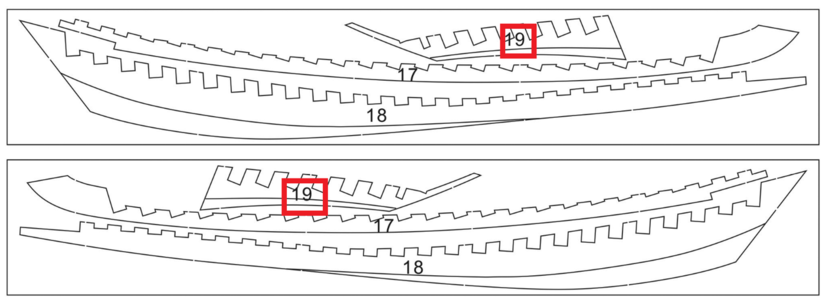
Our inventory shows Parts #19 marked in red.
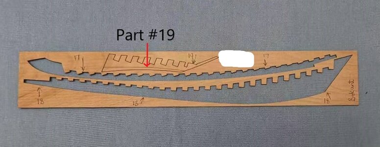
In reality, that is what Part #19 looks like. Those of you who have already installed Parts #17 and #18, will only have Part #19 left in this particular sheet.

Back to our inventory list, we see Parts #65 marked in red again.
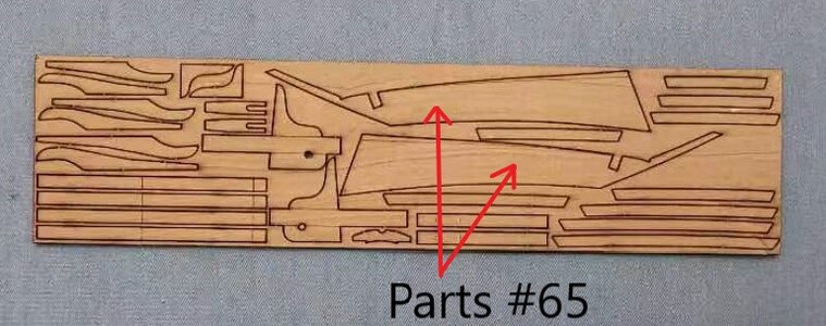
And in reality.
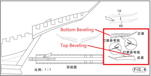
The assembly drawing indicates the positioning of these four parts on the keel as well as the fact that beveling is once again involved.
Now that we have identified the four role players in this part of the assembly, we can remove them from their sheeting. It is IMPORTANT TO NOTE THAT PARTS #19 and #65 ARE GLUED TOGETHER BACK TO BACK - so ultimately, we will only end up with two components that need to be attached to the keel.
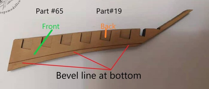
This view shows Part #65 at the back and Part #19 at the Front. NOTE : The Bevel line is at the bottom and faces to the outside.
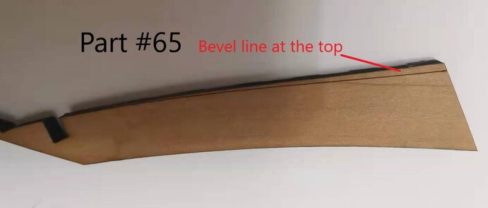
This picture shows the Reverse side of the previous picture. From this side, only Part #65 is visible - the bevel line is at the top and faces to the outside. CAUTION: Please make sure that you glue the correct pieces to one another!
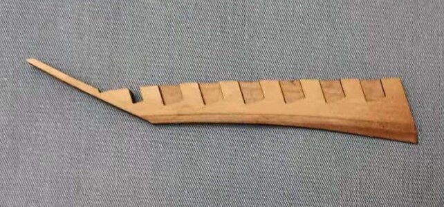
After the glue had dried I quickly beveled one side while there was enough sunshine. Beveling is not something I do in artificial light.
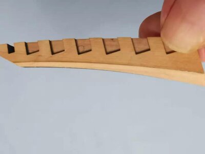
With both Parts #19 and #65 visible you can clearly see the beveling at the bottom.
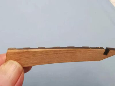
With only Part #65 visible the you can see the bevel at the top.
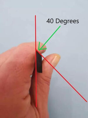
In my case, the bottom beveling measure exactly 40 Degrees.
That is all for now - more will follow tomorrow!
@marter1229 Terry asked me about the two parts that need to be added to the keel as part of the Transom and specifically with what the beveling should look like. I promised to give him an answer so I want to share it with all of you as part of the build procedure. For this assembly we will need four parts: 2 x Parts #19 and 2 x Parts #65.

Our inventory shows Parts #19 marked in red.

In reality, that is what Part #19 looks like. Those of you who have already installed Parts #17 and #18, will only have Part #19 left in this particular sheet.

Back to our inventory list, we see Parts #65 marked in red again.

And in reality.

The assembly drawing indicates the positioning of these four parts on the keel as well as the fact that beveling is once again involved.
Now that we have identified the four role players in this part of the assembly, we can remove them from their sheeting. It is IMPORTANT TO NOTE THAT PARTS #19 and #65 ARE GLUED TOGETHER BACK TO BACK - so ultimately, we will only end up with two components that need to be attached to the keel.

This view shows Part #65 at the back and Part #19 at the Front. NOTE : The Bevel line is at the bottom and faces to the outside.

This picture shows the Reverse side of the previous picture. From this side, only Part #65 is visible - the bevel line is at the top and faces to the outside. CAUTION: Please make sure that you glue the correct pieces to one another!

After the glue had dried I quickly beveled one side while there was enough sunshine. Beveling is not something I do in artificial light.

With both Parts #19 and #65 visible you can clearly see the beveling at the bottom.

With only Part #65 visible the you can see the bevel at the top.

In my case, the bottom beveling measure exactly 40 Degrees.
That is all for now - more will follow tomorrow!
Great stuff Heinrich!! I was looking at these pieces yesterday wondering what the proper procedure might be. Mounting these parts on to the keel seems a little different to me so I'll be happy to sit back and watch your take on it. Back to the frames for me!! 
@Heinrich :Hello Everyone
@marter1229 Terry asked me about the two parts that need to be added to the keel as part of the Transom and specifically with what the beveling should look like. I promised to give him an answer so I want to share it with all of you as part of the build procedure. For this assembly we will need four parts: 2 x Parts #19 and 2 x Parts #65.
View attachment 202261
Our inventory shows Parts #19 marked in red.
View attachment 202262
In reality, that is what Part #19 looks like. Those of you who have already installed Parts #17 and #18, will only have Part #19 left in this particular sheet.
View attachment 202263
Back to our inventory list, we see Parts #65 marked in red again.
View attachment 202264
And in reality.
View attachment 202268
The assembly drawing indicates the positioning of these four parts on the keel as well as the fact that beveling is once again involved.
Now that we have identified the four role players in this part of the assembly, we can remove them from their sheeting. It is IMPORTANT TO NOTE THAT PARTS #19 and #65 ARE GLUED TOGETHER BACK TO BACK - so ultimately, we will only end up with two components that need to be attached to the keel.
View attachment 202270
This view shows Part #65 at the back and Part #19 at the Front. NOTE : The Bevel line is at the bottom and faces to the outside.
View attachment 202271
This picture shows the Reverse side of the previous picture. From this side, only Part #65 is visible - the bevel line is at the top and faces to the outside. CAUTION: Please make sure that you glue the correct pieces to one another!
View attachment 202273
After the glue had dried I quickly beveled one side while there was enough sunshine. Beveling is not something I do in artificial light.
View attachment 202274
With both Parts #19 and #65 visible you can clearly see the beveling at the bottom.
View attachment 202275
With only Part #65 visible the you can see the bevel at the top.
View attachment 202276
In my case, the bottom beveling measure exactly 40 Degrees.
That is all for now - more will follow tomorrow!
This is Word-Perfect and Picture-Perfect.
Not that I still use that (first) program ...........
Regards, Peter
- Joined
- Jan 9, 2020
- Messages
- 10,378
- Points
- 938

@DonRobinson
@Peter Voogt
Thank you gents - that was quite fun to do and a nice break from the frames. But to me it's also back to frames - except for a small change I have made to the keel which I will inform you about tomorrow.
Kind regards - Heinrich
@Peter Voogt
Thank you gents - that was quite fun to do and a nice break from the frames. But to me it's also back to frames - except for a small change I have made to the keel which I will inform you about tomorrow.
Kind regards - Heinrich
- Joined
- Jan 9, 2020
- Messages
- 10,378
- Points
- 938

Hello Everyone
I want to share my "modification" that I mentioned last night. As you will recall, I explained how Parts #19 and #65 are combined (by gluing together) and then beveled.
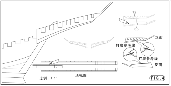
Here you can see how the #19/65 combination is glued to the keel - one on either side. For this, YuanQing has provided us with with a 1:1-scale drawing. This allows you to place the keel exactly over the drawing and then align the combined Part #19/65 in its correct - position. No problem here!
But now let's take a look at the picture below.
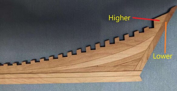
On my keel assembly - and I have no idea if this is peculiar to the way that I built the keel - the unbeveled part of Part #18 does not lie level with the sternpost - it is slightly higher (it is the same on the other side). This means that my combination Part #19/65 will not lie flush with the unbeveled section of Part #18 and the sternpost. My solution was as follows:
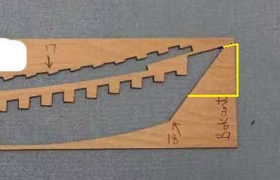
I simply cut out the piece (as is indicated in yellow) on the backing sheet which housed Part #18 making sure that I followed the exact lines of Part #18.
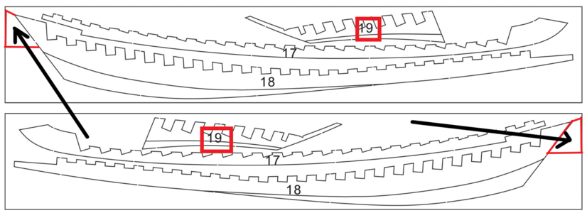
It is better illustrated on this drawing where the two sections that I cut out are marked in red and pointed out by the bold, black arrow. These I then glued onto the sternpost and once the glue had dried I cut off the overhang at the back.
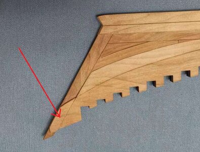
The inserted piece on the Port Side.
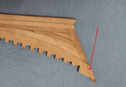
And on the starboard side.
Now everything is flush and ready to accommodate our combination part #19/65. As mentioned before, I don't know if you will be affected by the same issue, but if you are, you know what you can do.
Kind regards - Heinrich
I want to share my "modification" that I mentioned last night. As you will recall, I explained how Parts #19 and #65 are combined (by gluing together) and then beveled.

Here you can see how the #19/65 combination is glued to the keel - one on either side. For this, YuanQing has provided us with with a 1:1-scale drawing. This allows you to place the keel exactly over the drawing and then align the combined Part #19/65 in its correct - position. No problem here!
But now let's take a look at the picture below.

On my keel assembly - and I have no idea if this is peculiar to the way that I built the keel - the unbeveled part of Part #18 does not lie level with the sternpost - it is slightly higher (it is the same on the other side). This means that my combination Part #19/65 will not lie flush with the unbeveled section of Part #18 and the sternpost. My solution was as follows:

I simply cut out the piece (as is indicated in yellow) on the backing sheet which housed Part #18 making sure that I followed the exact lines of Part #18.

It is better illustrated on this drawing where the two sections that I cut out are marked in red and pointed out by the bold, black arrow. These I then glued onto the sternpost and once the glue had dried I cut off the overhang at the back.

The inserted piece on the Port Side.

And on the starboard side.
Now everything is flush and ready to accommodate our combination part #19/65. As mentioned before, I don't know if you will be affected by the same issue, but if you are, you know what you can do.
Kind regards - Heinrich


