You are using an out of date browser. It may not display this or other websites correctly.
You should upgrade or use an alternative browser.
You should upgrade or use an alternative browser.
Matthew 1497 1:48 scale by Mike 41 [COMPLETED BUILD]
- Thread starter Mike41
- Start date
- Watchers 27
-
- Tags
- completed build matthew
- Joined
- Aug 10, 2017
- Messages
- 1,646
- Points
- 538

Pumps
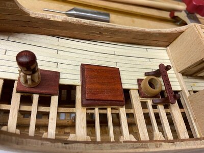
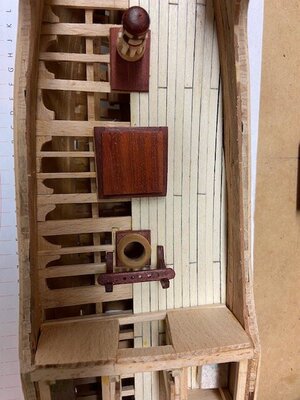
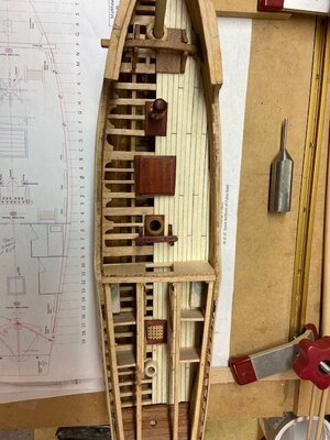
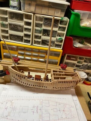
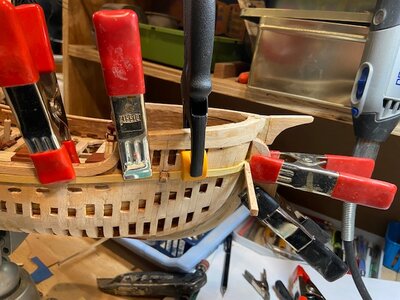
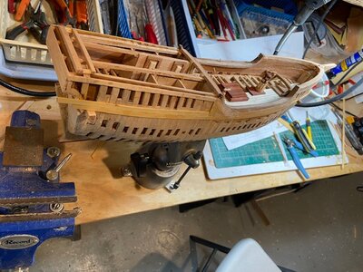
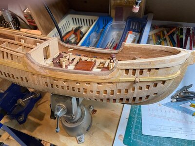
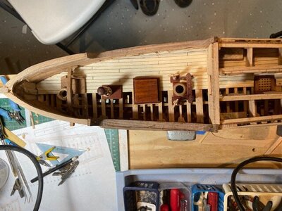
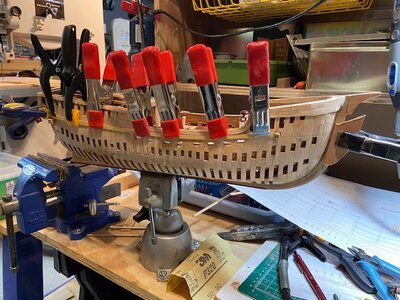
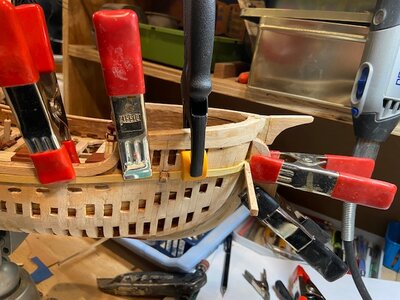
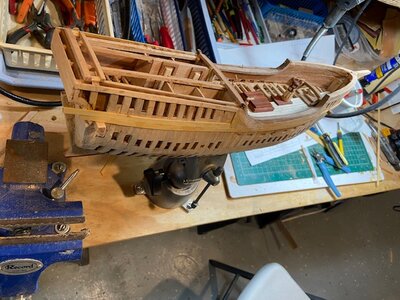
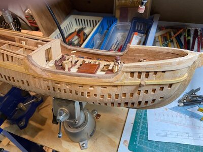
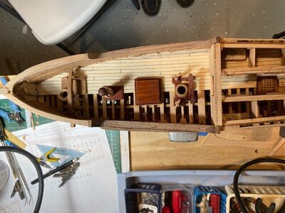
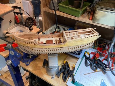
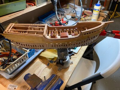
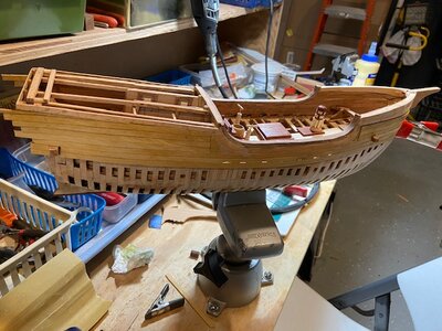
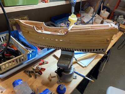
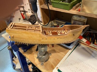
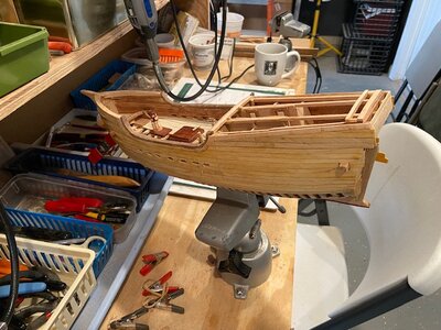
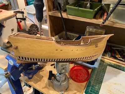
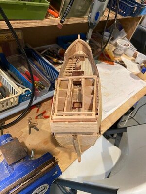
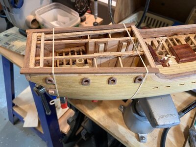
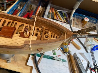
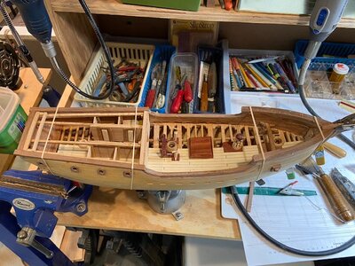
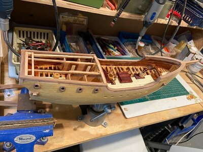
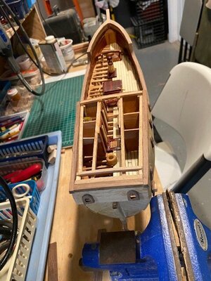
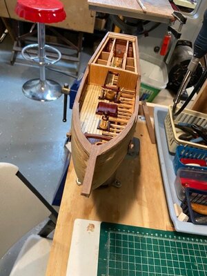
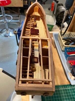
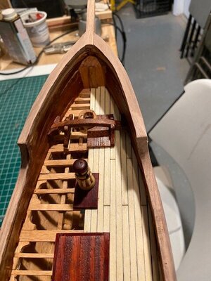
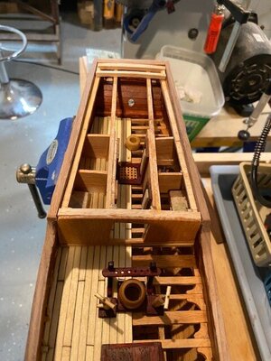
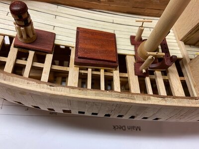
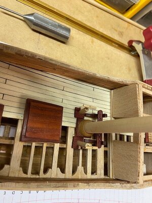
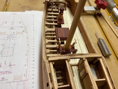
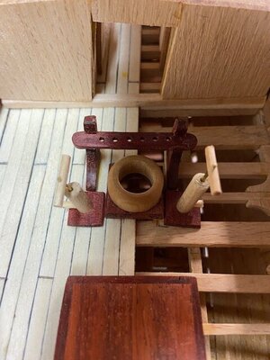
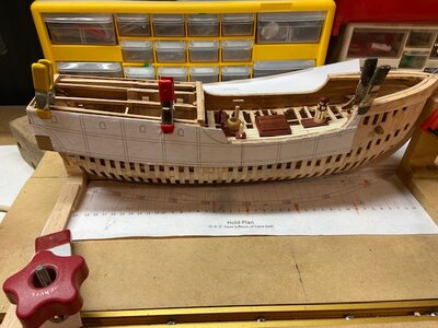
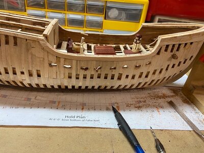
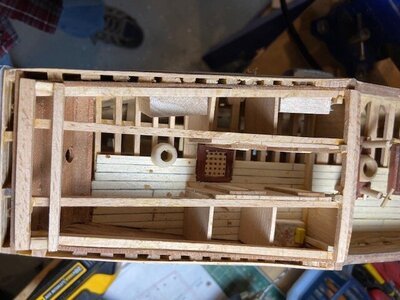
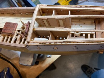
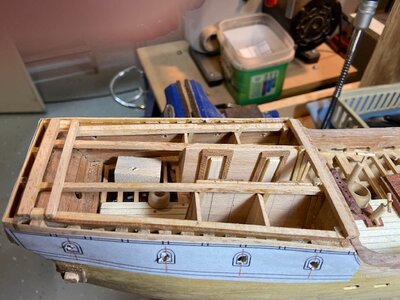
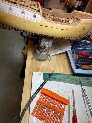
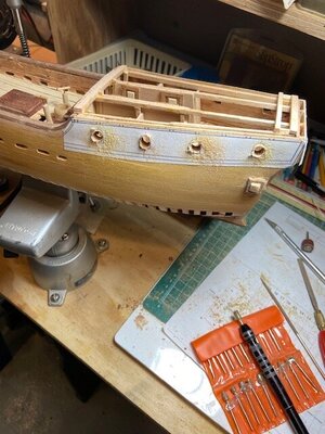
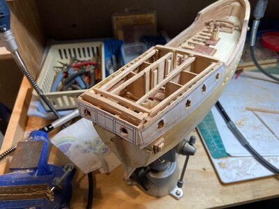
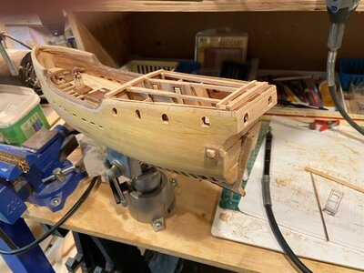
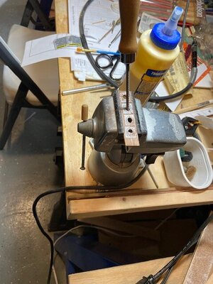
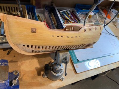
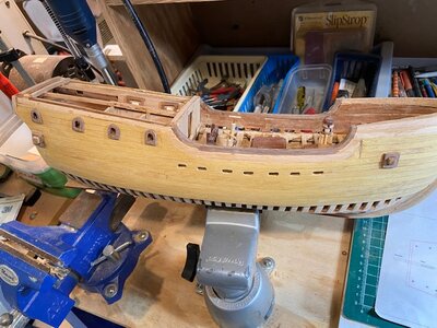
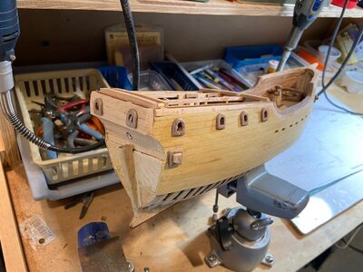
The pumps were easy to make and install, but when I started taking photos, I noticed I had forgotten the holes in the hull at deck level for water runoff. It would have been a lot easier drill the holes from the inside of the hull before I put all that stuff down the center of the ship. I used an 1/8” drill bit to start the slots and finished them with a small router bid in a Dremel tool. I have the starboard side roughed out and will finish both sides tomorrow.
Progress photos


- Joined
- Dec 1, 2016
- Messages
- 5,131
- Points
- 728

this last week Ev and i have been celebrating 44 years together so i did not do anything in the shop. Ok i did squeeze in a little bit of drawing on the Alva B which i will post. Each year we would pick a city and tour all the museums, parks and the city itself. This year was Cleveland our home town, boy things changed in 44 years.
But now i picked up the laser sheets for the decks and it is back to work.
Mike has been doing a fantastic job on the Matthew down to the details of everything. My part in this was to convert Mikes drawings into laser cutting files for anyone interested in building a framed up model of the Matthew.
the two sheets have all the deck beams, mast partners and knees. There will be a little fitting of parts.
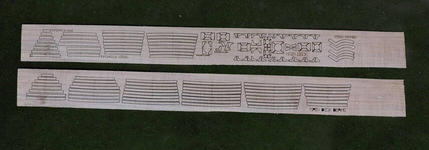
Question is how do you know what parts goes where? Well the answer is the laser sheets are laid out like the deck. i colored coded the parts so you can see what i am talking about.
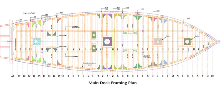
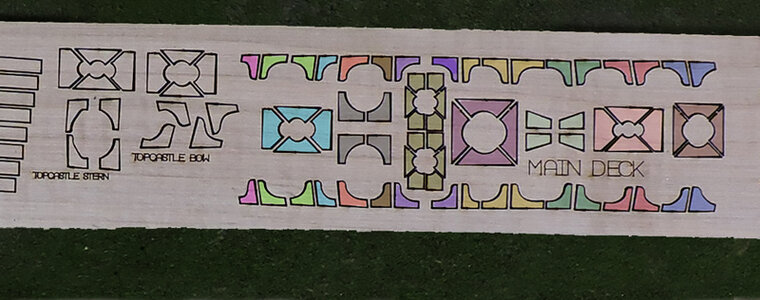
Before i begin building the decks first i have to sand the inside of the frames and set in the deck clamp.
But now i picked up the laser sheets for the decks and it is back to work.
Mike has been doing a fantastic job on the Matthew down to the details of everything. My part in this was to convert Mikes drawings into laser cutting files for anyone interested in building a framed up model of the Matthew.
the two sheets have all the deck beams, mast partners and knees. There will be a little fitting of parts.

Question is how do you know what parts goes where? Well the answer is the laser sheets are laid out like the deck. i colored coded the parts so you can see what i am talking about.


Before i begin building the decks first i have to sand the inside of the frames and set in the deck clamp.
Kurt Konrath
Kurt Konrath
I like the smaller cross sections builds, and I can wait to see this when finished and see what the kit cost will be when David is done tweaking all of Mikes work.
I TOO LIKE THE X SECTIONS, BUT THIS ONE AS IT IS, IT IS FOR ME FULL BUILD NOT MANY IF ANY POF FROM THIS ERA GREAT WORK MIKE AND DAVE. GOD BLESS STAY SAFE ALL DON
- Joined
- Dec 1, 2016
- Messages
- 5,131
- Points
- 728

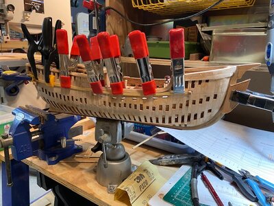
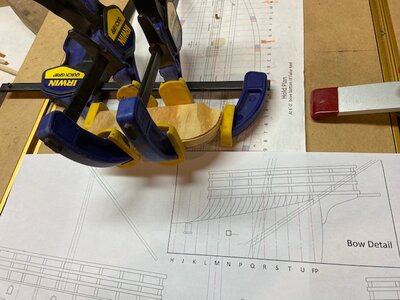
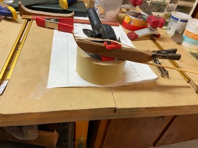
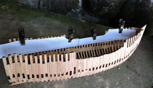
first thing to do in order to build the deck is locate where the deck clamp goes. I did this by making a pattern from the inside profile drawing and clamping it to the inside of the hull. The line above the edge is the actual deck then the space between the black line and the bottom edge of the pattern is the height of the deck beams. Finally the bottom edge of the pattern is the top of the deck clamp. Now it is just a matter of drawing a line on the inside of the hull.

Good idea to make it in your way with the papre pattern - Thanks for showing usfirst thing to do in order to build the deck is locate where the deck clamp goes. I did this by making a pattern from the inside profile drawing and clamping it to the inside of the hull. The line above the edge is the actual deck then the space between the black line and the bottom edge of the pattern is the height of the deck beams. Finally the bottom edge of the pattern is the top of the deck clamp. Now it is just a matter of drawing a line on the inside of the hull.
View attachment 329179
- Joined
- Dec 1, 2016
- Messages
- 5,131
- Points
- 728

the deck clamps are in and now i have to assemble the mast partners which are the items in blue
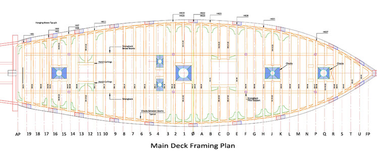
it is not a simple task of gluing the 4 sides together. looking at the setup notice the center is not round. This is because of the laser cutting process. If the laser cut on the drawing lines the parts would end up to small caused by the .012 kurf of the laser beam. So the cuts are offset to compensate for the loss from the beam, making the parts slightly to big, big is better than to small. It is not an issue just a slight sanding of the edges until the center circle is round and done.
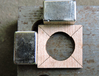

it is not a simple task of gluing the 4 sides together. looking at the setup notice the center is not round. This is because of the laser cutting process. If the laser cut on the drawing lines the parts would end up to small caused by the .012 kurf of the laser beam. So the cuts are offset to compensate for the loss from the beam, making the parts slightly to big, big is better than to small. It is not an issue just a slight sanding of the edges until the center circle is round and done.

- Joined
- Dec 1, 2016
- Messages
- 5,131
- Points
- 728

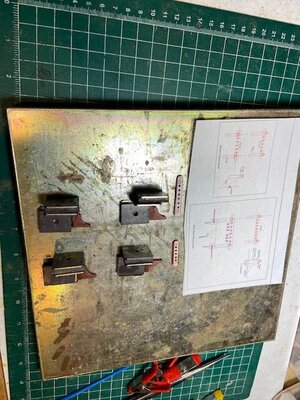
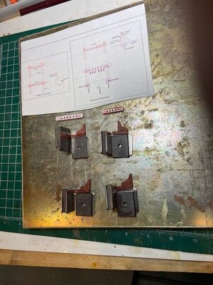
the way i assembled the mast partners is once again usung magnets and setting up a 90 degree corner. Once the magnets are in place they are difficult to move out of place.
as punched out of the laser sheet the fit is like this, my thumb gives a sense of scale.
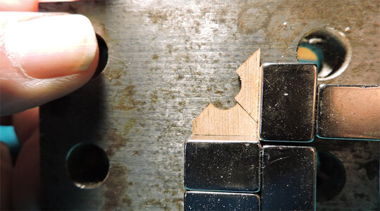
Sanding the corners a little at a time until the edges of the circle line up, then glue the two pieces together. After the first two pieces i will do the same with the other two, when they line up i will join both halves by the same process of a little sanding until everything lines up.
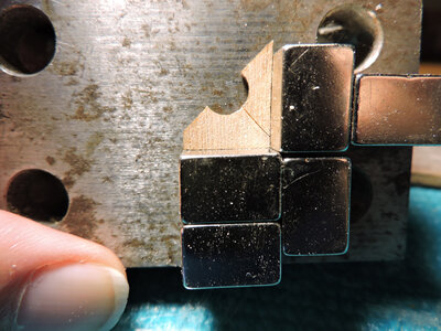
i have six of these to assemble when done i can start building the deck.
as punched out of the laser sheet the fit is like this, my thumb gives a sense of scale.

Sanding the corners a little at a time until the edges of the circle line up, then glue the two pieces together. After the first two pieces i will do the same with the other two, when they line up i will join both halves by the same process of a little sanding until everything lines up.

i have six of these to assemble when done i can start building the deck.
- Joined
- Dec 1, 2016
- Messages
- 5,131
- Points
- 728

sometimes you just have to abandon what your doing and find a different way. Building the mast partners in pieces just did not work out. To start with they are very small pieces that have to be sanded to fit together. i ended up rounding out the edges, and not getting a proper fit because the joining edges were no longer flat from trying to sand them. you can see the slight curve on the left side of the piece.
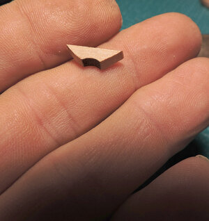
The solution and to avoid fustration i made copies of the parts from the drawings and glued them on sheet stock
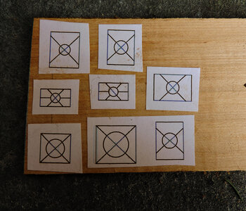
then drilled the center hole and cut out the parts, done in 20 minutes plus a little clean up.
to me it was a small detail that did not warrant the time and effort so one piece parts are fine for me.
With that out of the way i can start building the deck
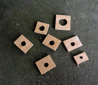

The solution and to avoid fustration i made copies of the parts from the drawings and glued them on sheet stock

then drilled the center hole and cut out the parts, done in 20 minutes plus a little clean up.
to me it was a small detail that did not warrant the time and effort so one piece parts are fine for me.
With that out of the way i can start building the deck

BEAUTIFULL WORK MIKE AS ALWAYS. GOD BLESS STAY SAFE YOU AND YOURS DON
- Joined
- Aug 10, 2017
- Messages
- 1,646
- Points
- 538

- Joined
- Aug 10, 2017
- Messages
- 1,646
- Points
- 538

Stern Windows
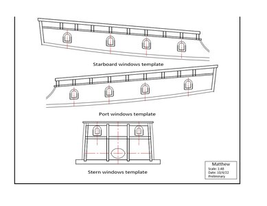
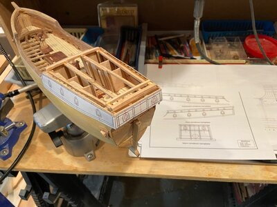
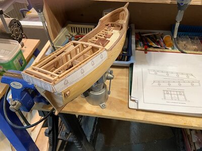
The windows are installed, the only problem I had was the guy that made the drawing made the frame too thin, he is going to get a pay cut. Lol I took a series of photos showing the sequence of the installation.
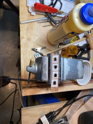
Attaching the patterns to the hull with spray adhesive and using some scrap balsa blocks on the interior to prevent out drilled the initial holes for the windows. Next, I enlarged the openings with a burr in the Dremel and a square and flat file to finish the openings. The frames are made the same way, drill a small hole and file it to shape I used walnut it is easy to work with hand tools and looks great against the yellowheart. The outside of the frames was shaped with a belt sander.
Progress photos.


WOW MIKE WHAT A BEAUTIFUL BUILD THIS ONE IS JUST SUPERB CRAFTMANSHIP AND QUICK ALSO JUS MARVOLOUSW. GOD BLESS STAY SAFE YOU AND YOURS DON
- Joined
- Aug 10, 2017
- Messages
- 1,646
- Points
- 538

Thanks Don, the frames for the Matthew are a lot simpler than the Minerva and it looks like you are making good progress with the new type of jig. After you have the frames built and in place on the keel this is a standard build.

