It is a small step for a man but a giant leap for your 2 decker. love it, the laminated scheerstrook lookes perfect. When you see it in the mould I would expect there is a severe knick, but not when shown on the model.
You are using an out of date browser. It may not display this or other websites correctly.
You should upgrade or use an alternative browser.
You should upgrade or use an alternative browser.
Hohenzollernmodell 1660-1670 Scale 1/75 POF build by Stephan Kertész (Steef66)
- Thread starter Steef66
- Start date
- Watchers 46
-
- Tags
- 1:75 dutch two-decker pof
- Joined
- Aug 8, 2019
- Messages
- 4,139
- Points
- 688

Thanks Maarten. When you bent the wood on the flat side you have to over done this a little bit. It always bent little back in straight form. That's the explanation of the knick in the mould.It is a small step for a man but a giant leap for your 2 decker. love it, the laminated scheerstrook lookes perfect. When you see it in the mould I would expect there is a severe knick, but not when shown on the model.
Hi Stephan,Thanks Maarten. When you bent the wood on the flat side you have to over done this a little bit. It always bent little back in straight form. That's the explanation of the knick in the mould.
Did you place the scheerstrook above the main wales instead of between? On the mid frame it seems to be just above the main width of the frame.
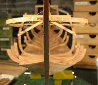
- Joined
- Aug 8, 2019
- Messages
- 4,139
- Points
- 688

It goes along the ceiling of the orlop deck. Starting at the transom just like the discription of Kamer. The master ribbons don't have to be along the wale or widest part of the ship.Hi Stephan,
Did you place the scheerstrook above the main wales instead of between? On the mid frame it seems to be just above the main width of the frame.
View attachment 392230
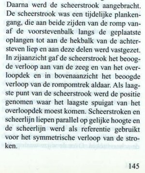
Last edited:
Haha as allways sources who are in contradiction with each other. I have read in multiple sources is was situated between the two main wales and removed when the main wales were fitted. Guess either both will work and give the same result.It goes along the ceiling of the orlop deck. Starting at the transom just like the discription of Kamer. The master ribbons don't have to be along the wale or widest part of the ship.
View attachment 392231
- Joined
- Aug 8, 2019
- Messages
- 4,139
- Points
- 688

Page 71 Cornelis van YkHaha as allways sources who are in contradiction with each other. I have read in multiple sources is was situated between the two main wales and removed when the main wales were fitted. Guess either both will work and give the same result.
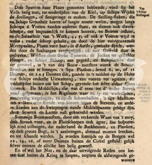
And I couldn't find it back so fast was that it follows the sheer of the ship. It passes the "onderste uitwatering" which is on the ceiling of the orlop or the floor the deck above the orlop. Don't know the name. And this deck starts on the transom. Wich source do you use?
Mainly Ab s Witsen book. I also have Van Eijk but read it many years ago. I will look it up and let you know.Page 71 Cornelis van Yk
View attachment 392268
And I couldn't find it back so fast was that it follows the sheer of the ship. It passes the "onderste uitwatering" which is on the ceiling of the orlop or the floor the deck above the orlop. Don't know the name. And this deck starts on the transom. Wich source do you use?
Actually in the fluyt there is a koebrug at the height where the lower wales are fitted. Using this position for the scheerstrook wil help me to fit the lower futtocks which are not reaching to the higher deck. The area where lower and higher futtocks meet is situated at the lower wales on the outside and koebrug on the inside creating a very sturdy construction. Fitting my scheerstrook higher will not support my lower futtocks.
Last edited:
- Joined
- Aug 8, 2019
- Messages
- 4,139
- Points
- 688

Either Kamer is wrong about that point, and got frozen in the idea he thinks about how it was done. Or the Hohenzollern model is totaly wrong build. The last thing I doubt, because looking to paintings I see more ships with a low belly.
But maybe I find the passage in Yk where he says that the scheerstrook is on the widest part. And in that case the HZ model is build wrong
Last edited:
- Joined
- Aug 8, 2019
- Messages
- 4,139
- Points
- 688

@Maarten I found the answer as to why the scheerstrook does not run across the widest part as Witse claimed. N. Kamer refutes that contention using perspective drawings. This is also described that way in his book. Van Yk makes no mention of this either and I myself had already seen from van de Velde's paintings and drawings that this proposition does indeed have snags. You mentioned it and I wanted to know if the HZ model is wrongly build.
This is what Kamer wrote about the scheerstrook:
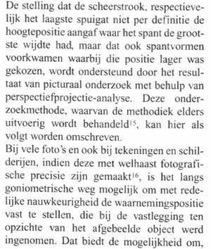
Translation:
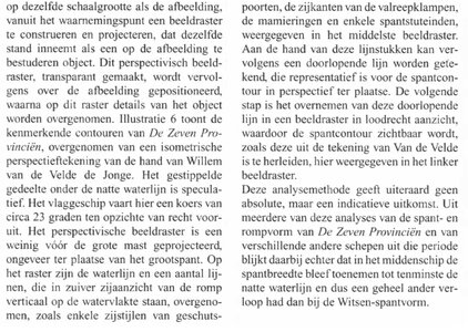
The contention that the scheerstrook and lowest scupper, respectively, did not necessarily indicate the height position where the frame had the greatest width, but that also frame forms occurred where that position was chosen lower, is supported by the result of pictorial research using perspective projection analysis. *** In many photographs and also in drawings and paintings, if they are made with almost photographic precision, it is possible by trigonometric means to determine with reasonable accuracy the observation position, which was occupied at the time of capture in relation to the depicted object. This offers the possibility of constructing and projecting from the observation point, at the same scale as the image, an image grid, which occupies the same as an object to be studied on the image. This perspective image grid, made transparent, is then positioned over the image, after which details of the object are copied onto this grid. Illustration 6 shows the characteristic contours of de Zeven Provinciën, taken from an isometric perspective drawing by Willem van de Velde the Younger. The dotted area below the waterline is speculative. The flagship is here sailing a course of about 23 degrees relative to straight ahead. The perspective image grid is projected a little in front of the main mast, approximately at the location of the main truss. On the grid, the waterline and some lines, which in pure side view of the hull are vertical to the water plane, such as some side uprights of gun ports, the sides of the halyard lights, the mamier rings and some frames of the truss struts, are reproduced in the center image grid. These line segments can then be used to draw a continuous line representative of the frame contour in perspective on site. The next step is to copy this continuous line into an image grid in perpendicular view, revealing the frame contour as derived from Van de Velde's drawing, shown here in the left image grid. Of course, this method of analysis does not give absolute, but indicative results. However, several of these analyses of the frame and hull form of De zeven Provinciën and of several other ships of the period show in the process that in the midship the truss width continued to increase to at least the wet water line and thus had a completely different course than in the Witse frame form
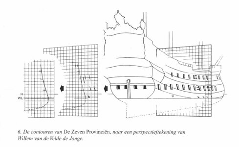
So, in the drawing above, the scheerstrook should run just above the lower gun ports as it follows the ship's sheer. And the wales don't follow the scheerstrook either.
The ship Witse built had the lowest scuppers at the widest part of the ship. As a result, the proposition that the scheerstrook ran across the widest part has crept in to many. But so this was not always the case. And so it does not have to follow the widest part.
Why there is a scheerstrook?
The scheerstrook is much stronger then the centlatten. The centlatten can't suppert the Oplangen andother parts of the frames, they just to weak. That is the reason for such a heavy temporary scheerstrook. The scheerstrook isn't throw away after the use, but they use it again on another build.
Another fact is also if you study this whole matter, that the wales are not flush with the scheerstrook. Often this is the case, but it does not have to be and therefore are not related. You also often see that the gun ports are often in the wale, especially in the stern area. This is because the gunwales are not flush with the sheer.
This is what Kamer wrote about the scheerstrook:


Translation:
The contention that the scheerstrook and lowest scupper, respectively, did not necessarily indicate the height position where the frame had the greatest width, but that also frame forms occurred where that position was chosen lower, is supported by the result of pictorial research using perspective projection analysis. *** In many photographs and also in drawings and paintings, if they are made with almost photographic precision, it is possible by trigonometric means to determine with reasonable accuracy the observation position, which was occupied at the time of capture in relation to the depicted object. This offers the possibility of constructing and projecting from the observation point, at the same scale as the image, an image grid, which occupies the same as an object to be studied on the image. This perspective image grid, made transparent, is then positioned over the image, after which details of the object are copied onto this grid. Illustration 6 shows the characteristic contours of de Zeven Provinciën, taken from an isometric perspective drawing by Willem van de Velde the Younger. The dotted area below the waterline is speculative. The flagship is here sailing a course of about 23 degrees relative to straight ahead. The perspective image grid is projected a little in front of the main mast, approximately at the location of the main truss. On the grid, the waterline and some lines, which in pure side view of the hull are vertical to the water plane, such as some side uprights of gun ports, the sides of the halyard lights, the mamier rings and some frames of the truss struts, are reproduced in the center image grid. These line segments can then be used to draw a continuous line representative of the frame contour in perspective on site. The next step is to copy this continuous line into an image grid in perpendicular view, revealing the frame contour as derived from Van de Velde's drawing, shown here in the left image grid. Of course, this method of analysis does not give absolute, but indicative results. However, several of these analyses of the frame and hull form of De zeven Provinciën and of several other ships of the period show in the process that in the midship the truss width continued to increase to at least the wet water line and thus had a completely different course than in the Witse frame form

So, in the drawing above, the scheerstrook should run just above the lower gun ports as it follows the ship's sheer. And the wales don't follow the scheerstrook either.
The ship Witse built had the lowest scuppers at the widest part of the ship. As a result, the proposition that the scheerstrook ran across the widest part has crept in to many. But so this was not always the case. And so it does not have to follow the widest part.
Why there is a scheerstrook?
The scheerstrook is much stronger then the centlatten. The centlatten can't suppert the Oplangen andother parts of the frames, they just to weak. That is the reason for such a heavy temporary scheerstrook. The scheerstrook isn't throw away after the use, but they use it again on another build.
Another fact is also if you study this whole matter, that the wales are not flush with the scheerstrook. Often this is the case, but it does not have to be and therefore are not related. You also often see that the gun ports are often in the wale, especially in the stern area. This is because the gunwales are not flush with the sheer.
Last edited:
Wow so cool, I love this design more and more.
.
Hello Stephan in your thread,
If you wish, I can take a closer look at it. But I am already almost certain that Kamer is wrong on this one. The perspective images are extremely misleading and should be disregarded unless there is really no other option; I don't think he took into account the needs of a hydrostatic nature at all, especially stability, already perfectly realised at the time; and besides, I find it hard to imagine a more important function of the scheerstrook, both conceptually and structurally, than to determine the greatest breadth of the hull, so much needed for the correct alignment of the frame elements.
.
I could not be happier reading such posts, where members offered help in very complex subjects (at least for me complex for sure). Thank you!!.
Hello Stephan in your thread,
If you wish, I can take a closer look at it. But I am already almost certain that Kamer is wrong on this one. The perspective images are extremely misleading and should be disregarded unless there is really no other option; I don't think he took into account the needs of a hydrostatic nature at all, especially stability, already perfectly realised at the time; and besides, I find it hard to imagine a more important function of the scheerstrook, both conceptually and structurally, than to determine the greatest breadth of the hull, so much needed for the correct alignment of the frame elements.
.
Hi Stephan,
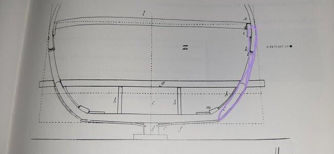
I agree with Waldemar here. Constructually it doesn t make sense not to have the scheerstrook with the sheer of the vessel. That the gun ports are not in line with the sheer is caused by the fact that the decks were laid more flat during the course of the 17th century to create a flat platform for the guns. You don t see this for instance on a fluyt which is used freight.
If the scheerstrook is used for building up the frames then the top of the first oplangen (futtock) should reach it.
Normally the first oplangen run from bilge to the koebrug deck. If the scheerstrook would be higher the first futtock won t reach the scheerstrook which would therefore be useless.
I don t think that you should take de laagste uitwatering to literary, I think the koebrug deck on my ship is the laagste uitwatering allthough there is no actual drain towards the outside of the hull.
See below the first futtock in purple.

- Joined
- Aug 8, 2019
- Messages
- 4,139
- Points
- 688

Thanks guys for your contribution. I didn't sleep last night and I even went up early to find out why I couldn't sleep. I made a mistake in the alignment. @Maarten mentioned in his comment that decks where flat out on these ships. I didn't think about that (forget this part, getting old) and mistaken the deck for shear of the ship. And positioned the lower drain on the ceiling  . I will explain later what went wrong. So I come back to it.
@- Waldemar - Thanks for your contribution and visit to my log. I think that you want to say that you do not agree with the idea of N. Kamer and not that he is wrong. To say that someone is wrong in their explanation precludes any discussion in further course of the conversation. I do not agree with all the fact that Kamer mentions in his book, I also question many comments he makes because some things are not fully explained. But I have that fact with more modern writers on the subject. Often they leave things too superficial or don't give a good answer to an issue. But that does not mean they are wrong.
I studied physics and mathematics, so I believe perspective projection analysis are a good instrument to use. I also have a gift for being able to perceive things in perspective, which makes me look at things differently. I have less trouble perceiving things in 3D from a flat drawing than someone else. I don't have to use this projection provision to see it. But it is nice that Kamer shows a method by which this can be demonstrated.
I will come back later with an explanation what went wrong and why, also what my opinion of the function of the scheerstrook. I believe there is another function then just to mark out the shape of the ship.
 . I will explain later what went wrong. So I come back to it.
@- Waldemar - Thanks for your contribution and visit to my log. I think that you want to say that you do not agree with the idea of N. Kamer and not that he is wrong. To say that someone is wrong in their explanation precludes any discussion in further course of the conversation. I do not agree with all the fact that Kamer mentions in his book, I also question many comments he makes because some things are not fully explained. But I have that fact with more modern writers on the subject. Often they leave things too superficial or don't give a good answer to an issue. But that does not mean they are wrong.
I studied physics and mathematics, so I believe perspective projection analysis are a good instrument to use. I also have a gift for being able to perceive things in perspective, which makes me look at things differently. I have less trouble perceiving things in 3D from a flat drawing than someone else. I don't have to use this projection provision to see it. But it is nice that Kamer shows a method by which this can be demonstrated.
I will come back later with an explanation what went wrong and why, also what my opinion of the function of the scheerstrook. I believe there is another function then just to mark out the shape of the ship.
Last edited:
.
I see. Please take my statement as an unfortunate mental shortcut for the sake of brevity. Apologies and good luck.
.
How unfortunate it is that none of us here can communicate in our mother tongue. That makes it difficult for me to understand what exactly is meant.
It is about the position of the scherstrook at its lowest point.
It is related to the scuppers.
It's about the Hohenzollern model.
The model specifies the heights.
What did I not understand?
Greetings bela
It is about the position of the scherstrook at its lowest point.
It is related to the scuppers.
It's about the Hohenzollern model.
The model specifies the heights.
What did I not understand?
Greetings bela
- Joined
- Sep 3, 2021
- Messages
- 4,250
- Points
- 688

Hear, hear!Dear Stephan, Maarten and Waldemar
You have such a brilliant discussion here that it should be encouraged at all costs. Please continue.
- Joined
- Aug 8, 2019
- Messages
- 4,139
- Points
- 688

This went wrong with the positioning of the Master Ribband (scheerstrook).
At the time I started with the scheerstrook, I knew only a few things about it and thought I could even demonstrate it in the drawings of the Dutch 2-decker. But after looking into it carefully I found out how it should be made. I actually got rid of it in a quick way that later turned out to be partially wrong. Not quite, because the line I made is on the ship it's just not the scheerstrook. I followed Van Eyck's method using the line plan I made in AutoCAD. Because of this I made a mistake by not looking carefully where the bottom position of the scuppers (wateruitloop) is. I kept the top of the orlop deck when it should have been the bottom.
As a result, the scheerstrook was not set at the correct height.
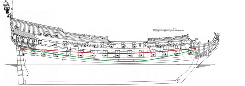
Red is mine and green as it should be. Where the point at the bow is debatable.
As I said, this line is also present on the ship and fortunately doesn't matter. So I will leave this one in that spot. And later add several strips to expand the shape of the ship. First calve the bottom (close it with floor timber).
Actually I am now following the advice @Ptèr gave me. On modelbouwforum.nl
Because honestly, determining the right place for the scheerstrook is quite a thing, something that on a model is quite a daunting piece of work. Since Witse gives a lot of dimensions for this, it is very difficult to draw this out on a model. I have the waterlines from Winter's drawings and will use them. Much easier to handle, and without making mistakes.
I will come back to the scheerstrook when I have studied and discussed the matter thoroughly. Because there are quite a few misconceptions going around.
@Bela Ich versuche, ihn für Sie und andere Sprachkollegen ins Deutsche zu übersetzen. Ich spreche einigermaßen gut Deutsch, also ein kleiner Versuch für mich, um zu sehen, ob die Übersetzung einigermaßen korrekt ist.
Das ging mit der Positionierung des Scherstraks schief.
Als ich mit dem Scherstrak anfing, wusste ich nur ein paar Dinge darüber und dachte, ich könnte es sogar in den Zeichnungen des holländischen 2-Deckers demonstrieren. Aber nachdem ich mich richtig damit beschäftigt hatte, fand ich heraus, wie er gemacht werden sollte. Ich bin ihn tatsächlich auf eine schnelle Art und Weise losgeworden, die sich später als teilweise falsch herausstellte. Nicht ganz, denn die Linie, die ich gemacht habe, ist auf dem Schiff, sie ist nur nicht der Scherstrak. Ich folgte der Methode von Van Eyck und verwendete den Linienplan, den ich in AutoCAD erstellt hatte. Dabei habe ich einen Fehler gemacht, weil ich nicht genau darauf geachtet habe, wo sich die Abflussrohre befinden. Ich habe die Oberseite des Oberlaufdecks beibehalten, obwohl es die Unterseite hätte sein sollen.
Infolgedessen wurde der Scherstrak nicht auf die richtige Höhe gesetzt.

Rot ist meins und grün, wie es sein sollte. Wo der Punkt am Bug ist, darüber lässt sich streiten.
Wie gesagt, diese Linie ist auch auf dem Schiff vorhanden und spielt zum Glück keine Rolle. Ich werde sie also an dieser Stelle belassen. Und später mehrere Streifen hinzufügen, um die Form des Schiffes zu erweitern. Zuerst wird der Boden gekalbt (mit Bauchstücken versiegelt).
Eigentlich befolge ich jetzt den Rat, den mir @Ptèr gegeben hat. Im Modelbouwforum.
Denn um ehrlich zu sein, ist die Bestimmung der richtigen Stelle für den Scherstrak eine Sache, die am Modell ein ziemliches Stück Arbeit ist. Da Witse dafür sehr viele Maße angibt, ist es sehr schwierig, das am Modell nachzuzeichnen. Ich habe die Wasserlinien aus Winters Zeichnungen und werde sie verwenden.
Ich werde auf den Scherstrak zurückkommen, wenn ich das Thema gründlich studiert und diskutiert habe. Es kursieren nämlich eine ganze Reihe von Missverständnissen.
At the time I started with the scheerstrook, I knew only a few things about it and thought I could even demonstrate it in the drawings of the Dutch 2-decker. But after looking into it carefully I found out how it should be made. I actually got rid of it in a quick way that later turned out to be partially wrong. Not quite, because the line I made is on the ship it's just not the scheerstrook. I followed Van Eyck's method using the line plan I made in AutoCAD. Because of this I made a mistake by not looking carefully where the bottom position of the scuppers (wateruitloop) is. I kept the top of the orlop deck when it should have been the bottom.
As a result, the scheerstrook was not set at the correct height.

Red is mine and green as it should be. Where the point at the bow is debatable.
As I said, this line is also present on the ship and fortunately doesn't matter. So I will leave this one in that spot. And later add several strips to expand the shape of the ship. First calve the bottom (close it with floor timber).
Actually I am now following the advice @Ptèr gave me. On modelbouwforum.nl
Because honestly, determining the right place for the scheerstrook is quite a thing, something that on a model is quite a daunting piece of work. Since Witse gives a lot of dimensions for this, it is very difficult to draw this out on a model. I have the waterlines from Winter's drawings and will use them. Much easier to handle, and without making mistakes.
I will come back to the scheerstrook when I have studied and discussed the matter thoroughly. Because there are quite a few misconceptions going around.
@Bela Ich versuche, ihn für Sie und andere Sprachkollegen ins Deutsche zu übersetzen. Ich spreche einigermaßen gut Deutsch, also ein kleiner Versuch für mich, um zu sehen, ob die Übersetzung einigermaßen korrekt ist.
Das ging mit der Positionierung des Scherstraks schief.
Als ich mit dem Scherstrak anfing, wusste ich nur ein paar Dinge darüber und dachte, ich könnte es sogar in den Zeichnungen des holländischen 2-Deckers demonstrieren. Aber nachdem ich mich richtig damit beschäftigt hatte, fand ich heraus, wie er gemacht werden sollte. Ich bin ihn tatsächlich auf eine schnelle Art und Weise losgeworden, die sich später als teilweise falsch herausstellte. Nicht ganz, denn die Linie, die ich gemacht habe, ist auf dem Schiff, sie ist nur nicht der Scherstrak. Ich folgte der Methode von Van Eyck und verwendete den Linienplan, den ich in AutoCAD erstellt hatte. Dabei habe ich einen Fehler gemacht, weil ich nicht genau darauf geachtet habe, wo sich die Abflussrohre befinden. Ich habe die Oberseite des Oberlaufdecks beibehalten, obwohl es die Unterseite hätte sein sollen.
Infolgedessen wurde der Scherstrak nicht auf die richtige Höhe gesetzt.

Rot ist meins und grün, wie es sein sollte. Wo der Punkt am Bug ist, darüber lässt sich streiten.
Wie gesagt, diese Linie ist auch auf dem Schiff vorhanden und spielt zum Glück keine Rolle. Ich werde sie also an dieser Stelle belassen. Und später mehrere Streifen hinzufügen, um die Form des Schiffes zu erweitern. Zuerst wird der Boden gekalbt (mit Bauchstücken versiegelt).
Eigentlich befolge ich jetzt den Rat, den mir @Ptèr gegeben hat. Im Modelbouwforum.
Denn um ehrlich zu sein, ist die Bestimmung der richtigen Stelle für den Scherstrak eine Sache, die am Modell ein ziemliches Stück Arbeit ist. Da Witse dafür sehr viele Maße angibt, ist es sehr schwierig, das am Modell nachzuzeichnen. Ich habe die Wasserlinien aus Winters Zeichnungen und werde sie verwenden.
Ich werde auf den Scherstrak zurückkommen, wenn ich das Thema gründlich studiert und diskutiert habe. Es kursieren nämlich eine ganze Reihe von Missverständnissen.
Last edited:


