- Joined
- Aug 10, 2017
- Messages
- 1,646
- Points
- 538

Ship History:
His Majesty Yacht (HMY) Fubbs was laid down at Greenwich shipyards by Phineas Pett in 1682 and broken up in 1781.
By Royal Navy standards yachts would be the size of a typical harbor dispatch vessel or lightly armed gunboat. HMY Fubbs sported a keel length of only 63’ with at a specified 148 tons fully loaded. With a 21’ breadth and only 9’6” depth in hold these small ships carried a crew of up to 30 and could be armed with 8 – 12 3 pounders.
The Model:
The design and prototype for the model was done by Mike Shanks for Weasel Works.
Frames:
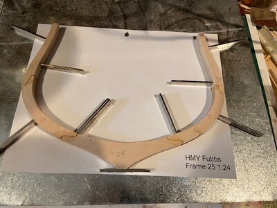
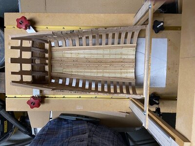
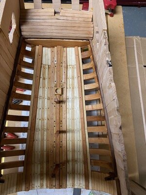
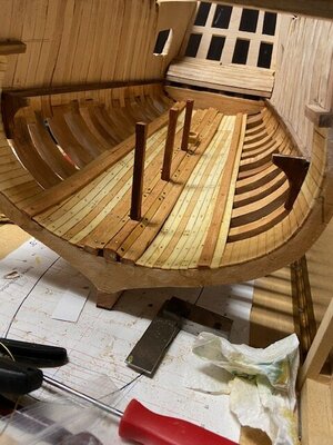
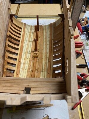
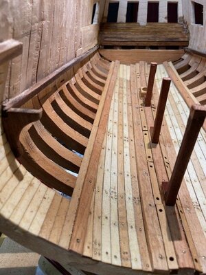
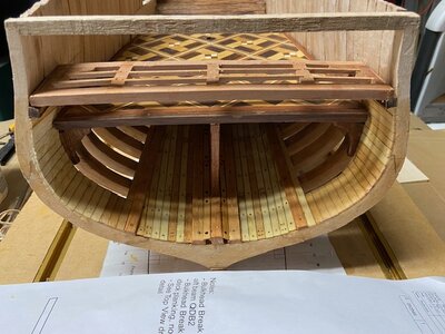
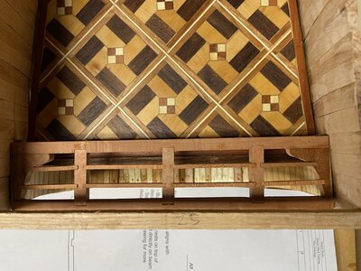
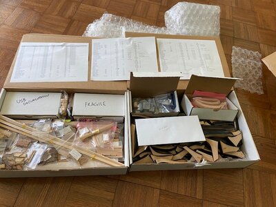
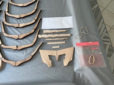
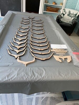
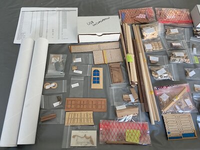
It has been a while since I built a kit and the first time, I used laser cut frames. The large scale 1:24 made the parts easy to handle the eight pieces are joined with lap joints Making them very easy to assemble, with the exception of frame #25 the forward frame. It was cut using a CNC machine and uses scarph joints that fit perfectly together.
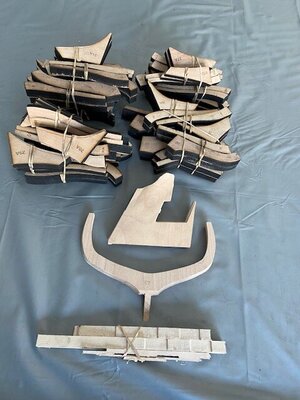
After removing the frames from the shipping box, I sorted the frames. Each part has the frame number etched on the aft side of the frame making the orientation easy to maintain. The bevel lines were also etched into the frame parts also. After sorting the parts I bundled them by frame number and divided them into five stacks. Divide & Conquer LOL.
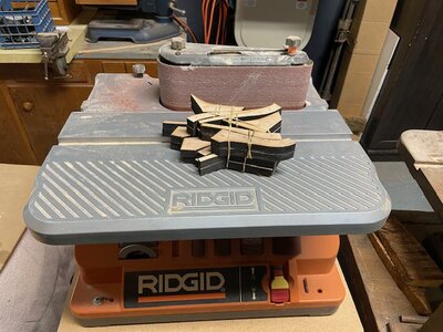
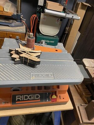
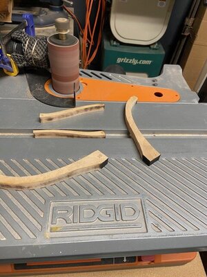
Removing the char was not too bad using a spindle sander, but using the port on the machine for the vacuum left a lot of dust in the air so I clamped the hose about a quarter inch off the spindle that removed almost all the dust.
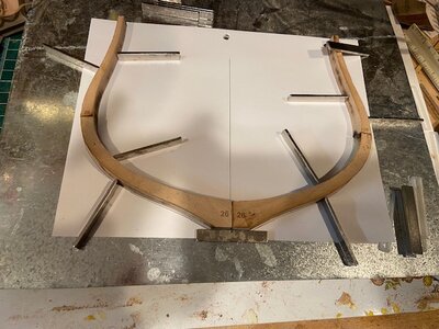
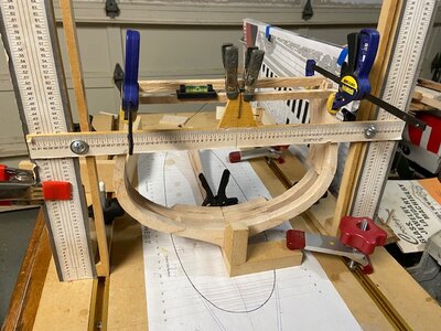
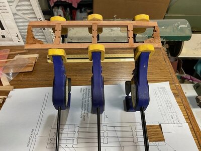
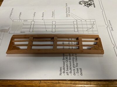
I assembled the frames by placing the frame drawing on a sheet metal plate and using magnets to hold the parts in place while the glue dried.
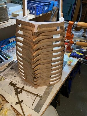
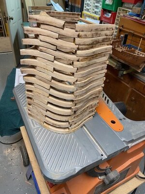
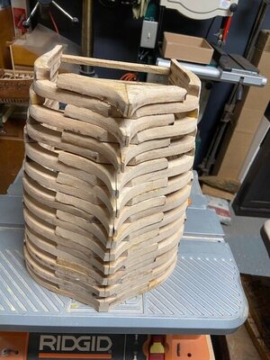
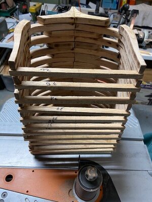
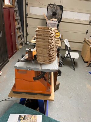
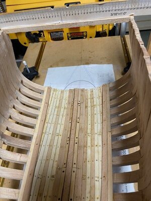
When the glue dried, I formed a vertical stack to check the bevels.
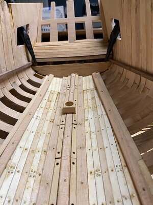
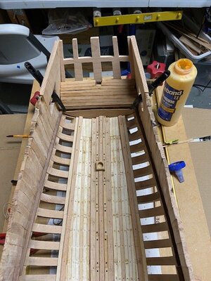
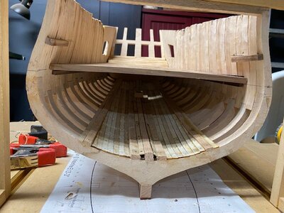
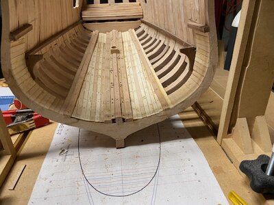
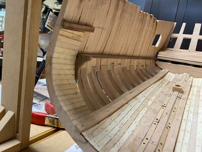
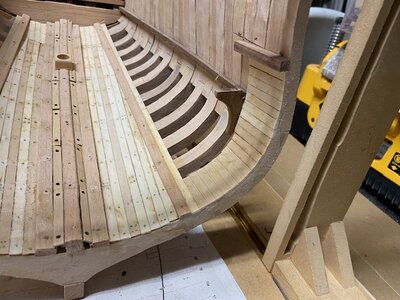
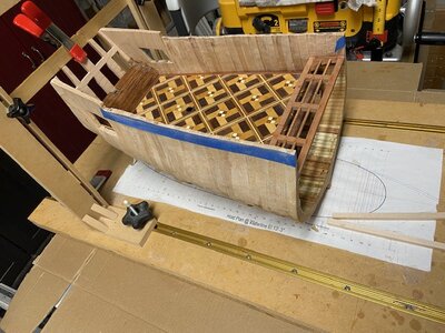
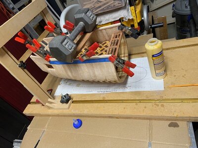
Progress photos:


Last edited:

