What capacity, what good work, what patience. I love it, a piece of learning for me. Thank you. Thanks for sharing.
You are using an out of date browser. It may not display this or other websites correctly.
You should upgrade or use an alternative browser.
You should upgrade or use an alternative browser.
HMS Royal William 1719, Euromodel, 1:72
- Thread starter KeithW
- Start date
- Watchers 18
-
- Tags
- euromodel royal william
- Joined
- Jun 13, 2022
- Messages
- 241
- Points
- 143

Fantastic level of detail … very inspiringMany years ago, my friend passed away. He was only 41 years old. I was actually working on this ship when I received a phone call to tell me the terrible news. I painted a tribute to Daniel on one of the bulkheads:
View attachment 400855
Over the years, the partially completed ship has been on display in my living room and I see that memorial every time I looked at the ship. I could not bear to cover it up forever, so I installed some magnets - those silver things on each corner of the hole. This way I can remove the grate and look at the memorial.
View attachment 400856
Once the grate is installed, you would never suspect that it could be removed to reveal a hidden message inside.
View attachment 400857
View attachment 400858
The quarterdeck railings were devilishly difficult to make. The railings alone contain 40 parts (not counting the stanchions, of which there are 34). Of those 40 parts, 12 hard to be carved because it is simply not possible to bend wood like that. You will notice that I included the Newell posts (the turned stanchions at the ends of the railings at the top of the staircase). These were turned from a toothpick on a Dremel. I used needle files to shape them.
The mast collar was made on my lathe. I don't know if Euromodel provided mast collars, I searched around in my parts and couldn't find any. So I made them.
You will also notice that the gratings have a subtle curve. The cannonball channel was made on my Proxxon mill and IT TOOK FOREVER. The first problem was figuring out how to hold the workpiece down. I made a custom jig out of some spare plywood by using the mill to draw a straight line, then I glued two pieces of wood using the straight line as a guide. Then I used the mill again to square up the faces to make sure they were 100% parallel. A couple of self tapping screws held the workpiece down while I milled out the holes for the cannonballs. In the end I managed to get an excellent result.
Hello Keith,
just catching up on your wonderful build log. You have certainly taken this kit to the next level with scratch building.
I gave up on my RW kit in despair half way through my build. The quality of the kit was disappointing compared to modern model ship kits.
Glad to see your excellent work my friend.
Great to see you here Keith and good to see your excellent progress on this challenging but rewarding kit.
- Joined
- Apr 11, 2015
- Messages
- 92
- Points
- 103

Thank you @Maarten, @Uwek, @Adry, @KeithLyall, @Bryian, and @NMBROOK for your comments. @Bryian if you recall, it was you who persuaded me to build this ship in the first place. I was going to do the Victory, but you said "everybody is doing the Victory". I do not regret making this model, even if I question my sanity sometimes when tackling the more difficult parts of this kit. I can honestly say that if it was not for online communities, I would not try to build this ship to the standard that it is, even though I feel it should have been built to an even higher standard. I am not limited by time (after all, it's not as if it's a commissioned piece for a client, it's for my own enjoyment!) or money (ship model making is a cheap hobby when compared to anything else!), I am limited by skills and knowledge. To prove my point about how inexpensive this hobby is, to get to this point it has taken me 9 years (minus 5 years of not working on it at all). The kit cost about AUD$2000, and all the various optional bits that I purchased maybe an extra $500. I spend more money on that on coffee alone every year.
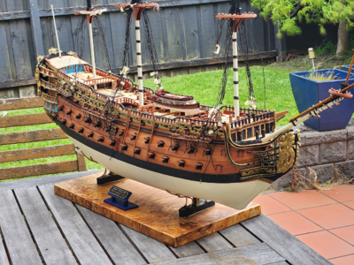
Anyway, as mentioned earlier, the build has stalled due to lack of sufficient rope for rigging. So I constructed a plinth to replace the stand provided by Euromodel:
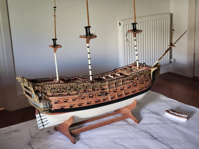
There is nothing wrong with the stand, it is sturdy, made of nice wood, and does the job. But ... I needed a way to route power into the model for the lights, and the Euromodel stand would leave wires dangling out in plain sight. So I constructed my own stand:
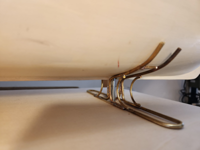
This is 3mm brass rod, bent on a vice and soldered. A thick stainless steel bolt goes through the middle and into a nut I installed in the false keel very early on in the build. The washer for the bolt has connections to the battery soldered on it. The whole assembly is pleasingly solid and holds the ship up no problem.
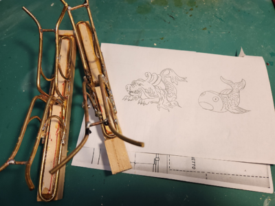
My initial idea was to sculpt a sea monster that is commonly illustrated in maps of the period out of Sculpey, thus hiding the stand and the steel bolt. I needed to make 4 of them. However, after making the first one, I mounted it on the base and found that it was far too large and it called too much attention to itself. It wouldn't be a stand for a model ship any more, instead it would be a stand with a model ship on top. So I scrapped the idea and went for a simpler stand.
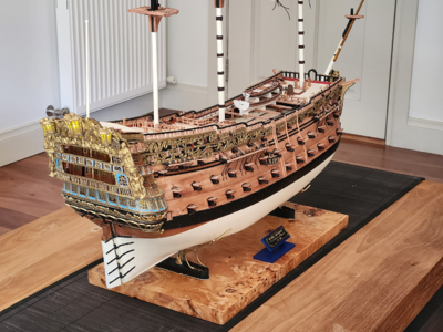
This is what I ended up with. I simply painted over the brass and constructed a plinth from plywood. I then covered the plinth in a burl veneer.
If you have never used a veneer before, let me tell you this is a completely different kettle of fish. I thought it would be pretty easy, after all planking is nothing more than applying veneer to a frame, right? Wrong! Step 1 is to find a suitable veneer. I was fortunate enough to find Australian Premium Veneers, not far from where I live. I made an appointment and visited them, and bought two sequential sheets of Mappa Burl for AUD$39 each. Step 2 is to flatten the veneer - the wild figurations of the veneer means that it is a warped mess when you receive it. Spray it with water, and sandwich it between two boards for 24 hours. Once it is flattened, it will start to curl up again if not used within the next few hours. I diluted some PVA with water (70% PVA, 30% water) and brushed it on. I then sandwiched it between the two boards again with some cling wrap in between, and waited another 24 hours. Then it was time for the sides, and you guessed it - 24 hours for each side waiting for it to dry. That's 6 days on the plinth already, just waiting for wood or glue to dry. Sandwiching glued up boards dramatically slows down the rate that glue cures.
Then it was time to move to repairing the burl.
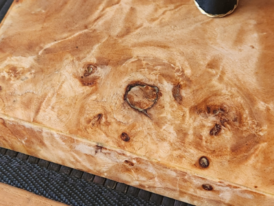
Burl naturally has a lot of holes. These are repaired by cutting out pieces of burl from offcuts and patching them in. Some holes are too small to be patched, so they were filled with a mixture of sawdust and PVA. The whole thing was sanded down to 400 grit, then my intention is to lay 8 coats of Tung Oil. On ship models, I normally lay only one coat which is sufficient. But with furniture, each successive coat adds protection and changes the appearance from matt to satin to semi-gloss. It will take 8 days to apply 8 coats, and this will be followed by burnishing (essentially a fancy name for sanding the last coat while it is still semi-wet with sandpaper starting at 400 grit down to 4000 grit). This will hopefully leave me with a nice semi-gloss finish. I am currently on day 2 of the process and it already looks incredible.
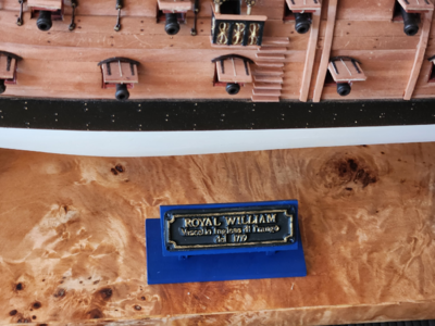
I made a little stand for the nameplate that came with the kit, although I might replace this with an engraved or etched copper plate some time in the future.
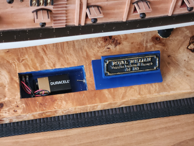
The nameplate can be removed which gives access to the battery and the switch for the electronics.
So - 6 days just to glue up the board, and another 8 days to varnish + 1 day filling burls and sanding. That's 2 weeks just for a simple plinth. It gives me new respect for furniture makers, it would be so much harder to make a table out of this stuff than a plinth.
Anyway, as mentioned earlier, the build has stalled due to lack of sufficient rope for rigging. So I constructed a plinth to replace the stand provided by Euromodel:

There is nothing wrong with the stand, it is sturdy, made of nice wood, and does the job. But ... I needed a way to route power into the model for the lights, and the Euromodel stand would leave wires dangling out in plain sight. So I constructed my own stand:

This is 3mm brass rod, bent on a vice and soldered. A thick stainless steel bolt goes through the middle and into a nut I installed in the false keel very early on in the build. The washer for the bolt has connections to the battery soldered on it. The whole assembly is pleasingly solid and holds the ship up no problem.

My initial idea was to sculpt a sea monster that is commonly illustrated in maps of the period out of Sculpey, thus hiding the stand and the steel bolt. I needed to make 4 of them. However, after making the first one, I mounted it on the base and found that it was far too large and it called too much attention to itself. It wouldn't be a stand for a model ship any more, instead it would be a stand with a model ship on top. So I scrapped the idea and went for a simpler stand.

This is what I ended up with. I simply painted over the brass and constructed a plinth from plywood. I then covered the plinth in a burl veneer.
If you have never used a veneer before, let me tell you this is a completely different kettle of fish. I thought it would be pretty easy, after all planking is nothing more than applying veneer to a frame, right? Wrong! Step 1 is to find a suitable veneer. I was fortunate enough to find Australian Premium Veneers, not far from where I live. I made an appointment and visited them, and bought two sequential sheets of Mappa Burl for AUD$39 each. Step 2 is to flatten the veneer - the wild figurations of the veneer means that it is a warped mess when you receive it. Spray it with water, and sandwich it between two boards for 24 hours. Once it is flattened, it will start to curl up again if not used within the next few hours. I diluted some PVA with water (70% PVA, 30% water) and brushed it on. I then sandwiched it between the two boards again with some cling wrap in between, and waited another 24 hours. Then it was time for the sides, and you guessed it - 24 hours for each side waiting for it to dry. That's 6 days on the plinth already, just waiting for wood or glue to dry. Sandwiching glued up boards dramatically slows down the rate that glue cures.
Then it was time to move to repairing the burl.

Burl naturally has a lot of holes. These are repaired by cutting out pieces of burl from offcuts and patching them in. Some holes are too small to be patched, so they were filled with a mixture of sawdust and PVA. The whole thing was sanded down to 400 grit, then my intention is to lay 8 coats of Tung Oil. On ship models, I normally lay only one coat which is sufficient. But with furniture, each successive coat adds protection and changes the appearance from matt to satin to semi-gloss. It will take 8 days to apply 8 coats, and this will be followed by burnishing (essentially a fancy name for sanding the last coat while it is still semi-wet with sandpaper starting at 400 grit down to 4000 grit). This will hopefully leave me with a nice semi-gloss finish. I am currently on day 2 of the process and it already looks incredible.

I made a little stand for the nameplate that came with the kit, although I might replace this with an engraved or etched copper plate some time in the future.

The nameplate can be removed which gives access to the battery and the switch for the electronics.
So - 6 days just to glue up the board, and another 8 days to varnish + 1 day filling burls and sanding. That's 2 weeks just for a simple plinth. It gives me new respect for furniture makers, it would be so much harder to make a table out of this stuff than a plinth.
KeithW, this is some beautiful work! I'm just getting started in my journey, though regretting I didn't do it sooner. I plan on a few "smaller" ships to build my experience, but I can realistically see retirement not too far in the distance now, and THIS is truly an inspiration of something I'd like to sink my teeth into when that time comes.
And BTW, thanks for showing those little Vanguard Boats... I've just ordered one w/oars to replace my kit's cheap-o pot metal version. They are reasonably priced for what they are, until you add shipping to the US. Anyway, I've spent more on much dumber things, and am looking very forward to getting it!
And BTW, thanks for showing those little Vanguard Boats... I've just ordered one w/oars to replace my kit's cheap-o pot metal version. They are reasonably priced for what they are, until you add shipping to the US.
 Anyway, I've spent more on much dumber things, and am looking very forward to getting it!
- Joined
- Jun 17, 2021
- Messages
- 1,653
- Points
- 488

Outstanding job,that's a master piece. it has a lot of details.Congratulations.
- Joined
- Jun 5, 2021
- Messages
- 141
- Points
- 88

Excellentes explications
Photos très bien réalisées
Merci beaucoup pour cette contribution
Un vrai régal
Marco
Photos très bien réalisées
Merci beaucoup pour cette contribution
Un vrai régal
Marco
Great job, R2D2 notwithstanding.View attachment 400704
The wales have gone on the ship. The vertical bend was first achieved by soaking the wood for 48 hours, and then clamping it tightly to a jig. Once dried, they have to be used within hours of being removed from the jig, otherwise they will straighten up again!
The lower wale was made from kit supplied walnut, dyed black. Once lightly sanded, the lustre of the walnut shines through the black.It is a marvellous (but totally unintended) effect. The walnut wale was incredibly difficult to get on. As noted by others, Feast Watson stains reject CA glue, even though they are water based! My first effort resulted in the wales falling off time and again until I thoroughly sanded off all the stain from the contact surfaces.
The upper wale was made from pear, which I milled from a block supplied by Hobbymill. Pear is a much nicer wood to work with - it is softer, finer grained, cuts cleanly, and much easier to sand. It was MUCH easier fitting the pear wales than the walnut thanks to its bending properties. My first attempt at finding the line of the upper wale involved tediously reading the plans, but then it was much easier to simply run a compass across the top of the lower wale.
Once done, the metal pieces were test fitted.
View attachment 400705View attachment 400706
This is a close-up of the metal pieces. You can see the difference between the metal pieces at the stern (which I have cleaned of all moulding flash), and the metal pieces at the bow, which I have not yet touched. Note that the total length of the pieces is more than adequate to cover the length of the ship, even will the side strakes taken into account.
Having done all that, I started work on the deck furniture.
View attachment 400707
I was not happy with the kit supplied capstan, so I turned my own on the lathe. It took me all day to make a capstan. Why?
View attachment 400708
Because of numerous failures and because i'm still learning how to use my lathe properly! Here are the failures lined up before my final successful attempt on the right.
View attachment 400709
I also fabricated the ship's stove. Note that I have deviated from the plans suggested by Euromodel. Euromodel suggests that the chimney is square and opens up directly to the sky. This means that any rain or seawater will fall directly into the fire, quenching it. My research suggests that chimneys were angled rearwards, and had a moveable cover - so that's what I made.
The rest of the stove will be hidden below deck, so I did not bother detailing the stove very much. There IS detail from where the stove can potentially be seen - from the back (peeking below the deck), from the top (through the grating), and from the side (through the gunports). But the front of the stove is pretty much left as it is.
The "bricks" that the stove is sitting on is simply painted plastic. I could have done a much better job if I had used masking tape, but I decided that nobody is ever going to see my shoddy paintwork, so I painted the bricks freehand.
View attachment 400710
I have also made a start on the gun carriages. I first attempted to make these on the milling machine, but after cranking those knobs I became fed up very quickly. It was MUCH faster to make them on the table saw!
View attachment 400711
The scratchbuilt gun carriages have been completed - along with eye rings, simulated rivets, and quoin. The quoin handles were made from the heads of the smallest belaying pins I could find at my hobby shop (Float-A-Boat). At $2 for a pack of 10, this sure beat trying to turn them myself.
View attachment 400712
A comparison of the kit supplied gun carriage and the scratchbuilt version with my 1/72 scale Android. You can see that it is exactly the same size and height. I ignored the suggested dimensions in the plans because I located the height of my gunports using the kit supplied carriage. This meant that I had to take the measurements off the kit supplied gun carriage but use a design which I completely copied from Chuck Passaro's practicum on MSW.
You may wonder why there is a red stripe there. The answer - it makes it much easier to paint later. I painted the plank and installed it. That way, you get a nice, sharp line without having to mask. I haven't gotten around to painting the rest yet.
You can also see that I have pre-drilled the holes for the gun rigging ... BEFORE the second planking layer goes on. This was a bit of foresight to prevent accidentally drilling holes from the inside to the outside and ruining the outside finish.
View attachment 400713
I decided to scratchbuild the decoration that goes above the front bulkhead as well. Two strips of pear were cut with the table saw, then run through the thickness sander until they were 1.8mm thick each. They were then lightly glued together with PVA (generic PVA, NOT Titebond!). The required outline was drawn out in pencil, then they were carved together. After this, it was mounted on my mill to drill 40 holes, spaced 4mm apart (I do not own a drill press). This ensured that they were exact duplicates. They then were soaked in water. This dissolves the PVA and the pieces came apart.
View attachment 400714View attachment 400715
The balustrades were formed with my "bead on a wire" trick described earlier. They were then painted with metal primer (Admiralty paints), then painted gold (Vallejo Old Gold). After 24 hours curing time, they were pushed into the holes drilled earlier and secured with CA.
This is a comparison of the scratchbuilt decoration compared with the part supplied by Euromodel. I think the scratchbuilt version looks miles better!
View attachment 400716
I started work on the front bulkhead and the "seats of ease". Measurements were taken from the ship, then a ply template was created. I progressively shaved off wood until it fit the front bulkhead exactly. Here you can see two attempts - the first attempt was created before I realized that I had forgotten to take into account the camber of the fo'c'sle deck! Back to the drawing board, had to make another one.
The seats were formed by cutting a 12mm dowel 60/40, and using the thicker piece. The windows for the seats of ease were turned from aluminum stock on my lathe. I am getting quite good at this now, I have to say! The walls of those round windows are 0.3mm thick!
View attachment 400717
Front bulkhead completed and painted.
View attachment 400718
For other RW builders: this is how the front bulkhead is located with regards to Frame 8. Note my mistake with terminating the planking early (earlier posts describe how I fixed it, but I didn't fix it enough). No matter, the second planking will be brought to the level of the front bulkhead and nobody will be any wiser.
View attachment 400719
The front bulkhead dry fitted on the ship.
Are the carriage blocks to scale?From here on, I am on to the "easy" part of the build, where I am adding details and not structural elements. Anything I do from here can be rectified if I make a mistake. In a sense, this is much more relaxing than having to measure and triple measure parts which have not been created yet or attempt to visualize how something that can not be supported is going to fit. I have made everything fit through my own solution - by scratchbuilding parts so I can guarantee that they fit.
I have completed all the gun carriages now. What started off as fun when I did the first one quickly became tedious after having to do so many. Fortunately, I made a gun carriage rigging jig that made my life easier:
View attachment 400844
It is just a simple jig I threw together from spare kit plywood with holes drilled in it. You can see the features of the jig: there is a square hole that allows me to work on that block from the bottom. I made all the ring bolts oversized so I just push the bolt through the hole, bend the wire at the back, and it holds it secure while I pull on the ropes. There are also brass rods which allow me to make rope coils.
You can see that I am using my own scratch built gun carriages instead of the supplied kit carriages which are too square and do not have the tapering angles found on real gun carriages.
View attachment 400845
Once rigging is finished, simply pull all the ringbolts out of the holes and it is ready for mounting on the ship.
View attachment 400848
Here is one of them, mounted on the ship. I had 30 of these to make, I estimate it took me 2 hours per gun carriage. 3-4 hours to mill all the parts, another 4-5 hours to make all the ringbolts and tackle, 30 min per carriage to assemble, 45 min per carriage to rig, and 10 min per carriage to mount. Then there are the guns which took me a few hours to clean and blacken. I will wait until more of the hull is completed before I mount the guns.
It took a lot longer than 10 minutes for tricky carriages like this one which are under the gangway. I rehearsed talking like a sailor when attempting to push pins into holes that I could barely see. I don't know what I was thinking when I installed the gangway before making the carriages - so other RW builders, don't do this!
For historic accuracy I should have painted the carriages red. But I do like the look of pear, so I left them in natural wood.
I was not happy with the appearance of the belfry as supplied with the RW kit. It appears to be taken from the model of the RW at the National Maritime Museum in Greenwich, UK. This is a photo of the belfry that I took when I visited Greenwich a few years ago:
View attachment 400849
However, the model at the USNA museum is much more ornate:
View attachment 400850
So, I pondered how I am going to replicate that, given that carving it is beyond my skill level. I came up with this solution ... I don't know if I have invented a new modelling technique.
View attachment 400851
What you need is some tinfoil, CA glue, and a mold to form the shape around. My idea was to laminate multiple sheets of foil with CA glue around the mold. The mold was made by taking a dowel, splitting it in half, and then carving out the underside of one of the dowels so that the other half could fit. A Dremel with a drum sander makes easy work of it.
View attachment 400852
Rub the mold liberally with vaseline (in case the foil tears and CA sticks the foil to the mold!). Then lay the first layer of foil on top and gently work around the curves with a Q-tip cotton bud. Once nicely pressed, apply a liberal layer of CA glue. It needs to be slow curing!
View attachment 400853
I did 7 layers of tinfoil, then left it alone for a couple of hours to make sure the CA glue really sets. Cut it out and Dremel it into shape. At this point, it is what you expect 7 layers of laminated alfoil to be - it is really light, but stiff enough to handle. But it is not super tough and it WILL deform if you do not handle it delicately. But ... it's a belfry. It is not a structural component (where strength is important), and I do not anticipate anybody is going to touch it. So it will do.
View attachment 400854
After I sprayed it with metal primer, I painted it. This is the result, compared to the Euromodel supplied belfry.
I purchased the bell from a model shop. It is turned brass and much nicer than the cast white metal bell supplied with the kit.
- Joined
- Apr 11, 2015
- Messages
- 92
- Points
- 103

Are the carriage blocks to scale?
No, they are much too big. I have smaller blocks, but I found them a bit too small for my poor eyesight / limited skills so these are the ones I went with. Maybe I should have foregone using the blocks, it might look better.
I skipped the blocks on my Connie. The guns were just too tiny. Just used breaching ropes.No, they are much too big. I have smaller blocks, but I found them a bit too small for my poor eyesight / limited skills so these are the ones I went with. Maybe I should have foregone using the blocks, it might look better.
- Joined
- Jun 17, 2021
- Messages
- 1,653
- Points
- 488

Phew! I'm Exhausted!
I hope you are as proud of your work as you well deserve to be. That goes double for going above and beyond the call of duty during the especially trying first year of covid.
It's a privilege to follow along.
Pete
I hope you are as proud of your work as you well deserve to be. That goes double for going above and beyond the call of duty during the especially trying first year of covid.

It's a privilege to follow along.
Pete
- Joined
- Apr 11, 2015
- Messages
- 92
- Points
- 103

I have good news and bad news. The good news: the rope that I ordered from Syren in the USA has finally arrived. The bad news: now I have to do the rigging. I HATE rigging, it is the most tedious and frustrating job. Rope never goes where it's supposed to, it has a tendency to untie itself, I have to be careful not to damage the model. I know some people love rigging, and I am trying to convince myself to love it to make the job less painful.
Anyway, I borrowed a rope server from a friend. It is a really impressive machine:
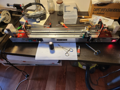
Note it has two motors - one to turn the rope you are serving, the other to feed serving string. Both motors have individual controls for on/off, speed, clockwise/counterclockwise, and forward/reverse. I am sure it would work really well, but I ended up feeding the string manually because of the setup time involved. The alligator clips soldered on brass rod was my modification, it is supposed to work via collets at each end, which meant there was a minimum length of rope that can be worked on.
I have finished serving all the lower shrouds, with the first shroud served across its entire length. This was done to stop sails from chafing the shrouds. You might notice that the foremast shrouds are a little short, this was because I did not order enough rope from Syren and I was trying to economize. I juuust made it, and the ropes are juuust long enough to rig.
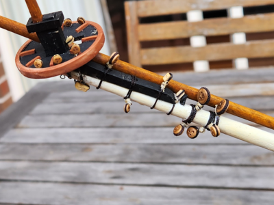
I have also installed all the blocks on the bowsprit. I think that's all of them. I hope!
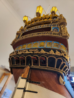
Since I ordered extra guns from Euromodel, I had many spares sitting around. Earlier in my build I excavated some holes in the lower transom to accommodate guns, but I forgot to install them. They are now installed. This view of the underside of the transom is hopefully something nobody will ever look at since it is full of mistakes. You can see where I had to shim the decks because I cut them a little too short. You can barely see it from above, at normal viewing angle ... but at the bottom it is quite obvious.
I am short of a few blocks and a chain for the rudder. I am making up another shopping list for another online order ...
Anyway, I borrowed a rope server from a friend. It is a really impressive machine:

Note it has two motors - one to turn the rope you are serving, the other to feed serving string. Both motors have individual controls for on/off, speed, clockwise/counterclockwise, and forward/reverse. I am sure it would work really well, but I ended up feeding the string manually because of the setup time involved. The alligator clips soldered on brass rod was my modification, it is supposed to work via collets at each end, which meant there was a minimum length of rope that can be worked on.

I have finished serving all the lower shrouds, with the first shroud served across its entire length. This was done to stop sails from chafing the shrouds. You might notice that the foremast shrouds are a little short, this was because I did not order enough rope from Syren and I was trying to economize. I juuust made it, and the ropes are juuust long enough to rig.

I have also installed all the blocks on the bowsprit. I think that's all of them. I hope!

Since I ordered extra guns from Euromodel, I had many spares sitting around. Earlier in my build I excavated some holes in the lower transom to accommodate guns, but I forgot to install them. They are now installed. This view of the underside of the transom is hopefully something nobody will ever look at since it is full of mistakes. You can see where I had to shim the decks because I cut them a little too short. You can barely see it from above, at normal viewing angle ... but at the bottom it is quite obvious.
I am short of a few blocks and a chain for the rudder. I am making up another shopping list for another online order ...
Thats going to be a real showpiece when finished Keith. I must come visit you and see it up close.
I feel your pain on the rigging. On my Soleil Royal, I spent hundreds of hours on the rigging. You can hardly notice it now unless you look closely. And who can tell if it’s done correctly since there are sooo many lines going every which way. Just keep plugging away. It will be a beautiful model.


