Wonderful Keith! I fancy this ship myself so I'll pull up a chair as you get caught up with your postings...
You are using an out of date browser. It may not display this or other websites correctly.
You should upgrade or use an alternative browser.
You should upgrade or use an alternative browser.
HMS Royal William 1719, Euromodel, 1:72
- Thread starter KeithW
- Start date
- Watchers 18
-
- Tags
- euromodel royal william
WOW ..... and Bravo
a highly interesting building log, full of information and tipps
showing very good workmanship
I will follow your further work / log with big interest
a highly interesting building log, full of information and tipps
showing very good workmanship
I will follow your further work / log with big interest
- Joined
- Apr 11, 2015
- Messages
- 92
- Points
- 103

It really isn't anything amazing, there is another Royal William currently under construction in SOS by Oleg. Now THAT ONE is amazing. This is a far more pedestrian effort, but it is the best I can do given my limited skills. Anyway, I will continue to migrate posts.
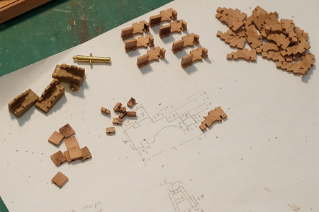
Fabricating replacement cannon carriages. This had to be done because a pair of cannon carriages have to be installed before the poop deck goes on. I explained how I did it several posts ago. On the left are kit supplied carriages. On the right are my scratchbuilt ones under construction.
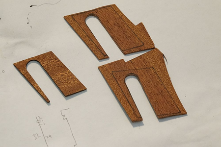
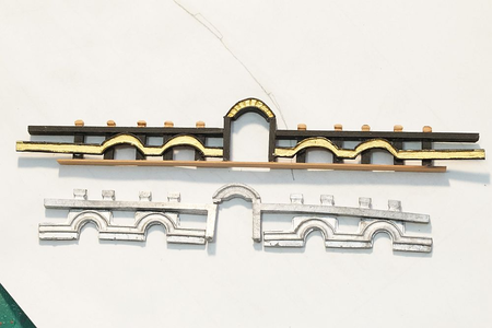
Because my deck features are a slightly different size to the Euromodel supplied parts (but correct according to the plans), I had to construct a new archway using the kit supplied archway as a template.
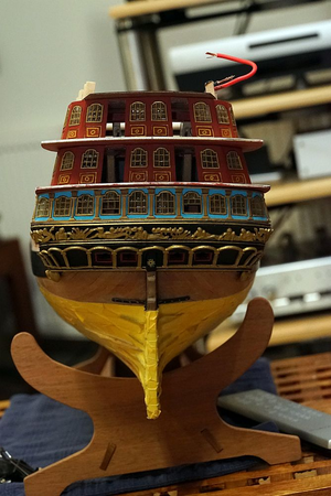
The top gallery, seen in the previous post under construction, has now been completely veneered over and the windows have been installed.
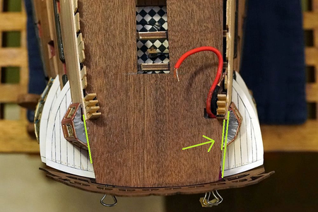
Whilst checking the poop deck for fit, I noticed that the hindmost part of the deck was off by 1mm! Not much, but enough to cause problems. The solution was to cut some material to bulk it up.
The real transom was dry fitted after I curved it with a steam iron. As you can see, it aligns perfectly with the poop deck ...
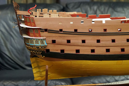
... and all the decks below.
The sharp eyed will notice that the rearmost gunports have been closed over. This is because I positioned them incorrectly. The metal side decorations feature holes cut out for gunport locations! If your gunport holes are off by a fraction, they will not line up with the metal decorations! Mine were off by just 1mm. That's enough to make me close them over and cut them out again when I dry fit the side metal decorations.
The upper wales have been brought all the way back to the stern, with a tiny gap cut for metal decorations.
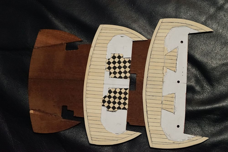
All the decks have been planked over, except the poop deck. I managed to salvage the deck I was planning to discard, turns out that I could remove the planks fairly easily. Wood glued to plastic isn't as secure as wood glued to wood - run a scalpel between the plank and the styrene structure, and the plank just pops off. It leaves quite a bit of CA residue, but that is easily scraped off.
Other RW builders will note that the shape of the decks is quite different to that given by Pete in his Interpretive Info. The shape of the deck was arrived by placing the poop deck (which has the correct curvature) on a piece of paper, and Part 53 on either side of it until the rear edges are flush with the poop deck. From that, I traced a line. That gives me the rear line of the deck. For each deck, I placed Parts 51, 52, and 53 respectively. I drew and built the deck slightly oversized - I then placed them on a model then used a ruler to line them all up and shaved them back. Finally, the transom was dry fitted and further adjustments made.
You can also see how the decking material accomodates the openings for the doors. You can just catch a glimpse of the interior with the doors slightly ajar, so I did not have to veneer over the whole inside deck.
The contours of the planks follow the galleries closely. Slide a gallery over the deck, and it will fall into the planks with a satisfying pop.
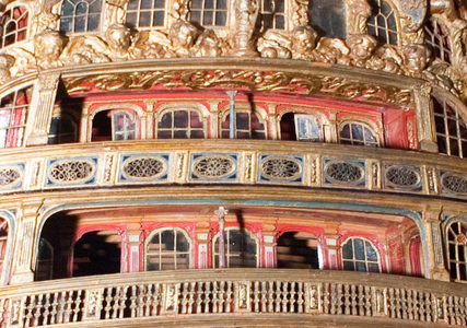
If you study the rear of the USNA model of the Royal William, you will notice a few features that Euromodel's plans do not have, and make no provision for in the kit.
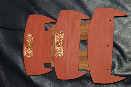
One of them is ceiling decorations and a center column. I have added the decorations. It is nowhere near as elaborate as the USNA model, but good enough in my opinion. I have also turned some columns on my lathe (not pictured). The circle in the center is to hold the columns once they are installed.
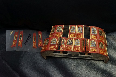
The galleries have had most of the column decorations added. The last set of columns will be added once I determine the position and angle of the archways (depicted in the previous post). This is surprisingly complex - when I get around to doing so, I will make a post about it.
Next to the galleries is a picture of my doors, yet to be cut out. You can see that the doors are assembled on a piece of acetate. A diagram of the door is drawn on paper, then a strip of acetate is taped onto it. I then plank over the plastic and paint. When done, I just cut it out and install.
Here is a little video I took of the top gallery of the stern sliding on. The "pop" when the gallery clicks into place was so satisfying, I had to take a video to remember it.
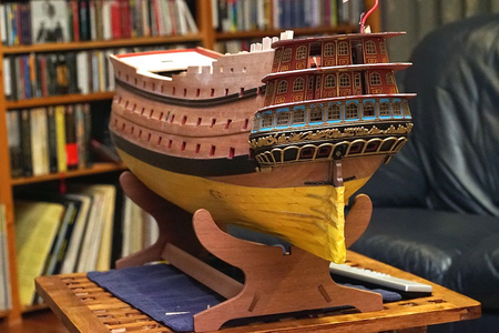
... and lastly, a couple of pictures of the model as she is. Probably about five more things to tick off my list, and then the poop deck goes on.

Fabricating replacement cannon carriages. This had to be done because a pair of cannon carriages have to be installed before the poop deck goes on. I explained how I did it several posts ago. On the left are kit supplied carriages. On the right are my scratchbuilt ones under construction.

Because my deck features are a slightly different size to the Euromodel supplied parts (but correct according to the plans), I had to construct a new archway using the kit supplied archway as a template.

The top gallery, seen in the previous post under construction, has now been completely veneered over and the windows have been installed.

Whilst checking the poop deck for fit, I noticed that the hindmost part of the deck was off by 1mm! Not much, but enough to cause problems. The solution was to cut some material to bulk it up.

The real transom was dry fitted after I curved it with a steam iron. As you can see, it aligns perfectly with the poop deck ...

... and all the decks below.
The sharp eyed will notice that the rearmost gunports have been closed over. This is because I positioned them incorrectly. The metal side decorations feature holes cut out for gunport locations! If your gunport holes are off by a fraction, they will not line up with the metal decorations! Mine were off by just 1mm. That's enough to make me close them over and cut them out again when I dry fit the side metal decorations.
The upper wales have been brought all the way back to the stern, with a tiny gap cut for metal decorations.

All the decks have been planked over, except the poop deck. I managed to salvage the deck I was planning to discard, turns out that I could remove the planks fairly easily. Wood glued to plastic isn't as secure as wood glued to wood - run a scalpel between the plank and the styrene structure, and the plank just pops off. It leaves quite a bit of CA residue, but that is easily scraped off.
Other RW builders will note that the shape of the decks is quite different to that given by Pete in his Interpretive Info. The shape of the deck was arrived by placing the poop deck (which has the correct curvature) on a piece of paper, and Part 53 on either side of it until the rear edges are flush with the poop deck. From that, I traced a line. That gives me the rear line of the deck. For each deck, I placed Parts 51, 52, and 53 respectively. I drew and built the deck slightly oversized - I then placed them on a model then used a ruler to line them all up and shaved them back. Finally, the transom was dry fitted and further adjustments made.
You can also see how the decking material accomodates the openings for the doors. You can just catch a glimpse of the interior with the doors slightly ajar, so I did not have to veneer over the whole inside deck.
The contours of the planks follow the galleries closely. Slide a gallery over the deck, and it will fall into the planks with a satisfying pop.

If you study the rear of the USNA model of the Royal William, you will notice a few features that Euromodel's plans do not have, and make no provision for in the kit.

One of them is ceiling decorations and a center column. I have added the decorations. It is nowhere near as elaborate as the USNA model, but good enough in my opinion. I have also turned some columns on my lathe (not pictured). The circle in the center is to hold the columns once they are installed.

The galleries have had most of the column decorations added. The last set of columns will be added once I determine the position and angle of the archways (depicted in the previous post). This is surprisingly complex - when I get around to doing so, I will make a post about it.
Next to the galleries is a picture of my doors, yet to be cut out. You can see that the doors are assembled on a piece of acetate. A diagram of the door is drawn on paper, then a strip of acetate is taped onto it. I then plank over the plastic and paint. When done, I just cut it out and install.
Here is a little video I took of the top gallery of the stern sliding on. The "pop" when the gallery clicks into place was so satisfying, I had to take a video to remember it.

... and lastly, a couple of pictures of the model as she is. Probably about five more things to tick off my list, and then the poop deck goes on.
- Joined
- Apr 11, 2015
- Messages
- 92
- Points
- 103

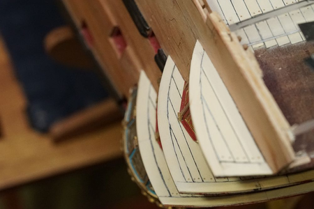
All the decks seem to line up nicely.
RW builders will note that I have built in a feature that I have seen in museum models but not in Euromodel's plans.
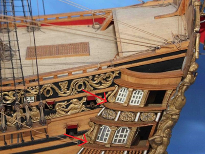
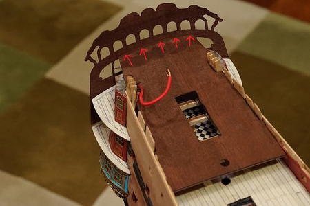
This picture was taken from Euromodel's website. The red arrows show the galleries sitting flush on top of the railings. The plans suggest the same.
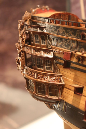
However, the stern from the NMM's model of the RW does not agree ...
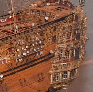
... and neither does the model in the USNA.
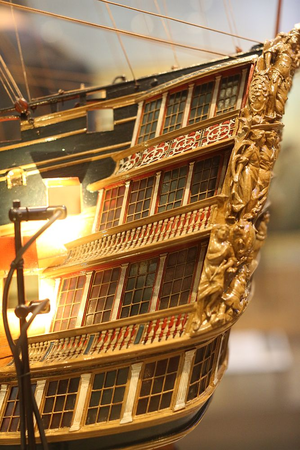
This is not the RW but the fourth HMS Victory (launched in 1737) - again showing that the galleries are not flush with the railings.
I decided to extend the decks rearwards and give them a different profile to that suggested by the plans so that the railings would clear the galleries. Unfortunately, this means that the metal decorations may not fit ... so i'll have to do some surgery on those decorations later.
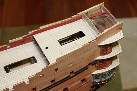
Poop deck is finally on!
I am now constructing the poop cabin. The fact that I am planning to light it is posing all sorts of problems and making me find different solutions to what would normally be a standard build. For example, the internal support structures are 3mm thick perspex instead of wood which I would normally use. I have to do this so that light gets through.
After finishing the stern galleries, I should proceed to install the transom. However, because I am going to light the lanterns, I would have to install the lanterns as well. The thought of working on the rest of the ship while the fragile lanterns hang off the stern made me decide to put it off for now. I will finish all the major woodwork on the ship first, and then return to the stern.
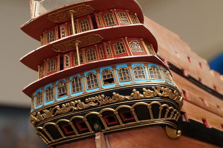
A bottom view of the stern, showing off the ceiling decorations and the column.
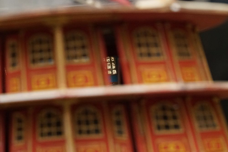
You can catch a glimpse of the gallery in front if you look through the open door.
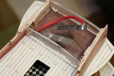
The internal reinforcement for the poop cabin is made from perspex. I should note that the metal part supplied by Euromodel appears to be lopsided - the curve on one half does not appear to match the curve on the other. I initally obtained the shape by tracing out Euromodel's part, but when I realized that the shape was a bit off, I ended up drawing my own shape.
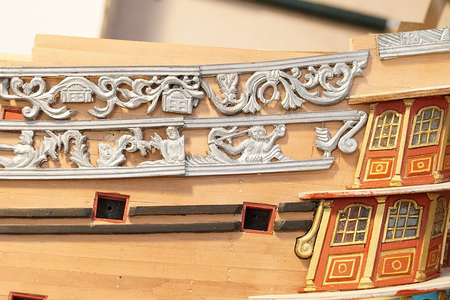
The decorations were dry fitted for testing.
The lower line for the decorations was obtained by using a compass and tracing a 10mm line above the wale below it. In fact, the lines for all the wales were obtained this way. I think it is important that all the wales are lined up, otherwise the model might look a little lopsided.
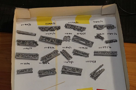
The metal decorations are all sorted, cleaned with acetone, painted with metal primer, and ready for painting.
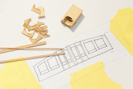
Construction of a replacement front face for the poop cabin is under way.
- Joined
- Apr 11, 2015
- Messages
- 92
- Points
- 103

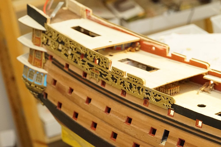
Having decided to put off the transom for the time being, I am now installing the metal side decoration pieces. The lower limit of the decoration was determined by reading the plans - 1cm above the last wale. I simply took a compass, set it to 9mm, and drew a line exactly parallel to the last wale. I subtracted 1mm because the black line will be hidden under the metal decoration and I wanted some leeway.
Other RW builders will note that the plans call for the side of the hull to cut exactly at the termination of the poop deck. I did not think that this would look very nice so I made sure that I had at least 1mm to play with.
Each metal piece needs to be shaped to conform to the hull, with holes cut out for gunports. Initially I used a Dremel with a cutting wheel, until I found out that a pair of Xuron nippers did a much faster and neater job. It does leave a nipping mark, but this is easily cut off with a scalpel. Oh yes, the metal is soft enough to be carved with a sharp scalpel!
You will also note that the side window (Euromodel part 11260) has been replaced with a scratch built window. This is necessary to let the light from the LED's through. It also looks much better than the Euromodel supplied part.
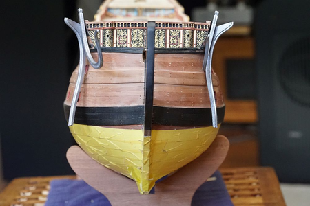
I have completed side decorations to the area of the fo'c'sle but decided to stop for the time being while I install the beakhead. I fabricated a replacement for the Euromodel supplied part. This is Mk. 1 of the piece - I do not like the look of the archways so I removed them. I will be fabricating another replacement soon.
Pins were soldered to the railings and holes drilled into the hull to accomodate. As you can see, the railings happily sit on the hull without any glue whatsoever.
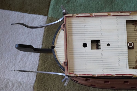
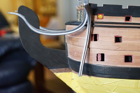
A cursory examination of the railings tells you how much they need to be bent to fit the beakhead ... and they need to be bent in three dimensions. Not going to be an easy task. I ended up screwing this up not once, but twice.
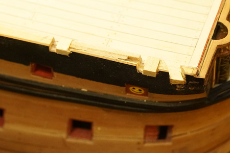
Having determined the position of the cathead support, I proceeded to cut out a hole for the cathead.
Uh-oh.
As you can see, the cathead will be much too close to the first gun, and this was despite cutting out the gun position exactly as per Euromodel's plans. Here you can see me moving the position of the gunport - glue in a filler block and recut the gunport.
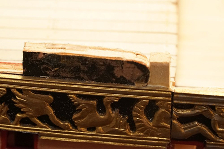
While i'm at it, I also found that I cut the starboard poop deck gunport FIVE MM short compared to port! As a result, the metal decoration does not quite fit. Here you can see the repair - remove the decoration, fill in the defect with a block, then re-install the decoration.
For those who have yet to cut out the gunports, you should take note that the position of some of these gunports is absolutely critical. Not all are.
Ideally, Euromodel should provide pre-cut plywood gunports, like other kit manufacturers. If they don't, they could supply a paper template - but they don't do that either. Instead, they supply plans. Whilst the plans are very good, they are a 2 dimensional representation of a 3 dimensional shape. As a result, the position of any features drawn in the plans which curves away from flat in the real ship can not be trusted.
Furthermore, what most RW builders have done is trace out the plans on tracing paper, then align the tracing paper on the model to cut out the gunports. This is not reliable either. I have multiple gunports which are off by as much as 10mm - in 1/72 scale terms, this is a massive error.
Fortunately, the position of most of these gunports don't matter very much. But a few of these gunports definitely matter, and I would like to draw your attention to them.
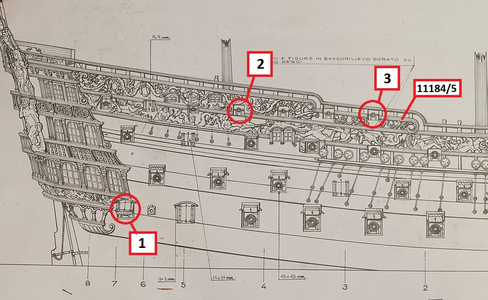
1. The position of this gunport should be located at the end of the transom support (Parts 54/55). It abuts, but does not cross Frame 7. Because this gunport does not open, I would suggest that this gunport not be cut out until the transom support is located. Otherwise your transom support might foul the gunport opening. This is not a discovery you want to make when your second planking and wales have already been installed. Fortunately, mine were correctly cut out.
2. This gunport is located immediately under the termination of the poop deck. As other posts have indicated, the length of the Euromodel supplied poop deck is incorrect when compared to the plans. Most of us have shortened the poop deck. If you do this, you will now find that the gun carriage which should be installed in this position will foul the curved staircase that should be installed.
If you have an eye for this kind of detail, I invite you to look at all the pictures of Euromodel RW that you can find. You will see that this is a common mistake - a mistake that I also made. I had to fix my error by re-locating the gunport (install wood blocks, re-cut). Don't do what I did - learn from my mistake!
3. The position of this gunport on the second quarter deck should be exactly one length of metal part 11184/11185. You will see from my above post that I did not realize this. Fortuitiously, on one side of the ship the position of the gunport was exactly correct. On the other side, I was off by 5mm and had to make repairs.
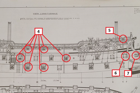
4. If you locate these gunports improperly, you will not be able to install the fenders. I realized this before the second planking went on, and I had to relocate a number of gunports to accomodate the fenders.
The fenders are 3mm wide. I suggest you cut a strip of 3mm wood and check that the position of your intended gunport does not foul the fender before you cut it out.
Take reference from the location of the side entrance. It should abut (but not cross) Frame 1.
5. If you do not take care in the location of this gunport, you will foul the cathead. Do not cut out this gunport until the location of the cathead has been determined.
6 and 7. Neither of these gunports have their position accurately marked in the plans. This part of the ship curves away thus the position can not be trusted. You will note that neither of these gunports can be opened, and the position is strongly influenced by the position of the beakhead railings. I suggest you do not cut out these gunports until you have dry fitted the beakhead railings.
With the rest of the gunports, you can have an error of a few mm and up to 1cm but it won't prevent you from installing any features. These are the only gunports you need to worry about.
- Joined
- Apr 11, 2015
- Messages
- 92
- Points
- 103

Here are a few vanity shots ... just for fun.
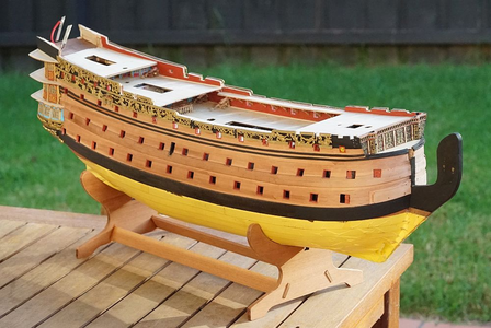
Taken in the backyard on an Australian winter morning. Yes, the sun is out. Grass is green, and the sky is blue. But it is really cold!!
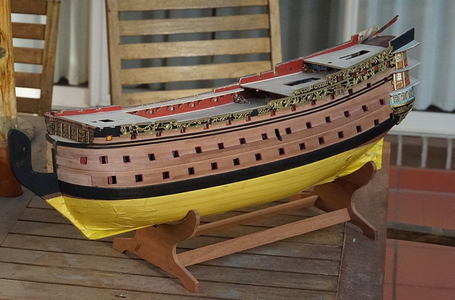
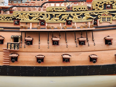
The other side. Decorations have been placed all the way to the front with the exception of the last piece. Once the beakhead railings go on, the last piece will be placed. The position of all the gunport holes have been finalized and cut out.
Note also the gaps in the decorations that I left for the fenders. I have not shown a picture of the fenders yet, but they have been cut, sanded, and ready to be installed. Because the top of the fenders need to reach the cap railings, the top of the fenders have not been trimmed. I do not want to leave the tops sticking out while I work on the rest of the ship, so I will leave off installing the fenders until I am ready to install the cap railings - which will come after the transom is completed.
You can also see that the pear planking in the front is a lighter shade than the rest of the ship. This is because it has been freshly sanded in preparation for the beakhead railings to go on. The darker shade of pear is what pear looks like when it has not been sealed and has been absorbing oil from my fingers for more than a year.
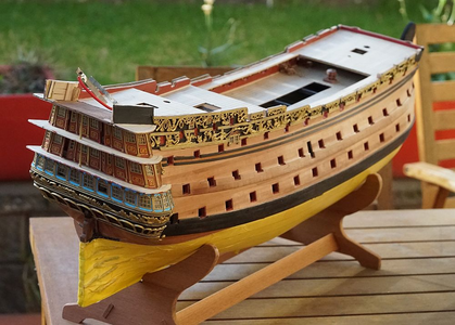
From the back. You will note that the top of the decorations look a little irregular. Can't be helped, that is the nature of what was supplied in the kit. Once the wooden caps go on, everything will be sanded until it is flat.
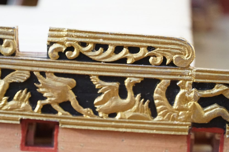
The completed repair of the re-positioned gunport I showed in my previous post. I saved all the offcuts from the decorations in case I might need them. In this case, I lengthened the decoration by gluing in parts that I had to remove from other pieces to accomodate gunports and so on.
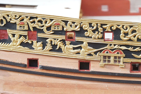
Close up of the three windows which I replaced. In hindsight I could have left on Euromodel's supplied smaller windows instead of removing them - they are barely noticeable when the model is viewed in full. And my replacement doesn't look that great.
You can also see that I have filled in the gaps between the decorations with some epoxy putty and painted it over. Keith Julier says that the joints are almost invisible once you do this. Well, i'm no Keith Julier so my joints are still visible! I will probably go and sand them back a bit more to see if I can improve on this.

Taken in the backyard on an Australian winter morning. Yes, the sun is out. Grass is green, and the sky is blue. But it is really cold!!

The other side. Decorations have been placed all the way to the front with the exception of the last piece. Once the beakhead railings go on, the last piece will be placed. The position of all the gunport holes have been finalized and cut out.
Note also the gaps in the decorations that I left for the fenders. I have not shown a picture of the fenders yet, but they have been cut, sanded, and ready to be installed. Because the top of the fenders need to reach the cap railings, the top of the fenders have not been trimmed. I do not want to leave the tops sticking out while I work on the rest of the ship, so I will leave off installing the fenders until I am ready to install the cap railings - which will come after the transom is completed.
You can also see that the pear planking in the front is a lighter shade than the rest of the ship. This is because it has been freshly sanded in preparation for the beakhead railings to go on. The darker shade of pear is what pear looks like when it has not been sealed and has been absorbing oil from my fingers for more than a year.

From the back. You will note that the top of the decorations look a little irregular. Can't be helped, that is the nature of what was supplied in the kit. Once the wooden caps go on, everything will be sanded until it is flat.

The completed repair of the re-positioned gunport I showed in my previous post. I saved all the offcuts from the decorations in case I might need them. In this case, I lengthened the decoration by gluing in parts that I had to remove from other pieces to accomodate gunports and so on.

Close up of the three windows which I replaced. In hindsight I could have left on Euromodel's supplied smaller windows instead of removing them - they are barely noticeable when the model is viewed in full. And my replacement doesn't look that great.
You can also see that I have filled in the gaps between the decorations with some epoxy putty and painted it over. Keith Julier says that the joints are almost invisible once you do this. Well, i'm no Keith Julier so my joints are still visible! I will probably go and sand them back a bit more to see if I can improve on this.
- Joined
- Apr 11, 2015
- Messages
- 92
- Points
- 103

It was at this point (in 2017) that progress stopped on my model. Life got in the way - promotion at work meant I was far more busy than before, illness in the family, and so on. Unlike many of you, COVID made me even busier with work and I was spending a lot of time in the hospital (working, not being sick!). COVID was a total catastrophe for those in my profession, and I have never worked such long hours or till so late, and it was horrifying how little we could do and how helpless we were. Fortunately the virus has mutated now and is far less dangerous than before.
During this time, the model sat in the state that you see above in my living room. It was still magnificent and amazing, and visitors would wow at it and tell me that I should finish it. Well, I have a bit of time this year having decided to take a sabbatical from work burnout, so I got back to work.
This build log was restarted on the 27th of October this year.
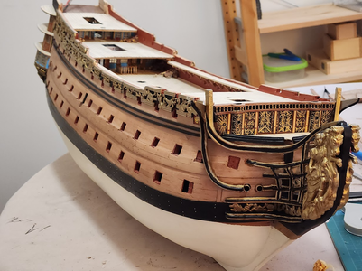
My previous progress was stalled because I had cut the beakhead supports (I don't know what you call them, those vertical riser things?) wrongly. Euromodel only supplies 6 - which is just enough if you don't make any mistakes. I had to source a set of spares from a friend who had abandoned his RW build and this time I carefully cut them out and installed them. I am not entirely pleased with the result but it looks OK.
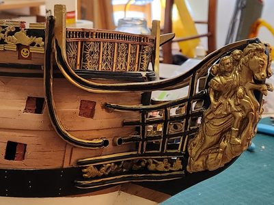
Hand painting the beakhead was very difficult since my eyesight is not as good as it was a few years ago. I went back and fixed some of the jaggies so it looks better.
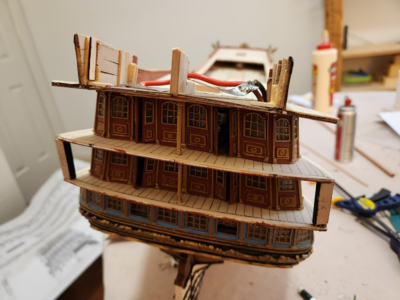
I am now working on the transom. It is difficult to support the fascia piece and I was concerned about the lack of gluing points for the heavy decorations that would hang off it, so I installed some columns on either edge of the lower deck. These are pinned to the decks above and below and are absolutely solid. These will be hidden by the metal castings and the fascia piece, and when the fascia is installed I will drill a hole through it and pin it.
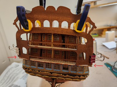
With the support columns in place, it allows me to clamp the fascia piece onto the transom and allows me to work on the position with much greater precision and repeatability than before. I had already pre-curved the fascia a few years ago and marked the center line alignment. Once installed, all the horizontal bars will be cut out and replacements will be fabricated.
I indicated with arrows some gaps where the rear fascia is not quuuuite long enough to meet the decks. I will need to add some material to this. There is not much gluing area, fortunately I was planning to add some reinforcement behind it to help support the weight of the transom anyway.
This is the most exciting part of the kit - the major reason I bought the Royal William was because of the open stern galleries which lends a lot of visual excitement. I am taking reference off other RW kit builders (most of whom have finished their models) and photos I have found online. My stern will have a different colour scheme because I do not think that painting it all black is correct. I will post again when I have completed more work.
During this time, the model sat in the state that you see above in my living room. It was still magnificent and amazing, and visitors would wow at it and tell me that I should finish it. Well, I have a bit of time this year having decided to take a sabbatical from work burnout, so I got back to work.
This build log was restarted on the 27th of October this year.

My previous progress was stalled because I had cut the beakhead supports (I don't know what you call them, those vertical riser things?) wrongly. Euromodel only supplies 6 - which is just enough if you don't make any mistakes. I had to source a set of spares from a friend who had abandoned his RW build and this time I carefully cut them out and installed them. I am not entirely pleased with the result but it looks OK.

Hand painting the beakhead was very difficult since my eyesight is not as good as it was a few years ago. I went back and fixed some of the jaggies so it looks better.

I am now working on the transom. It is difficult to support the fascia piece and I was concerned about the lack of gluing points for the heavy decorations that would hang off it, so I installed some columns on either edge of the lower deck. These are pinned to the decks above and below and are absolutely solid. These will be hidden by the metal castings and the fascia piece, and when the fascia is installed I will drill a hole through it and pin it.

With the support columns in place, it allows me to clamp the fascia piece onto the transom and allows me to work on the position with much greater precision and repeatability than before. I had already pre-curved the fascia a few years ago and marked the center line alignment. Once installed, all the horizontal bars will be cut out and replacements will be fabricated.
I indicated with arrows some gaps where the rear fascia is not quuuuite long enough to meet the decks. I will need to add some material to this. There is not much gluing area, fortunately I was planning to add some reinforcement behind it to help support the weight of the transom anyway.
This is the most exciting part of the kit - the major reason I bought the Royal William was because of the open stern galleries which lends a lot of visual excitement. I am taking reference off other RW kit builders (most of whom have finished their models) and photos I have found online. My stern will have a different colour scheme because I do not think that painting it all black is correct. I will post again when I have completed more work.
- Joined
- Apr 11, 2015
- Messages
- 92
- Points
- 103

I was not happy with the way I installed the beakhead supports / vertical risers.
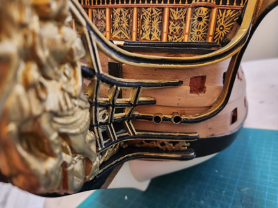
So I pulled them out and reinstalled them:
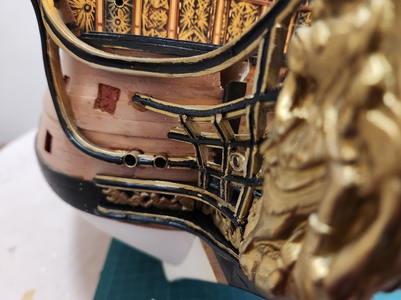
I will need to sand off all the glue marks and repaint it. I am not happy with how lumpy the final appearance looks. The problem is that the metal is so soft, and when I shape them on my disc sander the only way to get a proper grip on the piece is to hold it with pliers. This then leaves a mark on the piece. I should have used good old hand sanding instead to shape the piece but that takes forever!
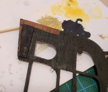
In a previous post, I showed that the pre-cut plywood fascia does not fit my model. So I had to graft an extension on to it. You can see a faint line from the front, but it won't matter because it will be covered by decorations.
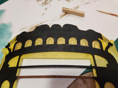
With that complete, I made a start with the windows. Euromodel supplies cast metal windows. Other modellers have drilled out the window panes and filled it with clear glue to imitate glass. Given that the rest of the windows and panels are scratch built in my model, I had to continue the same approach.
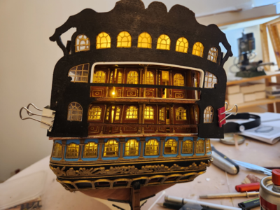
After I completed all the windows, a quick test to show if the lights are still working after leaving the ship untouched for a few years. All good!
They have a wonderful "scratch built" look to them. By that I mean, they are inconsistent from one window to another. If it's too perfect then it looks like it came from the kit Having said that, I think these look better than the kit supplied windows. There is more glass area, the windows are bigger, and the details are ever so slightly finer.

So I pulled them out and reinstalled them:

I will need to sand off all the glue marks and repaint it. I am not happy with how lumpy the final appearance looks. The problem is that the metal is so soft, and when I shape them on my disc sander the only way to get a proper grip on the piece is to hold it with pliers. This then leaves a mark on the piece. I should have used good old hand sanding instead to shape the piece but that takes forever!

In a previous post, I showed that the pre-cut plywood fascia does not fit my model. So I had to graft an extension on to it. You can see a faint line from the front, but it won't matter because it will be covered by decorations.

With that complete, I made a start with the windows. Euromodel supplies cast metal windows. Other modellers have drilled out the window panes and filled it with clear glue to imitate glass. Given that the rest of the windows and panels are scratch built in my model, I had to continue the same approach.

After I completed all the windows, a quick test to show if the lights are still working after leaving the ship untouched for a few years. All good!
They have a wonderful "scratch built" look to them. By that I mean, they are inconsistent from one window to another. If it's too perfect then it looks like it came from the kit Having said that, I think these look better than the kit supplied windows. There is more glass area, the windows are bigger, and the details are ever so slightly finer.
Yes. Being in healthcare during COVID was miserable...
- Joined
- Apr 11, 2015
- Messages
- 92
- Points
- 103

I have completed making my own decorations for the stern. From the very beginning, I had decided to make my own decorations because I did not like what was supplied in the kit. So I bought a book on jewellery making and watched a lot of Youtube videos. It still involved a lot of trial and error, and my skill improved as I refined my technique after making at least a dozen which I discarded. This was wasteful of K&N Brass Rods which fortunately aren't too expensive!
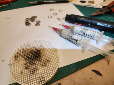
These are the tools you need: a ceramic soldering base, a pencil torch, and two types of silver solder - "hard" and "soft". The idea of two types of solder is that one melts at a much higher temperature, which allows you to make joints next to each other without the first one melting. You have to be strategic about which type of solder you are going to use. Ideally, the pieces should be clamped down because they have a tendency to suddenly shift when the solder melts, which will result in a discarded piece because once it is soldered on, there is no getting it off. Silver solder is STRONG!
I will describe what worked for me in case it helps other modellers who wish to do the same.
The rings were made by winding brass rod around a suitably shaped cylinder to create a spiral (I used wooden dowel that came with the kit). Then cut the spiral to make rings. Shape each ring with pliers, making sure that the two cut ends meet and will hold together by the springiness of the metal alone.
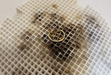
Lay your workpiece on the ceramic base. Here, the large ring has already been soldered, and I am soldering on the small rings. The silver solder comes as a paste, and it is very stiff when ejected from the syringe. It has a tendency to move the small rings when you try to apply it. I have found that it dissolves in Acetone and flows with heat. So after I lay out the workpiece with all the pieces I want to solder, I gently apply some heat and extrude some paste and gently touch the metal. This causes the flux to melt and flow into the gap without moving the piece. After all the paste has been extruded, apply aggressive heat with the pencil torch - you will see the flux start to bubble, the metal will glow red, then suddenly you get a flash of silver as the solder melts and cements the piece together. Immediately stop applying heat and move on to the next joint.
Once all the decorations have been made, you will note that the heating process discolours the metal. I lightly sand it and then give it an Acetone bath to remove any finger oil or excess flux. Then spray it with primer (I used Tamiya metal primer), then paint it to your liking.
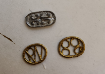
This is a comparison of the decoration supplied by Euromodel, and my scratchbuilt effort. These decorations are like my windows - they are inconsistent!
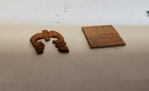
Once those were done, I moved on to carving the decorations for the topmost rail. This was done with a Dremel with and engraving tool, and a sharp hobby knife. To ensure that the pieces wouldn't break apart, I glued two planks at right angles to each other to make my own "plywood".
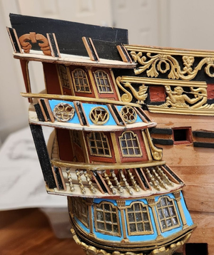
Once those decorations have been made, I mounted it on the ship. I decided to use the stanchions provided by the kit. This was after I bought some stanchions from RK Hobby (too wide), considered using toothpicks (also too wide), tried turning my own stanchions on a Dremel (takes too long, and too many breakages). Then I decided that Euromodel's stanchions don't look so bad after all. I am still undecided about it.
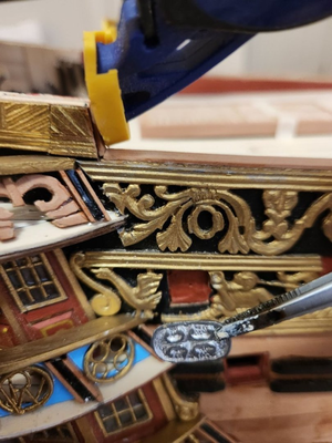
Another comparison of scratch-built vs. what was supplied in the kit. Other builders of this kit have drilled out the decorations so they don't look so coin-like, but then you lose the flexibility of sizing the decoration to the exact dimensions of your galleries. For my model, these were much too wide. They fit the railings provided by Euromodel, but those railings don't fit my galleries due to the modifications I made to the plans.
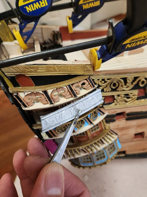
And this is a comparison of the upper galleries - carved vs. kit. You can see that the casting was quite poor with my kit and if I wanted to use it, I would have to re-scribe all the lines. You can also see that they are much too short for my galleries.
You can also see that I added a little door to access the top gallery. This is not indicated in the plans, but it seemed strange to have a beautifully built open air verandah with no way to access it. Placing a little hatch there makes it seem a little less abandoned.
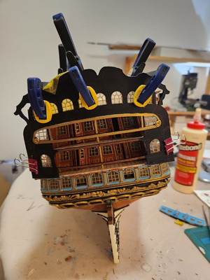
With all the galleries done, time to attach the transom fascia. I forgot to take a picture of all the reinforcements and gluing points I had added to make sure it stays on and doesn't fall off from the weight of all the metal parts. As I write this, I am waiting for the glue to dry. I used three types of glue - Titebond, epoxy, and CA. The purpose of the CA was to instantly secure the fascia once I had correctly positioned it (you can see my guide marks in the middle of the fascia). Masking tape protects some windows from the glue. You can also see that I have drawn the outlines of the decorations in pencil when I was debating whether to paint the transom fascia before or after mounting - I decided to paint after mounting. I will go back and secure the transom with pins for additional insurance.

These are the tools you need: a ceramic soldering base, a pencil torch, and two types of silver solder - "hard" and "soft". The idea of two types of solder is that one melts at a much higher temperature, which allows you to make joints next to each other without the first one melting. You have to be strategic about which type of solder you are going to use. Ideally, the pieces should be clamped down because they have a tendency to suddenly shift when the solder melts, which will result in a discarded piece because once it is soldered on, there is no getting it off. Silver solder is STRONG!
I will describe what worked for me in case it helps other modellers who wish to do the same.
The rings were made by winding brass rod around a suitably shaped cylinder to create a spiral (I used wooden dowel that came with the kit). Then cut the spiral to make rings. Shape each ring with pliers, making sure that the two cut ends meet and will hold together by the springiness of the metal alone.

Lay your workpiece on the ceramic base. Here, the large ring has already been soldered, and I am soldering on the small rings. The silver solder comes as a paste, and it is very stiff when ejected from the syringe. It has a tendency to move the small rings when you try to apply it. I have found that it dissolves in Acetone and flows with heat. So after I lay out the workpiece with all the pieces I want to solder, I gently apply some heat and extrude some paste and gently touch the metal. This causes the flux to melt and flow into the gap without moving the piece. After all the paste has been extruded, apply aggressive heat with the pencil torch - you will see the flux start to bubble, the metal will glow red, then suddenly you get a flash of silver as the solder melts and cements the piece together. Immediately stop applying heat and move on to the next joint.
Once all the decorations have been made, you will note that the heating process discolours the metal. I lightly sand it and then give it an Acetone bath to remove any finger oil or excess flux. Then spray it with primer (I used Tamiya metal primer), then paint it to your liking.

This is a comparison of the decoration supplied by Euromodel, and my scratchbuilt effort. These decorations are like my windows - they are inconsistent!

Once those were done, I moved on to carving the decorations for the topmost rail. This was done with a Dremel with and engraving tool, and a sharp hobby knife. To ensure that the pieces wouldn't break apart, I glued two planks at right angles to each other to make my own "plywood".

Once those decorations have been made, I mounted it on the ship. I decided to use the stanchions provided by the kit. This was after I bought some stanchions from RK Hobby (too wide), considered using toothpicks (also too wide), tried turning my own stanchions on a Dremel (takes too long, and too many breakages). Then I decided that Euromodel's stanchions don't look so bad after all. I am still undecided about it.

Another comparison of scratch-built vs. what was supplied in the kit. Other builders of this kit have drilled out the decorations so they don't look so coin-like, but then you lose the flexibility of sizing the decoration to the exact dimensions of your galleries. For my model, these were much too wide. They fit the railings provided by Euromodel, but those railings don't fit my galleries due to the modifications I made to the plans.

And this is a comparison of the upper galleries - carved vs. kit. You can see that the casting was quite poor with my kit and if I wanted to use it, I would have to re-scribe all the lines. You can also see that they are much too short for my galleries.
You can also see that I added a little door to access the top gallery. This is not indicated in the plans, but it seemed strange to have a beautifully built open air verandah with no way to access it. Placing a little hatch there makes it seem a little less abandoned.

With all the galleries done, time to attach the transom fascia. I forgot to take a picture of all the reinforcements and gluing points I had added to make sure it stays on and doesn't fall off from the weight of all the metal parts. As I write this, I am waiting for the glue to dry. I used three types of glue - Titebond, epoxy, and CA. The purpose of the CA was to instantly secure the fascia once I had correctly positioned it (you can see my guide marks in the middle of the fascia). Masking tape protects some windows from the glue. You can also see that I have drawn the outlines of the decorations in pencil when I was debating whether to paint the transom fascia before or after mounting - I decided to paint after mounting. I will go back and secure the transom with pins for additional insurance.
- Joined
- Apr 11, 2015
- Messages
- 92
- Points
- 103

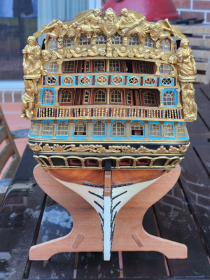
A milestone has been reached ... I have completed the transom. In case you are wondering why my colour scheme deviates from other RW's, I was guided by John Clevely's painting of HMS Royal George from 1756:
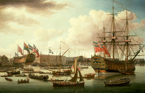
I did consider painting the entire fascia blue as per that painting, and went as far as creating a mock-up. But I decided that the supplied castings would not provide enough coverage, and there would be large areas of flat colour. Other RW's on MSW have the transoms painted black, or left natural wood - I studied those images closely. Black made the most sense, because it matched the strip going down the side. Going all gold might be a bit excessive, but all gold camouflages flat areas pretty well. In the end:
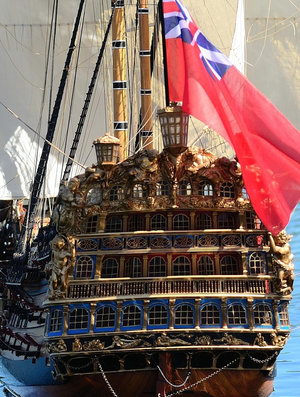
... this is a photo of the stern of Victor Yankovich's Royal William, which looks to be better than museum quality. I know it is foolish to post this picture so that you can directly compare his sheer modelling perfection to my hack job, but this colour scheme looked right to me. He went all gold. So that's what I chose.
Before I purchased the ship, I had already inspected a friend's RW kit and decided that I would scratch-build the transom. Everything that you see except for the cast metal decorations and pre-cut transom fascia has been scratch built ... which is why it looks so wonky.
I am not happy with how I applied the stanchions, they are uneven and look like they need a visit to a good dentist. I will tear out some of them and replace them so that they are more straight.
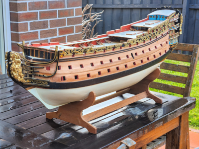
It was a typical Melbourne day (raining one moment, sunny the next). So once the rain stopped, I took the ship outside for some photos. I never did like the look of the gold decorations on the front bulkhead, so I painted them all black.
- Joined
- Apr 11, 2015
- Messages
- 92
- Points
- 103

From here on, I am on to the "easy" part of the build, where I am adding details and not structural elements. Anything I do from here can be rectified if I make a mistake. In a sense, this is much more relaxing than having to measure and triple measure parts which have not been created yet or attempt to visualize how something that can not be supported is going to fit. I have made everything fit through my own solution - by scratchbuilding parts so I can guarantee that they fit.
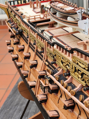
I have completed all the gun carriages now. What started off as fun when I did the first one quickly became tedious after having to do so many. Fortunately, I made a gun carriage rigging jig that made my life easier:
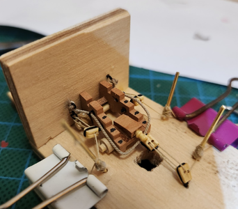
It is just a simple jig I threw together from spare kit plywood with holes drilled in it. You can see the features of the jig: there is a square hole that allows me to work on that block from the bottom. I made all the ring bolts oversized so I just push the bolt through the hole, bend the wire at the back, and it holds it secure while I pull on the ropes. There are also brass rods which allow me to make rope coils.
You can see that I am using my own scratch built gun carriages instead of the supplied kit carriages which are too square and do not have the tapering angles found on real gun carriages.
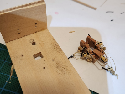
Once rigging is finished, simply pull all the ringbolts out of the holes and it is ready for mounting on the ship.
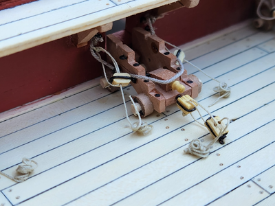
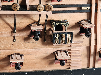
Here is one of them, mounted on the ship. I had 30 of these to make, I estimate it took me 2 hours per gun carriage. 3-4 hours to mill all the parts, another 4-5 hours to make all the ringbolts and tackle, 30 min per carriage to assemble, 45 min per carriage to rig, and 10 min per carriage to mount. Then there are the guns which took me a few hours to clean and blacken. I will wait until more of the hull is completed before I mount the guns.
It took a lot longer than 10 minutes for tricky carriages like this one which are under the gangway. I rehearsed talking like a sailor when attempting to push pins into holes that I could barely see. I don't know what I was thinking when I installed the gangway before making the carriages - so other RW builders, don't do this!
For historic accuracy I should have painted the carriages red. But I do like the look of pear, so I left them in natural wood.
I was not happy with the appearance of the belfry as supplied with the RW kit. It appears to be taken from the model of the RW at the National Maritime Museum in Greenwich, UK. This is a photo of the belfry that I took when I visited Greenwich a few years ago:
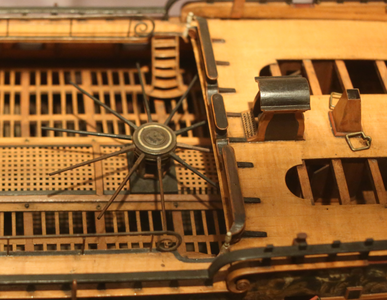
However, the model at the USNA museum is much more ornate:
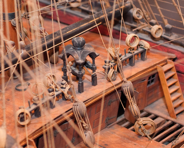
So, I pondered how I am going to replicate that, given that carving it is beyond my skill level. I came up with this solution ... I don't know if I have invented a new modelling technique.
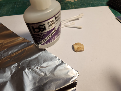
What you need is some tinfoil, CA glue, and a mold to form the shape around. My idea was to laminate multiple sheets of foil with CA glue around the mold. The mold was made by taking a dowel, splitting it in half, and then carving out the underside of one of the dowels so that the other half could fit. A Dremel with a drum sander makes easy work of it.
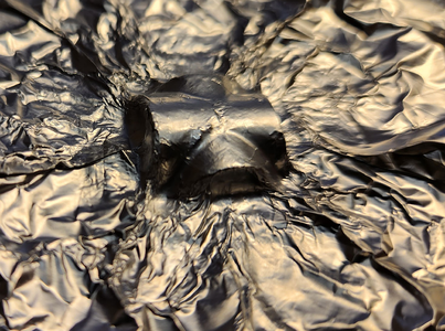
Rub the mold liberally with vaseline (in case the foil tears and CA sticks the foil to the mold!). Then lay the first layer of foil on top and gently work around the curves with a Q-tip cotton bud. Once nicely pressed, apply a liberal layer of CA glue. It needs to be slow curing!
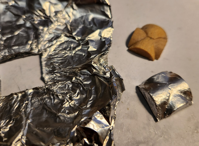
I did 7 layers of tinfoil, then left it alone for a couple of hours to make sure the CA glue really sets. Cut it out and Dremel it into shape. At this point, it is what you expect 7 layers of laminated alfoil to be - it is really light, but stiff enough to handle. But it is not super tough and it WILL deform if you do not handle it delicately. But ... it's a belfry. It is not a structural component (where strength is important), and I do not anticipate anybody is going to touch it. So it will do.
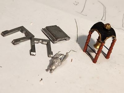
After I sprayed it with metal primer, I painted it. This is the result, compared to the Euromodel supplied belfry.
I purchased the bell from a model shop. It is turned brass and much nicer than the cast white metal bell supplied with the kit.
I have completed all the gun carriages now. What started off as fun when I did the first one quickly became tedious after having to do so many. Fortunately, I made a gun carriage rigging jig that made my life easier:

It is just a simple jig I threw together from spare kit plywood with holes drilled in it. You can see the features of the jig: there is a square hole that allows me to work on that block from the bottom. I made all the ring bolts oversized so I just push the bolt through the hole, bend the wire at the back, and it holds it secure while I pull on the ropes. There are also brass rods which allow me to make rope coils.
You can see that I am using my own scratch built gun carriages instead of the supplied kit carriages which are too square and do not have the tapering angles found on real gun carriages.

Once rigging is finished, simply pull all the ringbolts out of the holes and it is ready for mounting on the ship.

Here is one of them, mounted on the ship. I had 30 of these to make, I estimate it took me 2 hours per gun carriage. 3-4 hours to mill all the parts, another 4-5 hours to make all the ringbolts and tackle, 30 min per carriage to assemble, 45 min per carriage to rig, and 10 min per carriage to mount. Then there are the guns which took me a few hours to clean and blacken. I will wait until more of the hull is completed before I mount the guns.
It took a lot longer than 10 minutes for tricky carriages like this one which are under the gangway. I rehearsed talking like a sailor when attempting to push pins into holes that I could barely see. I don't know what I was thinking when I installed the gangway before making the carriages - so other RW builders, don't do this!
For historic accuracy I should have painted the carriages red. But I do like the look of pear, so I left them in natural wood.
I was not happy with the appearance of the belfry as supplied with the RW kit. It appears to be taken from the model of the RW at the National Maritime Museum in Greenwich, UK. This is a photo of the belfry that I took when I visited Greenwich a few years ago:

However, the model at the USNA museum is much more ornate:

So, I pondered how I am going to replicate that, given that carving it is beyond my skill level. I came up with this solution ... I don't know if I have invented a new modelling technique.

What you need is some tinfoil, CA glue, and a mold to form the shape around. My idea was to laminate multiple sheets of foil with CA glue around the mold. The mold was made by taking a dowel, splitting it in half, and then carving out the underside of one of the dowels so that the other half could fit. A Dremel with a drum sander makes easy work of it.

Rub the mold liberally with vaseline (in case the foil tears and CA sticks the foil to the mold!). Then lay the first layer of foil on top and gently work around the curves with a Q-tip cotton bud. Once nicely pressed, apply a liberal layer of CA glue. It needs to be slow curing!

I did 7 layers of tinfoil, then left it alone for a couple of hours to make sure the CA glue really sets. Cut it out and Dremel it into shape. At this point, it is what you expect 7 layers of laminated alfoil to be - it is really light, but stiff enough to handle. But it is not super tough and it WILL deform if you do not handle it delicately. But ... it's a belfry. It is not a structural component (where strength is important), and I do not anticipate anybody is going to touch it. So it will do.

After I sprayed it with metal primer, I painted it. This is the result, compared to the Euromodel supplied belfry.
I purchased the bell from a model shop. It is turned brass and much nicer than the cast white metal bell supplied with the kit.
- Joined
- Apr 11, 2015
- Messages
- 92
- Points
- 103

Many years ago, my friend passed away. He was only 41 years old. I was actually working on this ship when I received a phone call to tell me the terrible news. I painted a tribute to Daniel on one of the bulkheads:
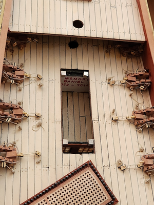
Over the years, the partially completed ship has been on display in my living room and I see that memorial every time I looked at the ship. I could not bear to cover it up forever, so I installed some magnets - those silver things on each corner of the hole. This way I can remove the grate and look at the memorial.
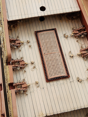
Once the grate is installed, you would never suspect that it could be removed to reveal a hidden message inside.
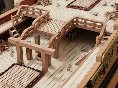
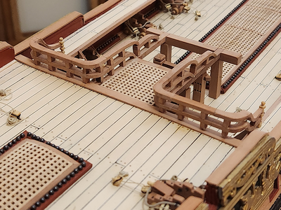
The quarterdeck railings were devilishly difficult to make. The railings alone contain 40 parts (not counting the stanchions, of which there are 34). Of those 40 parts, 12 hard to be carved because it is simply not possible to bend wood like that. You will notice that I included the Newell posts (the turned stanchions at the ends of the railings at the top of the staircase). These were turned from a toothpick on a Dremel. I used needle files to shape them.
The mast collar was made on my lathe. I don't know if Euromodel provided mast collars, I searched around in my parts and couldn't find any. So I made them.
You will also notice that the gratings have a subtle curve. The cannonball channel was made on my Proxxon mill and IT TOOK FOREVER. The first problem was figuring out how to hold the workpiece down. I made a custom jig out of some spare plywood by using the mill to draw a straight line, then I glued two pieces of wood using the straight line as a guide. Then I used the mill again to square up the faces to make sure they were 100% parallel. A couple of self tapping screws held the workpiece down while I milled out the holes for the cannonballs. In the end I managed to get an excellent result.

Over the years, the partially completed ship has been on display in my living room and I see that memorial every time I looked at the ship. I could not bear to cover it up forever, so I installed some magnets - those silver things on each corner of the hole. This way I can remove the grate and look at the memorial.

Once the grate is installed, you would never suspect that it could be removed to reveal a hidden message inside.


The quarterdeck railings were devilishly difficult to make. The railings alone contain 40 parts (not counting the stanchions, of which there are 34). Of those 40 parts, 12 hard to be carved because it is simply not possible to bend wood like that. You will notice that I included the Newell posts (the turned stanchions at the ends of the railings at the top of the staircase). These were turned from a toothpick on a Dremel. I used needle files to shape them.
The mast collar was made on my lathe. I don't know if Euromodel provided mast collars, I searched around in my parts and couldn't find any. So I made them.
You will also notice that the gratings have a subtle curve. The cannonball channel was made on my Proxxon mill and IT TOOK FOREVER. The first problem was figuring out how to hold the workpiece down. I made a custom jig out of some spare plywood by using the mill to draw a straight line, then I glued two pieces of wood using the straight line as a guide. Then I used the mill again to square up the faces to make sure they were 100% parallel. A couple of self tapping screws held the workpiece down while I milled out the holes for the cannonballs. In the end I managed to get an excellent result.
- Joined
- Apr 11, 2015
- Messages
- 92
- Points
- 103

Next up is the poop deck rail. According to the plans this was elaborately decorated. Euromodel does not include this part in their kit, so I fabricated my own by carving it. I again used the same method of creating my own plywood out of laminated pear strips for strength and so that it won't fracture when I am carving the tiny fragile bits. Here is my laminated strip cut down to size with the lines marked with the aid of a pencil and a compass:
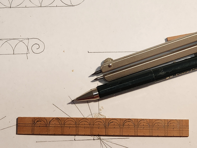
And here is the completed deck rail compared to the plans:
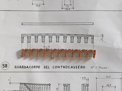
I used a tiny bit of creative license and made them close to what the plans suggested but not quite. Regardless, it looks beautiful on the ship.
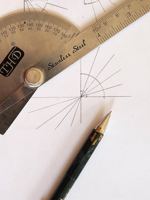
I also tackled the dreaded curved staircase. This is my method: first, calculate the angle required for the steps then draw it out on a piece of paper. I wanted 6 steps, so 90/5 = 18 degrees. These were accurately drawn out with a protractor:
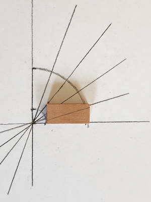
The first step is laid, and with the line for the next step is carefully marked out. Glue the next step up to the line, taking care to align the inside of the step with the inside curve.
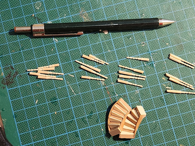
As the steps go up, it becomes more and more difficult to support the steps without them toppling over. I simply used more step offcuts to support the steps with the bottom step glued to the template to stop it from moving. Don't worry, once it's done just rip it off the paper and sand off the glue. It won't matter if it's ugly because it is on the bottom and won't be seen. Here are both steps complete:
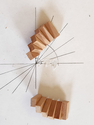
Now both steps can have stringers attached. I decided to add some holly planks to match the other steps. I turned 12 toothpicks for stanchions.
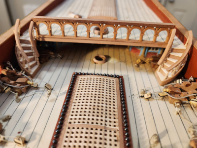
And here is everything attached on the ship:

And here is the completed deck rail compared to the plans:

I used a tiny bit of creative license and made them close to what the plans suggested but not quite. Regardless, it looks beautiful on the ship.
I also tackled the dreaded curved staircase. This is my method: first, calculate the angle required for the steps then draw it out on a piece of paper. I wanted 6 steps, so 90/5 = 18 degrees. These were accurately drawn out with a protractor:

The first step is laid, and with the line for the next step is carefully marked out. Glue the next step up to the line, taking care to align the inside of the step with the inside curve.

As the steps go up, it becomes more and more difficult to support the steps without them toppling over. I simply used more step offcuts to support the steps with the bottom step glued to the template to stop it from moving. Don't worry, once it's done just rip it off the paper and sand off the glue. It won't matter if it's ugly because it is on the bottom and won't be seen. Here are both steps complete:

Now both steps can have stringers attached. I decided to add some holly planks to match the other steps. I turned 12 toothpicks for stanchions.

And here is everything attached on the ship:

- Joined
- Apr 11, 2015
- Messages
- 92
- Points
- 103

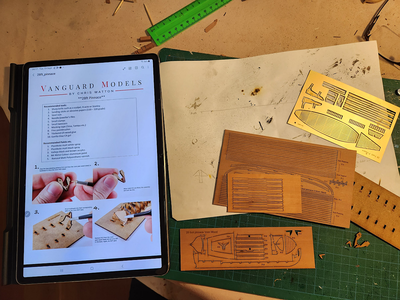
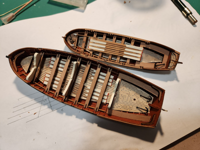
I received something rather nice in the mail - a pair of ships boats from Vanguard Models. Chris Watton has a reputation as one of the best model ship designers in the world, and no wonder. These little marvels ticked all the boxes - reasonably priced, nice wood (pear), superb instructions, precisely cut parts, extra wood and spare parts in case you make mistakes and drop parts on the floor (where you will never find them again, these are TINY!), and fun to build. I honestly can not think of a way these little boat kits can be improved.
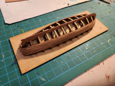
Here is the one of the boats coming together:
And both boats completed:
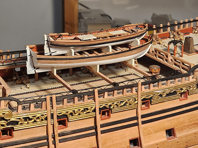
And both boats mounted on the ship:
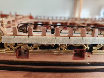
The sharp eyed among you will notice the elaborate safety rail on the gangway. These were painstakingly soldered from brass wire and is more elaborate than depicted on any reference I can find. Those half circles really help with rigidity.
I did not take any shots of the gangway rail under construction, but you can see some of it here. I am installing the outer rails. I decided to taper the stanchions as per the plans, 3mm in the base to 2mm at the top. What you need is a tilting table for your Byrnes Table Saw. I have one, but it is a complete pain to use because it is impossible to set up precisely. I had to estimate the angle, make a test cut, measure the angle, and repeat until I had the result that I wanted. Once enough stock for all the stanchions has been milled, individual stanchions can be cut out.
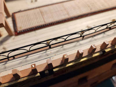
Each alternate stanchion was pinned to the ship. Given that I have no training in engineering, I have a somewhat Victorian attitude to building. I over-engineer everything and make it as solid as possible.

Here is the one of the boats coming together:

And both boats completed:

And both boats mounted on the ship:

The sharp eyed among you will notice the elaborate safety rail on the gangway. These were painstakingly soldered from brass wire and is more elaborate than depicted on any reference I can find. Those half circles really help with rigidity.

I did not take any shots of the gangway rail under construction, but you can see some of it here. I am installing the outer rails. I decided to taper the stanchions as per the plans, 3mm in the base to 2mm at the top. What you need is a tilting table for your Byrnes Table Saw. I have one, but it is a complete pain to use because it is impossible to set up precisely. I had to estimate the angle, make a test cut, measure the angle, and repeat until I had the result that I wanted. Once enough stock for all the stanchions has been milled, individual stanchions can be cut out.

Each alternate stanchion was pinned to the ship. Given that I have no training in engineering, I have a somewhat Victorian attitude to building. I over-engineer everything and make it as solid as possible.
- Joined
- Apr 11, 2015
- Messages
- 92
- Points
- 103

Now I tackled an area which has been of great concern to me since I started this project - the lanterns. Euromodel supplies the lanterns as a solid cast metal part with metal plates for the windows. If you look over all the other RW build logs, every other modeller has elected to paint the windows. I thought this would look out of place in my model, since I had fabricated all the windows so that they are clear and can be backlit. I wanted the lanterns to light up, so I ordered the largest lanterns from Vanguard Models:
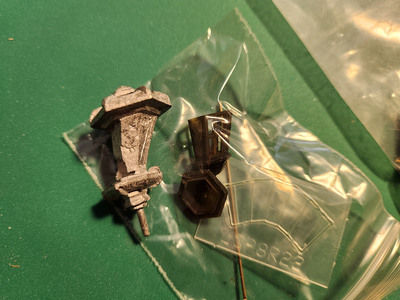
They are little jewels compared to the poorly cast Euromodel part. But sadly, they were too small and I can't use them. So I had to come up with my own solution.
Sadly I did not take photos of the complete process, so you will have to rely on my description of what I did. The solution was to cut off the top and bottom of the Euromodel lantern, and fabricate everything else in between.
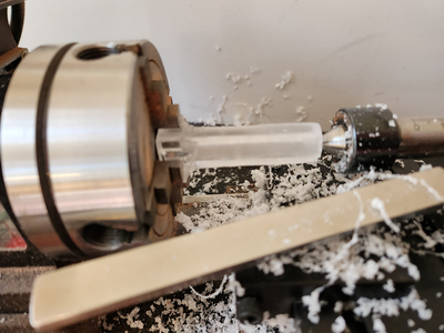
The central support would be an acrylic tube which had to be machined to size. Since I did not have any acrylic tube, I had to make my own. I did this by THOROUGHLY CA'ing sheets of acrylic together and then machining it on my lathe. This is an incredibly messy process and the tube becomes really fragile just as it starts to reach the proper dimension. I needed 3 tubes for 3 lanterns, I had 5 failures - all fractured just as I was about to reach my goal.
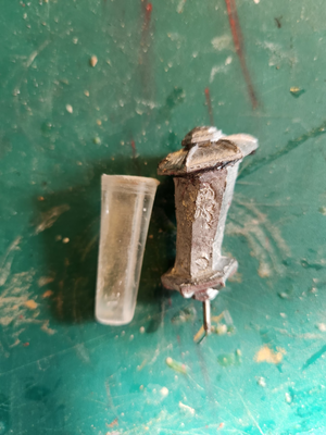
Here is a completed tube next to the Euromodel lantern. I copied the dimensions of the cast central support exactly but did not bother copying the squared off facets because I would not be using the lantern face plates supplied by Euromodel.
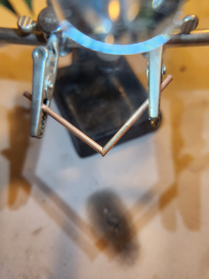
Next problem was the lantern support. It had to be hollow so that the wiring of the LED's can pass through it. I tried bending the tube, but it crimped at the bend and the wires could not pass. The solution was to cut to copper tube (2mm diam) to 45 deg and solder them together. I did not take photos of the completed joint, but after the solder went on I reinforced it with epoxy to make it extra rigid.
I then passed the copper tube through the base of the lantern, glued the acrylic tube on, and then the top tube. These were held with a mixture of CA and epoxy (CA to hold the part in place while waiting for the epoxy to set). To increase the strength of the joint, little holes were drilled into the top and bottom metal plates to give the epoxy something to grip. Once cured, the whole assembly was pleasingly solid.
I then fabricated the lantern faces out of acetate sheets and detailed with painted styrene. I did consider drilling out the windows on the kit plates, but it was just as fast to make my own parts given the sheer annoyance of trying to drill through white metal. It melts, refuses to be worked on, and breaks drill bits. The other advantage of not using the kit parts is that I can get a far more precise fit by making my own parts.
Once done and painted, I mounted the lanterns on the model and anxiously tested to see if it would work:
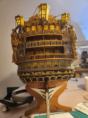
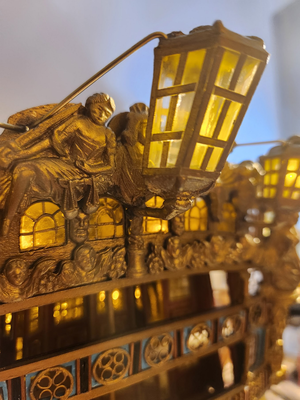
IT DOES!
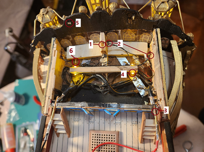
The poop cabin is a busy place with a number of features crammed into the tiny space. All the wires had to be routed away from the lights so that they can not be seen.
1: Hole for flag staff support.
2. Tiny wire going to the lanterns. You can see that the middle lantern is awfully close to the hole for the flag staff. You can also see how far the side lantern supports protrude into the hull. Not only are they epoxied in place, the ends of the tubes are bent so that they won't slip out of the hull.
3. Copper tube with brass rods so that I can power the lights. When the ship is complete, the lights will be powered through the stand. You may recall from much earlier posts when I was constructing the skeleton that I had soldered cable into some nuts and mounted it into the keel, so that when the model is screwed into the base, it will receive electricity that way. In the meantime, this is a subtle solution which is hidden behind the staircases and the copper tubes can barely be seen.
4. LED's for lighting the poop deck.
5. Brass wire terminating in the transom fascia. These are MUCH thicker than suggested by Euromodel, but once they were installed the lanterns were solid. You can pick the ship up by the lanterns, they are that securely mounted.
6. Pins for mounting the transom fascia. These are two of the 10 pins I installed. Yes, the transom isn't going to fall off.
In fact the whole thing is so secure that the model can be lifted off the base with the lanterns.

They are little jewels compared to the poorly cast Euromodel part. But sadly, they were too small and I can't use them. So I had to come up with my own solution.
Sadly I did not take photos of the complete process, so you will have to rely on my description of what I did. The solution was to cut off the top and bottom of the Euromodel lantern, and fabricate everything else in between.

The central support would be an acrylic tube which had to be machined to size. Since I did not have any acrylic tube, I had to make my own. I did this by THOROUGHLY CA'ing sheets of acrylic together and then machining it on my lathe. This is an incredibly messy process and the tube becomes really fragile just as it starts to reach the proper dimension. I needed 3 tubes for 3 lanterns, I had 5 failures - all fractured just as I was about to reach my goal.

Here is a completed tube next to the Euromodel lantern. I copied the dimensions of the cast central support exactly but did not bother copying the squared off facets because I would not be using the lantern face plates supplied by Euromodel.

Next problem was the lantern support. It had to be hollow so that the wiring of the LED's can pass through it. I tried bending the tube, but it crimped at the bend and the wires could not pass. The solution was to cut to copper tube (2mm diam) to 45 deg and solder them together. I did not take photos of the completed joint, but after the solder went on I reinforced it with epoxy to make it extra rigid.
I then passed the copper tube through the base of the lantern, glued the acrylic tube on, and then the top tube. These were held with a mixture of CA and epoxy (CA to hold the part in place while waiting for the epoxy to set). To increase the strength of the joint, little holes were drilled into the top and bottom metal plates to give the epoxy something to grip. Once cured, the whole assembly was pleasingly solid.
I then fabricated the lantern faces out of acetate sheets and detailed with painted styrene. I did consider drilling out the windows on the kit plates, but it was just as fast to make my own parts given the sheer annoyance of trying to drill through white metal. It melts, refuses to be worked on, and breaks drill bits. The other advantage of not using the kit parts is that I can get a far more precise fit by making my own parts.
Once done and painted, I mounted the lanterns on the model and anxiously tested to see if it would work:


IT DOES!

The poop cabin is a busy place with a number of features crammed into the tiny space. All the wires had to be routed away from the lights so that they can not be seen.
1: Hole for flag staff support.
2. Tiny wire going to the lanterns. You can see that the middle lantern is awfully close to the hole for the flag staff. You can also see how far the side lantern supports protrude into the hull. Not only are they epoxied in place, the ends of the tubes are bent so that they won't slip out of the hull.
3. Copper tube with brass rods so that I can power the lights. When the ship is complete, the lights will be powered through the stand. You may recall from much earlier posts when I was constructing the skeleton that I had soldered cable into some nuts and mounted it into the keel, so that when the model is screwed into the base, it will receive electricity that way. In the meantime, this is a subtle solution which is hidden behind the staircases and the copper tubes can barely be seen.
4. LED's for lighting the poop deck.
5. Brass wire terminating in the transom fascia. These are MUCH thicker than suggested by Euromodel, but once they were installed the lanterns were solid. You can pick the ship up by the lanterns, they are that securely mounted.
6. Pins for mounting the transom fascia. These are two of the 10 pins I installed. Yes, the transom isn't going to fall off.
In fact the whole thing is so secure that the model can be lifted off the base with the lanterns.
- Joined
- Apr 11, 2015
- Messages
- 92
- Points
- 103

On the 6th of October, I reached another milestone. The hull had been finished, and I was ready to move on to masts and rigging. Here are a few more photos showing some features on the model.
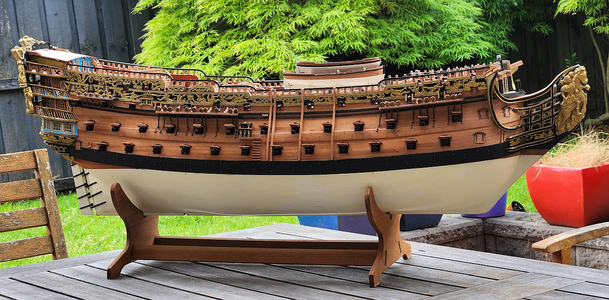
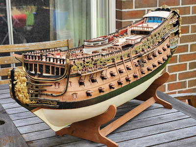
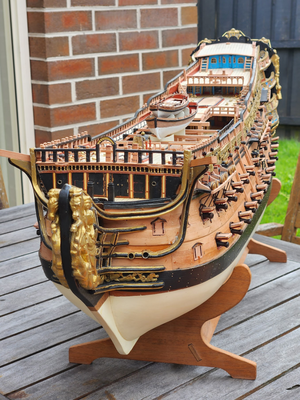
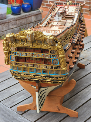
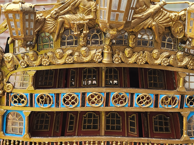
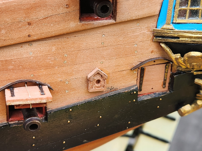
Entry way. As per usual, I did not use the kit parts. The railing was made by coiling some fine brass wire around a jig, then flattening it in a vice, then painted. The columns were made by wrapping the same fine wire around a brass rod and painted. The roof was the kit part. Note the taper on the underside of the steps, this was quite troublesome to make. I milled out a "V" groove on my Proxxon MF70 and then sawed it in half. Then each step was shaped with a Dremel.
The shroud stays reach down to the wales. The bottom stay has eyes for nails - these were too large (as noted in other build logs), but instead of replacing them I flattened them with some pliers. They were also pickled in some blackening solution because I did not like the shiny brass - it called too much attention to itself. The angle of the stays was set with a string tied to a dummy mast.
The rigols were made from brass sheet and blackened. I could not find brass strip of the correct size and thickness, so each rigol had to be individually cut out of the sheet. The cutting process leaves them curled, so they had to be flattened in a vice. I found that the cap of a Vallejo paint container has the perfect curvature to form the rigols.
Here is a carved chesstree. My carving skills are quite rudimentary and I was unable to obtain the finish that I wanted. Still, the part and the imperfections are small enough that hopefully they won't be noticed. The gun hinges were from Rick Shousha at the Modeller's Workshop, who made a limited run of RW gunport hinges. They are too short, but preferable to the overly thick kit supplied parts.
Roughtree block. It has all the features indicated in the Euromodel plans, but it has been slightly restyled.
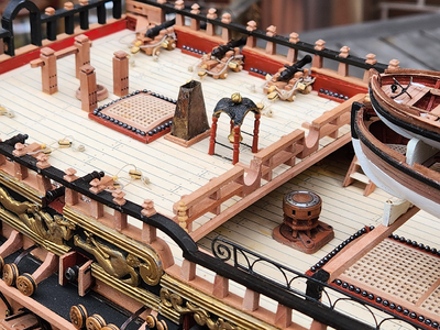
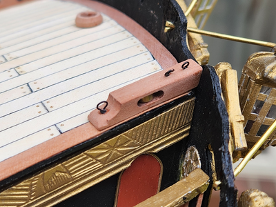
I realized I haven't posted a clear shot of the fo'c'sle deck so here it is. Note the fo'c'sle deck railing which deviates from Euromodel's plans. My research suggested that the beam supports should be round. Indeed this was depicted in the RW in the NMM in Greenwich. So I rounded the bottom and made them thick and sturdy.


Entry way. As per usual, I did not use the kit parts. The railing was made by coiling some fine brass wire around a jig, then flattening it in a vice, then painted. The columns were made by wrapping the same fine wire around a brass rod and painted. The roof was the kit part. Note the taper on the underside of the steps, this was quite troublesome to make. I milled out a "V" groove on my Proxxon MF70 and then sawed it in half. Then each step was shaped with a Dremel.

The shroud stays reach down to the wales. The bottom stay has eyes for nails - these were too large (as noted in other build logs), but instead of replacing them I flattened them with some pliers. They were also pickled in some blackening solution because I did not like the shiny brass - it called too much attention to itself. The angle of the stays was set with a string tied to a dummy mast.
The rigols were made from brass sheet and blackened. I could not find brass strip of the correct size and thickness, so each rigol had to be individually cut out of the sheet. The cutting process leaves them curled, so they had to be flattened in a vice. I found that the cap of a Vallejo paint container has the perfect curvature to form the rigols.

Here is a carved chesstree. My carving skills are quite rudimentary and I was unable to obtain the finish that I wanted. Still, the part and the imperfections are small enough that hopefully they won't be noticed. The gun hinges were from Rick Shousha at the Modeller's Workshop, who made a limited run of RW gunport hinges. They are too short, but preferable to the overly thick kit supplied parts.

Roughtree block. It has all the features indicated in the Euromodel plans, but it has been slightly restyled.

I realized I haven't posted a clear shot of the fo'c'sle deck so here it is. Note the fo'c'sle deck railing which deviates from Euromodel's plans. My research suggested that the beam supports should be round. Indeed this was depicted in the RW in the NMM in Greenwich. So I rounded the bottom and made them thick and sturdy.
- Joined
- Apr 11, 2015
- Messages
- 92
- Points
- 103

And that was my last post on the other forum, which brings us up to date. I don't think I am going to post on that other forum very much now. I am pissed off that all my friends have disappeared from bannings even though I haven't been banned from there myself.
Right now the project is partially stalled because I am unable to start rigging because I do not have enough rope. I am waiting for the rope to arrive from the USA. They estimated 20 days shipping time, so I have nothing left to do until the end of the month. In the meantime, I will work on spars, a custom plinth, and anything that does not require rope.
Right now the project is partially stalled because I am unable to start rigging because I do not have enough rope. I am waiting for the rope to arrive from the USA. They estimated 20 days shipping time, so I have nothing left to do until the end of the month. In the meantime, I will work on spars, a custom plinth, and anything that does not require rope.
Hi Keith,
A wonderfull blog and even more beautiful ship.
RW is still a fantastic ship to build. PS Victor is also a member here.
A wonderfull blog and even more beautiful ship.
RW is still a fantastic ship to build. PS Victor is also a member here.
Beautiful executed works on this kit model. Great bashing!
Many thanks for sharing it with us.
Many thanks for sharing it with us.


