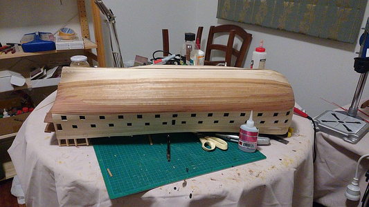
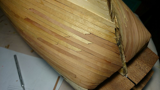
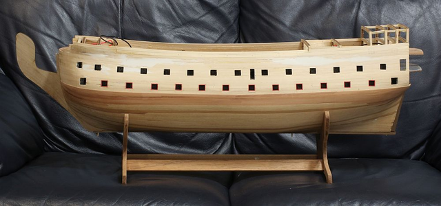
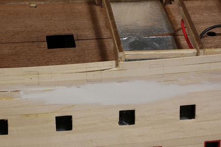
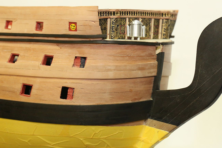
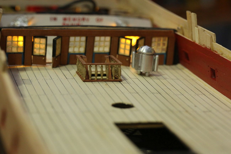
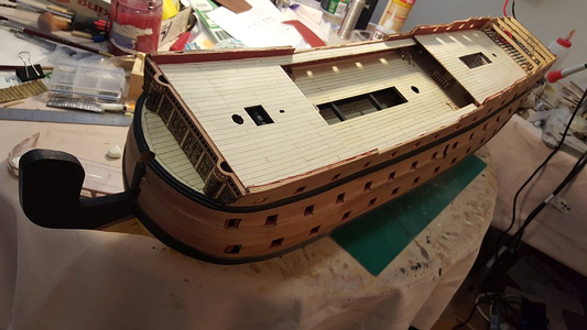
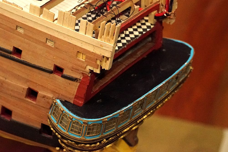
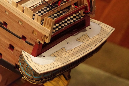
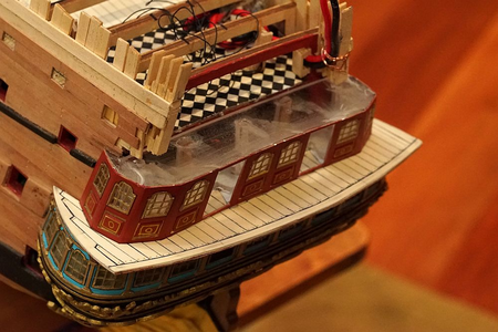
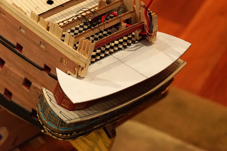
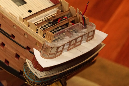
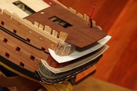
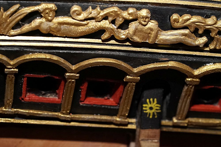
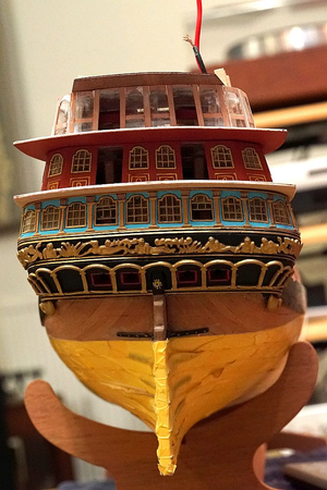
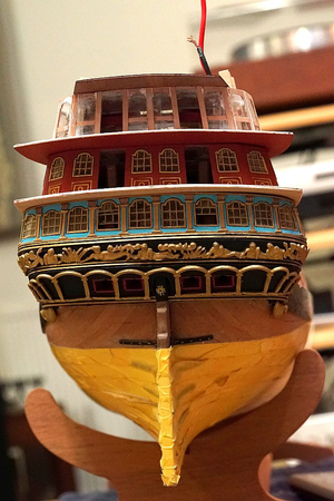
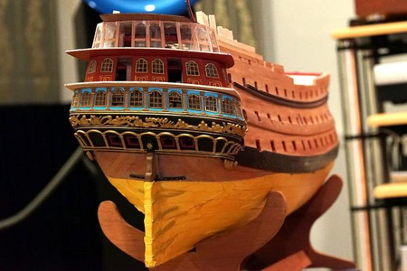
HMS Royal William 1719, Euromodel, 1:72

Joined
Apr 11, 2015
Messages
92
Points
103

Hello everyone, I signed up on this forum many years ago but did not visit it much. I took a break from ship modelling, and over the years, the forum which I used to frequent appears to be a ghost town with many of its members migrated here. So I thought that I would migrate my build log to this forum. Please be patient as I rebuild this build log, it will take me quite a while because I started on this kit in 2014 (!!!) and have been working on it intermittently ever since.

From Wikipedia: "HMS Prince was rebuilt by Robert Lee at Chatham Dockyard in 1692, and renamed at the same time as HMS Royal William. During the War of the Grand Alliance the ship saw action at the Battle of Barfleur of 19 May 1692.[5] Prince belonged to the red squadron and carried the flag of Rear-admiral of the red Sir Cloudesley Shovell. She was the first ship to break the French line during the battle.

Later she was rebuilt for a second time by John Naish of Portsmouth but using Chatham Dockyard from 1714, relaunching on 3 September 1719. She was laid up after her re-launch and saw no service at all until she was reduced to an 84-gun Second rate ship in 1756"
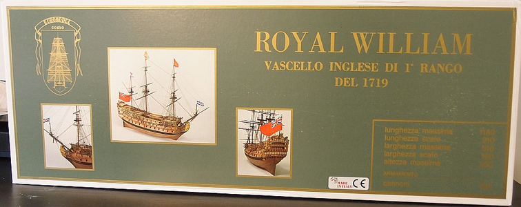
1697520009274.png

The box is really large and heavy, and arrives absolutely packed. Every bit of spare space is taken up by ... peanut foam. I filled up a plastic bag full of these annoying things and was able to get at the kit.

First, the bad:
1697520057189.png

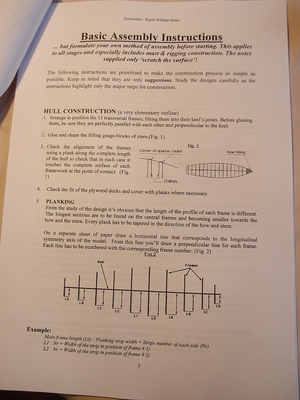
The instructions are not very good (to say the least). For a kit of this complexity, the rather thin instruction booklet only contains THREE pages of instructions, of which the first page is taken up by the history of the ship, and some congratulatory notes. This shot is of the second page, and contains nothing that no experienced modeller wouldn't know. OTOH the plans (see next post) are excellent, however many diagrams in the plans could have been printed on smaller pieces of paper and bound in a booklet instead.
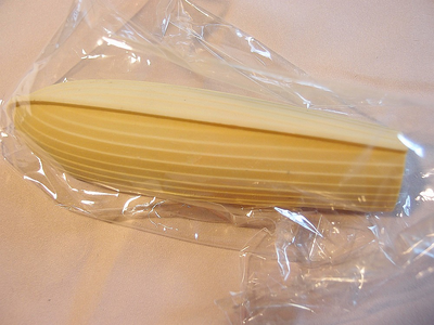
1697520072270.png

The ships boat is a cast resin item. Whilst it is well cast, other kit manufacturers are offering plank-on-frame boats. Oh yes, only one boat? For a first rate ship?
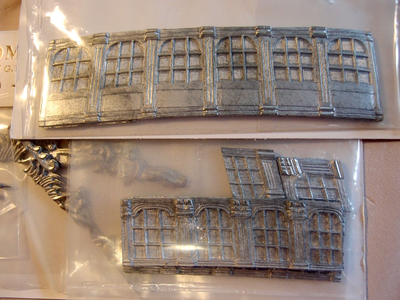
1697520119856.png

Some of the castings are not very good. Look at how chunky this window is. These will have to go into the bin.
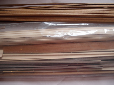
1697520181404.png

However, the wood is of decent quality. On some older RW kits, the masts are pre-tapered. On this brand new RW kit, fresh from Italy, the masts are not. I ended up replacing most of the wood with pear and holly that I ordered from Hobbymill before they closed.
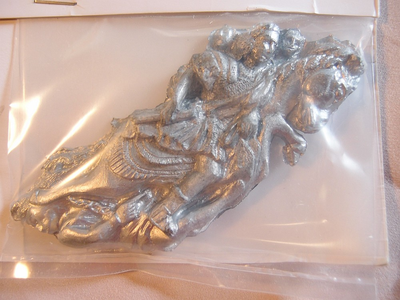
1697520244672.png

Some other castings, like the figurehead, are excellent.
1697520322075.png

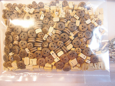
The blocks are probably the best I have ever seen included in a model kit.
 
1697520382574.png

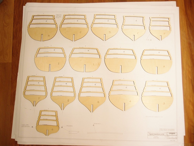
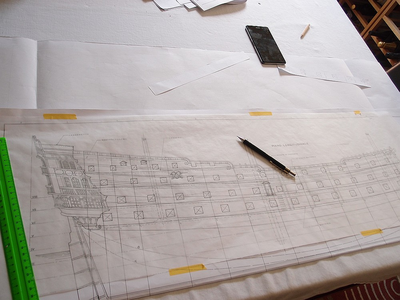
I laid out all the frames against the plans. In particular, I was looking for the incorrectly labelled bulkheads E and F as noted by other builders. Sure enough, as he described, on Plan Sheet 4 the drawing shows correct placement of the bulkheads, but the labels for E and F are the wrong way round. Importantly, the bulkheads themselves are correctly labelled.

As noted elsewhere, the RW bulkheads are named according to ship builders convention, as follows:

(STERN) 8 - 7 - 6 - 5 - 4 - 3 - 2 - 1 - 0 - A - B - C - D - E - F (BOW)

1697520455178.png
1697520468872.png

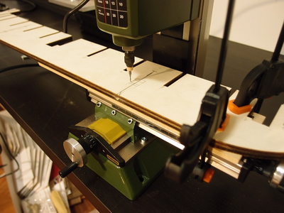
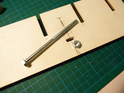
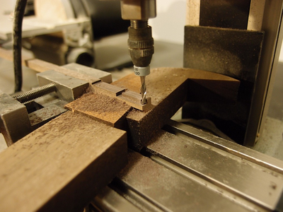
The next thing is to drill the holes in the false keel for future attachment of a stand. I drilled a 6mm diameter hole in the 10mm width false keel - only 2mm of clearance either side! The precision of the drill press ensured that my hole was perfectly centered. The above pictures show me milling a hole to accept the nut. Not pictured are the cheeks that I made to strengthen the weakened keel and to hold the nut in.

1697520544952.png

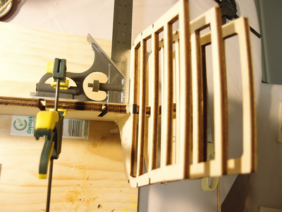
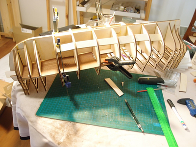
Start of bulkhead attachment. The bulkheads were attached with the aid of a square to ensure ... squareness. As noted elsewhere, the bulkheads are a rather sloppy fit and need to be shimmed.

1697520581973.png

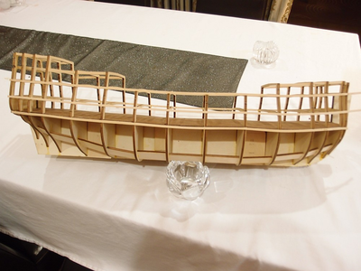
Additional reinforcements were made to ensure hull rigidity. These were made from scrap wood - there is more than enough left over to make these parts!

At this point, I chose to install the lower gun deck. This deck has notches for the bulkheads pre-cut, so it made sense to install it to help check alignment. Note that the deck is supplied in left and right halves, but installation is impossible unless it is also cut across the beam (into quarters).

1697520638772.png
1697520655156.png

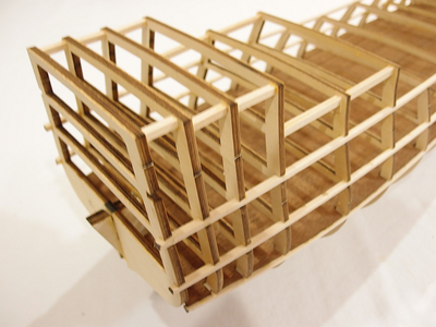
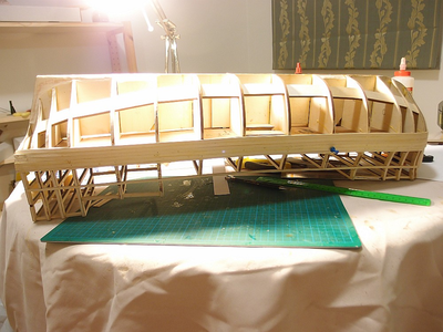
I installed additional reinforcements for the top deck bulkheads. The frame is now incredibly rigid.

1697522168085.png

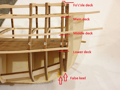
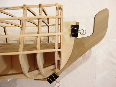
I thought I would draw attention to a problem with bulkhead "F". Note that bulkheads E and F are correctly installed with respect to the false keel. Also, the stringers for the main and middle deck run straight and true - they are so perfectly aligned that they simply fell in! Yet, bulkhead F has a pronounced 1mm step at the level of the fo'c'sle deck, AND the lower deck stringer is bent downwards.
 
Last edited:
It didn't take me long to realize that there were problems with the kit. The Frame "F" thing made me suspect that Euromodel is no Model Shipways, where things simply fall together precisely with minimal fuss. I became even more vigilant for kit errors - e.g. holes or notches cut in the wrong spot, etc. Every move was triple checked with the plans and other build logs. Over the years, a recurrent theme was pre-cut parts not cut correctly to size (and needing shims / corrections / etc), cast metal pieces that are not the same size as the plans, measurements given in the plans not corresponding with the drawings, etc. That I managed to build a decent looking ship despite all the issues was a bit of an accomplishment.
I soon came across this problem:

1697522219869.png


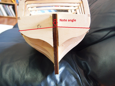
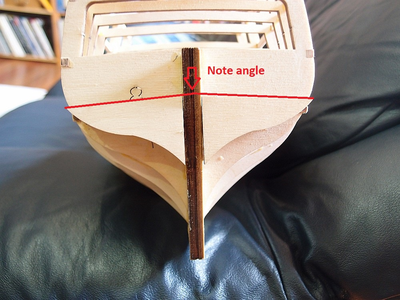
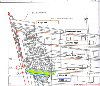
How do I align the rear planking supports (Parts no. 28 and 29) with regard to Frame 8? The plans and instructions do not indicate this clearly. This is VERY IMPORTANT because correct placement of this part determines where the planking will terminate below the transom. Furthermore, if the part is placed as the plans suggest, the upper edge of the part describes an angle, as shown in the red line above! When Keith Julier built his RW, on p.34 he says:

"[...] In my particular case I found I had a little more space than I had casting! This amounted to 2mm in total [...]"

Did Keith Julier place Part 29 wrongly, leading to a taller transom than provided for by the kit, thus leading to his 2mm surplus?

1697522266967.png

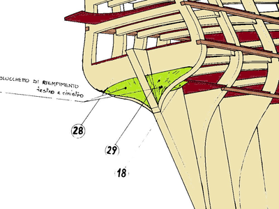
I have coloured in the plans to make them easier to follow. This is what I mean - the plans suggest that the lower edge of Part 29 should correspond with the curve of Frame 8. This was also the approach suggested by Pete in his Interpretive Info.

I have coloured in the plans to make them easier to follow. This is what I mean - the plans suggest that the lower edge of Part 29 should correspond with the curve of Frame 8. This was also the approach suggested by Pete in his Interpretive Info.

1697522311900.png

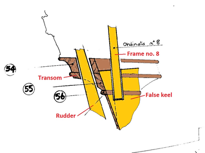
Another view of the same area (from Plan Sheet 7, again coloured for interpretation) suggests that the transom extends below the level of the top of the false keel, therefore the run of planking should terminate slightly above the bottom of Frame 8.

1697522334944.png

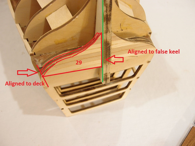
In the end, I decided to align the tip of Part 29 to just below the bottom deck. This means that the lower edge of Part 29 is flush with Frame 8, and the vertical edge of Part 29 is square to the false keel.

Here are a couple more minor kit issues.

1697522367399.png1697522378848.png

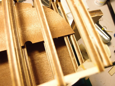
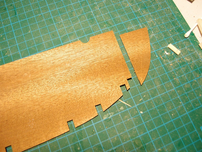
The middle gun deck is supplied pre-cut with a rounded bow section. However, as you can see, the rounded bow section will clash with the front bow filler block. The solution is to simply cut the deck and discard the piece.

1697522410887.png1697522433392.png1697522447319.png


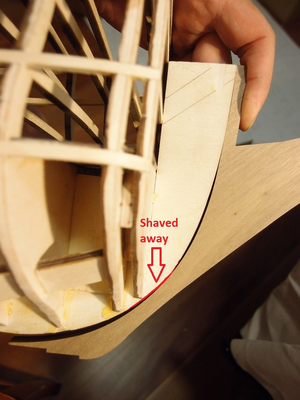
The keel describes a sloppy fit with the false keel. After checking with the plans, and confirming that the top of the keel is supposed to rise to the level of the main deck (if the bowsprit wasn't in the way), I shaved away the area painted in red. I now have a perfectly fitting keel.

1697522468057.png

The kit doesn't include a mizzenmast support, so I fabricated one and installed it.

1697520804385.png
 
Last edited:
1697522541368.png

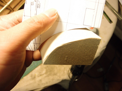
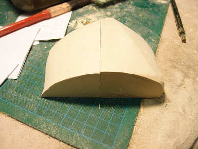
The bow filler blocks were a real pain to fabricate. To help get the correct contour, I photocopied the plans and cut out guides to check the shape at different levels. It really helps that Euromodel's plans are so detailed - by far the best I have ever seen. It more than makes up for the scanty instructions.

1697522553916.png

Completed bow filler block (left). The one on the right was roughly shaped with a belt sander.

1697522571788.png

I used my Proxxon MF70 mill to shape the keel so that they fit together.

1697522587773.png

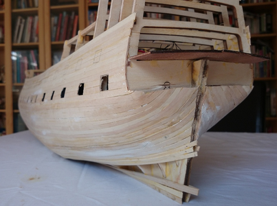
Start of planking! I decided to start at the lower gun deck and go both upwards and downwards.

1697522604489.png

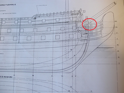
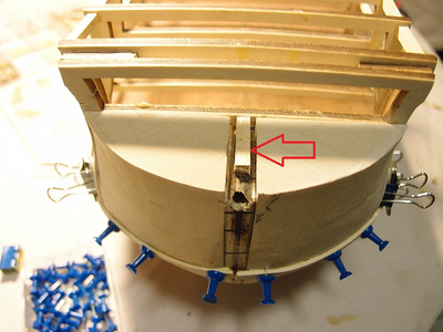
The bow, with the bow filler blocks installed. The plans are rather sketchy regarding how they should be placed, but it made sense to bring them up to the level of the main deck. If you do so, there will be a gap in the middle because the false keel does not rise high enough. I installed a block (arrowed) to help support the main deck which will be installed later.

1697522617991.png

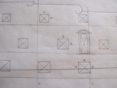
I then started tracing the gunport pattern out onto some tracing paper.

1697522634642.png

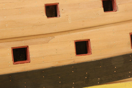
Note that there are FOUR different sizes of gunports. Interestingly, none of the other build logs mention this. Pete's Interpretive Info on the Euromodel website suggests that only TWO different gunport sizes are present (14mm x 14mm, and 13mm x 13mm). The gunport sizes I measured out were:

14mm x 13mm <-- lower gun deck
13mm x 12mm <-- middle gun deck
11mm x 10mm <-- main deck
9mm x 9mm <-- hindcastle

1697522649320.png

I have now installed five planks on the lower gun deck, all without tapering.

1697522682304.png

Thanks to me not reading the (*&^(&^&% plans properly, I cut the gunports 4mm too low! This is me correcting the mistake.

1697522696833.png

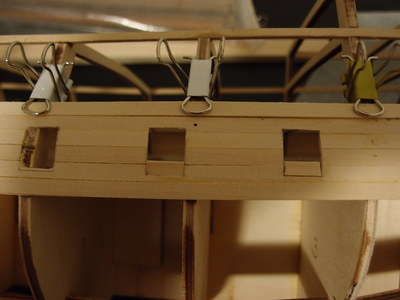
This is my gunport cutting jig. The hole in the middle is where a pin goes through. I mark the position of the gunport with a pin, then place the jig on top. I trace the outline of the gunport, then cut it out using a knife and a drill. It is finally shaped down to the line with a file. If I can pass the gunport jig tightly through the hole, it is the correct size.

1697522712683.png

Planking continues. The lower deck gunports have been cut out and the dummy gun supports have been installed. The lower deck has been painted black.

1697522725305.png

As per other build logs, I installed some nails into the keel to keep it stable because a great heavy mass of metal decorations will be cantilevered off the beakhead.

1697522737081.png

The keel is also attached to the false keel by means of wooden dowels. Even with no glue, the whole shebang is rock solid!

1697522749403.png
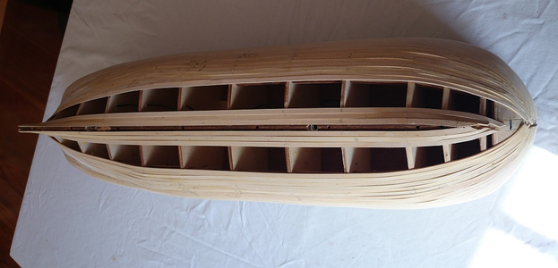
Planking has now proceeded to below the level of the wales, and up to the second deck. Not shown are the blocks to support the dummy guns. These things are virtually impossible to photograph, because they are painted black against the entire lower deck, which has also been painted black. This is a good thing, because I don't want to see the dummy blocks. It IS a bit difficult trying to locate the holes for installation of the dummy guns when everything is black though.

BTW, the second deck fit perfectly a few weeks ago when I was fettling it. Now, with all the planks in place, somehow the deck won't fit! After quite a bit of cursing and a lot of anxiety (did I somehow distort the shape of the ship when I planked it?) ... it all measures correctly. Phew.

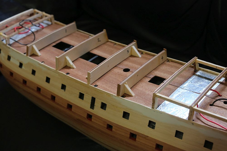
As you can see, the second deck is also painted black. The rear section has been covered with foil for lighting.

1697522764296.png

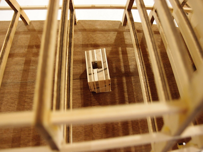
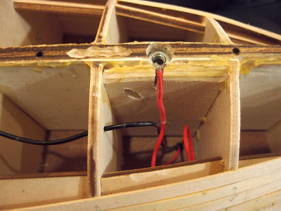
I was not sure how to route power into the ship. You can see a little excavation which I dug out on the false keel because I was planning to put a connector there. Then I hit upon a simple idea - why not simply electrify the support rods that I was planning to install anyway? I soldered the wire unto a nut and installed it.

1697522775446.png

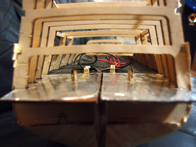
We have no lights ...

1697522787940.png

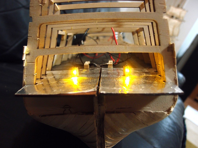
AND NOW WE HAVE LIGHTS! EUREKA!! The idea worked!!!

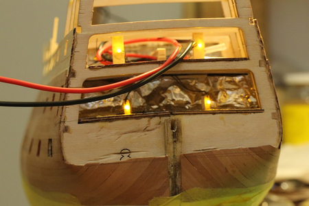
As you can see, the LED's are SMD's (surface mount diodes) which are absolutely tiny. I glued them to a block of wood and then angled them outwards slightly. Yes, I know that Euromodel supply metal plates in place of windows, so you will never see the LED's if you build the ship as per the kit. However, I plan to fabricate my own replacement windows. I'm not sure how i'm going to do that, given that I have never made windows as small as this before, but time will tell ... I'll think of something! I hope!
1697522808399.png

1697522818626.png

1697522832823.png

Even more progress with planking.
 
Last edited:
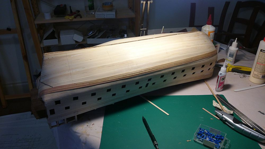
Completed the first planking up to the main deck level. To my immense relief, the planks are still straight, which means that each deck installed so far is exactly parallel with respect to the others.

Other builders of the RW the other forum decided to continue the first planking upwards, but I am nervous about doing this. Any planking above the main deck is unsupported by frames, and thus potentially vulnerable if the ship is turned upside down.

I have therefore decided to start my second planking at the waterline and work downwards and upwards. These photos show that the waterline has been drawn with a thick black marker.

If you look closely, you will note that I am using pear strips which I bought from Jeff at Hobbymill for the planks above the waterline, and the Euromodel supplied strips below the waterline. The reason is to save cost by saving the expensive pear strips for planking which will actually be visible. The planks below the waterline will be hidden by white paint.

1697522909127.png

1697522923602.png

The 2013 edition of "SHIPWRIGHT" magazine has a feature by Mr. Yankovitch who scratchbuilt the 1:36 scale Royal William. It is well worth reading, he talks about his technique and how he overcame various problems. I bought my copy on Kindle. Amazon link is here:

http://www.amazon.com/Shipwright-20...id=1416144214&sr=1-1&keywords=shipwright+2013

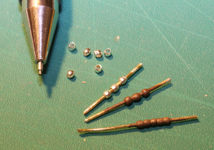
The kit does not supply any balustrades. It is difficult to source balustrades which are the right scale, most aftermarket balustrades seem to be rather large and out of scale.

Solution? Visit my local bead shop.

1697522942063.png

These beads are 1mm in diameter! You can see them compared to the tip of my mechanical pencil, which uses 0.5mm lead. Thread a few of these on wire, fix with superglue, and they look OK when painted. Yes, I know it looks disturbingly like poo, or maybe meatballs on a stick, but that was the only shade of brown I had in my cabinet!

1697522960666.png

The second layer planking has almost reached the keel. Why so slow?

1697522974196.png

This is because I have cheaped out and i'm using the kit supplied second planking material for all planking below the waterline, which will be painted white. This meant splicing the kit strips with the pear strips I bought from Hobbymill. I should be able to reach the keel sometime this week. After that, lots and lots of sanding. Then I will line off the gunports and start the second planking upwards.

1697522991686.png

All planking below the waterline is done, and the hull sanded down. It is smoooooooth.

1697523020804.png

I made a decision to stop all work above the main deck level and complete planking below the waterline first. This was because I knew I had to invert the ship and did not want the delicate structures above the MDL to be vulnerable. As you can see, this planking is unsupported. The planking above MDL survived ... until I inverted it to sand the bottom. Because this generates so much dust, I do it outside. CRACK, the inevitable happened.

I was never happy with the planks above the MDL anyway. I will rip out both sides and start again.

1697523035578.png

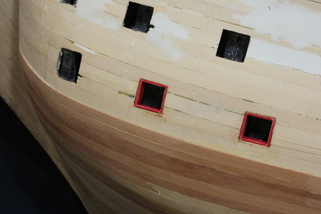
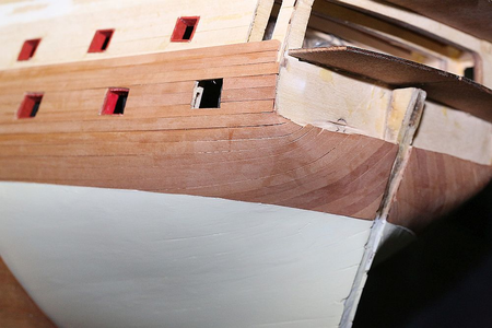
I also made a start with the gunport lining. I am not sure of the shade of red I have chosen (Vallejo Flat Red). To me it looks a bit like lipstick. I have a more dull red in my cabinet (Admiralty Models Red Ochre) which IMO is too dull. I might persist with it for now.
 
Last edited:
1697523074519.png

I was not happy with the planks above the main deck level. As mentioned earlier, these are unsupported. On my first attempt, I slowly glued the planks with CA. It turned out OK, but after sanding the planks they became thin. After inverting the ship a few times to work on the second planking, the inevitable happened and they became warped.

I was determined not to make the same mistake twice. I fabricated some temporary bulkheads and started again. Now that I have something to clamp the planks to, I was able to use my preferred cement - PVA.

1697523086302.png


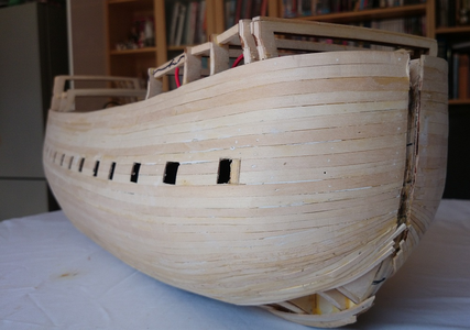
After the glue had dried, I proceeded to cut out the gunports. I wanted to do this as quickly as possible so that I can install a double thickness of first planking material to stop it from warping again.

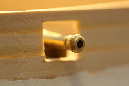
To locate the gunport, I threw together a kit cannon, along with some planks I will be using for the deck to gauge the correct height. A pin was pushed through the planking, and the height checked against the gun barrel. Once I was happy with the location, I mounted my square template on the pin (see earlier posts) and drew out a square. A steel ruler and a scalpel ensures neat cuts. The hole cut out, the cannon is mounted again to check if the position is satisfactory. As you can see, it is perfectly OK!

1697523113970.png

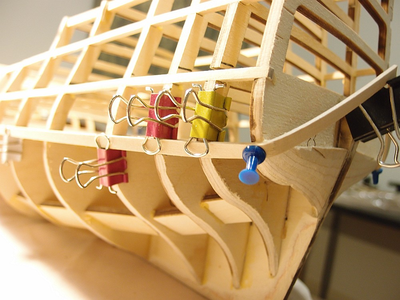
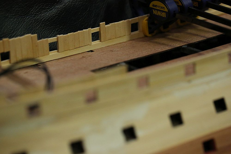
Once the gunports were cut out, I started to install the layer of first planking. As you can see, I am installing it perpendicular to the first run of planks. Hopefully this will give it extra strength. I clamped down each run of planks to ensure the fit is tight. You can also see that I have extended the planks at the fo'c'sle to support the extra planks that will be installed there.

Oh yes, you can also see in the last picture - I have now extended second planking to above the level of the lower deck gunports. I decided to paint over the gunports with red ochre, and it is a much more pleasant shade of red than the rather lipstick-like Vallejo flat red.

I made a major blunder!

1697523142665.png

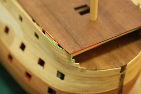
When I test fit the fo'c'sle, I saw that the deck ends well ahead of bulkhead F. Given that bulkhead F is tapered with respect to bulkhead E, you would THINK that the planks ahead should be curved. So I indeed curved my planks ahead of bulkhead F, following the line of the main deck. As you can see from my diagram, the green line I have added shows my planks curving underneath where the deck is supposed to end.

A quick check of the plans confirmed that I had indeed made a serious error. Now I faced a choice of terminating the deck early, or trying to bulk up the bow planking to accommodate the fo'c'sle deck.

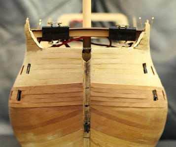
I chose to do the latter. Which meant that I faced an additional problem of how to fair the planks in without distorting the shape of the bow too much. I pored over pictures of the completed ship, which at least assured me that mistakes here would be covered by the beakhead rails. I also studied closely other build logs on MSW for help. So far nobody has mentioned this issue.

Oh well.

1697523155078.png

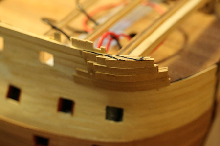
I started bulking up the planks by laying strips of second planking material.

1697523169092.png

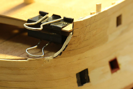
Once done, I trimmed it back.

1697523180788.png

I think it looks OK!

Some of the stuff I talk about might be really boring for those of you not building this ship, but i'm putting it out there for the benefit of other RW builders.

1697523198330.png

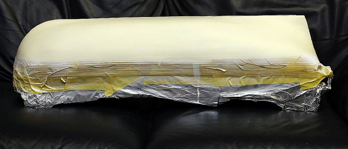
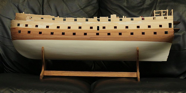
I drew the waterline, then masked it off and painted the bottom white. I first applied 3 coats of Tamiya's white primer, sanding down each layer with 400 grit sandpaper. I then applied four dilute coats of Vallejo "Ivory White", again sanding down each coat. It is now really smooth!

1697523210554.png 1697523223482.png

I just LOVE removing masking tape, it's better than opening Christmas presents! I was rewarded by a clean paint line. If I DIDN'T get a clean paint line, I would have had to sand it down and paint again. I allowed 48 hours for the paint to cure, then wrapped the whole thing up in masking tape again to protect the white finish while I work on the rest of the boat.

1697523235522.png

I then moved on to tackle the transom support. This involves carving two pre-shaped pieces down to the correct size.

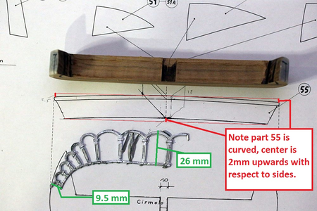
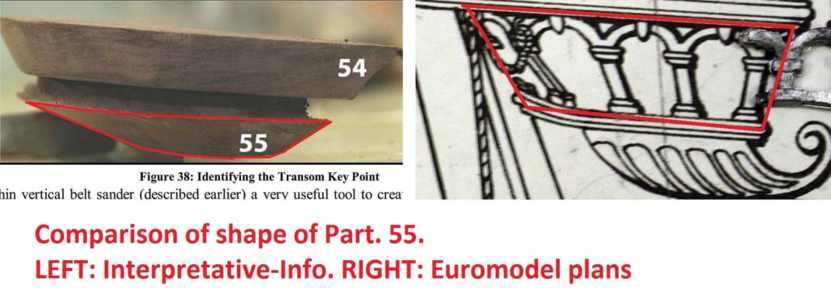
Keith Julier calls this the most challenging area of the build. Piratepete's "interpretative info" devotes 8 pages to discussing this subject. Indeed, the shaping of the rear transom support is not easy and is NOT helped by the plans giving a completely misleading suggestion of the profiles of pieces no. 54 and 55. The true shape of the lower support piece Part. 55 is hinted at by looking at Plan Sheet No.8, but even that does not reveal its exact shape because it is shown hidden under metal decorations (more to say about the accuracy of these plans in a moment). Indeed, if you take a look at the diagram above, it would appear that the suggested taper on Part. 55 is fairly gentle.

NOT SO! Take a look at PiratePete's I-I. Observe the severe taper on the lower piece:

1697523250662.png

It is as I suspected. There is no way to correctly determine the shape of this transom piece prior to shaping it. This SHOULD cause considerable anxiety, because the metal decorations have to fit in the space above it. Get the shape and thickness of this wrong, and you will either overcrowd your metal pieces, or have empty spaces in between!
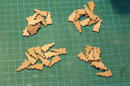
The only way to correctly determine the shape would be to test fit the metal arch decorations which should be attached to Part. 55. So I got them out of the bag.
1697523269056.png

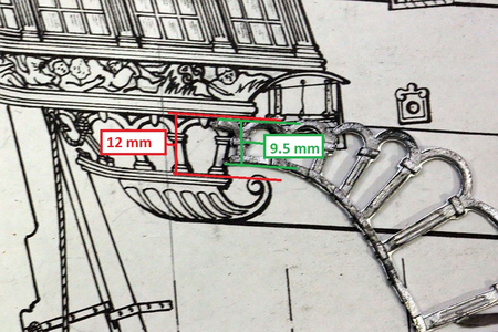
Uh-oh. The plans (which are supposed to be a 1:1 reproduction of the ship) indicates that the height of the arch should be 12mm. But the metal pieces supplied by Euromodel are 9.5mm. Right, so I can't trust that the metal pieces supplied will actually correspond with the plans, then! Talk about flying blind!

* And yes I am aware that both Julier and Pete say that the plans indicate a scratch built model. However, it would have saved considerable anxiety if Euromodel had produced parts that actually fit the plans or vice-versa in the first place.

1697523281576.png

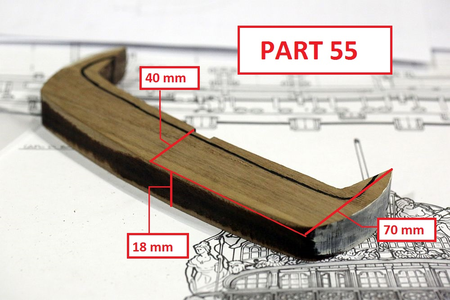
I decided to work out the correct dimensions needed by using some maths. Above is the transom support piece which has been shaved internally so that it fits the model. I have supplied dimensions of the piece as supplied by Euromodel. You can also see that I have painted the side white to help make it easier to see any markings I need to make on the piece.

1697523298687.png

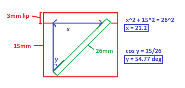
The last time I touched Pythagorean theorem and trigonometry was in high school, more than 20 years ago ... so I was a little nervous about doing these calculations. It looks as if the width of the piece (40mm as supplied by Euromodel), should be reduced to (21mm + allowance for curvature of the metal arch + allowance for support piece 56). I will bring it down to 30mm as a start, then check everything for fit.
 
Last edited:
As preparation for tackling the dreaded Part 54 and 55, I did a study of the various angles of the various features of the transom, to help shape and locate these parts:

1697523345497.png

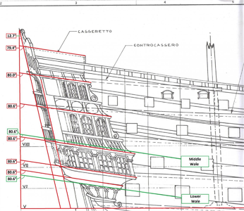
This study locates the rearmost lip of Parts. 54 and 55 with respect to the inclination of the transom. Note that (2) part 55 is exactly in line with with an imaginary line drawn down from the transom, whilst part 54 is projects outwards slightly. Also note that the angle of the lower deck is not the same as the angle of the transom! In fact, Part 54 (which starts significantly below the lower deck) ends up being 5mm below the lower deck at its rearmost projection.

1697523366641.png

This study looks at the various angles of the decks, wales, and features. Note that Pete's interpretive-info admonishes the builder to incline the transom at the same angle as the wales. This advice is 100% correct.

Note also the optical illusion that the higher decks seem to slope less than the lower decks. This was certainly the impression I got when I looked at the plans. Not so! The angle DOES change, but only by 1 degree!

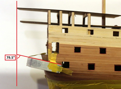
I then transferred all these angles to my model, with the aid of a square and a protractor.

1697523382223.png

As you can see, the marking which I made was more or less spot on.

1697523394720.png

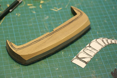
I then proceeded to carve Part 54. I made a paper template of the arch decoration to help obtain the correct shape. Marks were made on the part to stop me from sanding beyond those boundaries.

Other RW builders might feel a sense of dread after reading Julier's description of his difficulty with this part. But then, I have something that Julier doesn't have! (No, it's no talent). I have a Byrnes Disc Sander! All I needed to do was dial in the angles on the sander, then push the part in. Easy-peasy!

1697523410126.png

Within 30 minutes, I had achieved this! Perfectly uniform and smooth. The metal arch template fit perfectly. To say I am delighted would be an understatement. I would kiss my Byrnes disc sander if I wasn't so afraid that it would sand my lips off.

Having successfully shaped this part, I would like to share these observations with fellow RW builders:

1. The thickness of the part as supplied by Euromodel is absolutely correct - 18mm. Do not thin this piece any further.
2. The plan view of the part is also absolutely correct. DO NOT ALTER the plan view.
3. The lower outline of Part 55 can be obtained by aligning transom support piece 56 (supplied as laser cut mahogany ply) with the notch on Part 55.
4. The angle obtained by the above procedure, using a line drawn from the outer edge of Part 56 to the lower 3mm lip margin of Part 55, is 26° (when viewed from the rear), and about 70° (when viewed from the side)
5. Make sure you shape the piece internally before attempting to shape the piece externally.

Next up in this gripping tale (maybe not) ...Part 54 :P
 
Last edited:
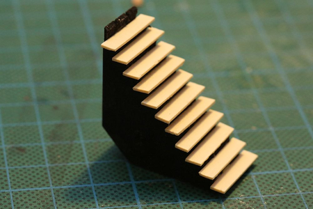
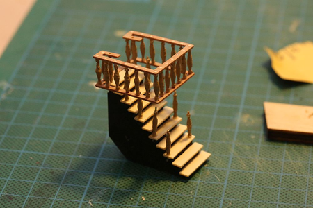
Took a break from fabricating those infernal transom parts to doing something which was more fun. I made the staircase from the main to the lower deck. This piece will be mostly hidden so I used it as a trial run for other staircases I will have to build.

First problem - the balustrades. The kit does not supply any. Commercially available balustrades can not be found in the correct size (or perhaps I am not looking in the right places). The plans suggest balustrade dimensions 9mm x 2mm, and I would agree. 3mm balustrades look too thick and awkward.

I fabricated my own. Those who are following this thread may recall an earlier post (here: http://modelshipworld.com/index.php/topic/7195-hms-royal-william-by-keithw-euromodel-172/?p=278928 ) where I came up with the idea of threading beads on a wire. I refined that idea a little:

1697523464560.png

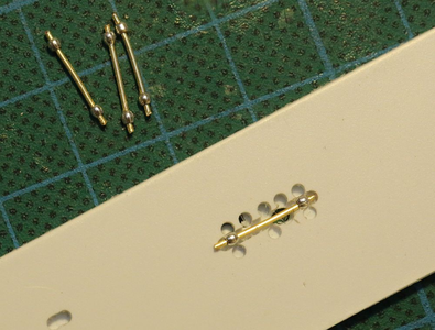
First set up a production line to superglue the beads in place.

1697523479134.png

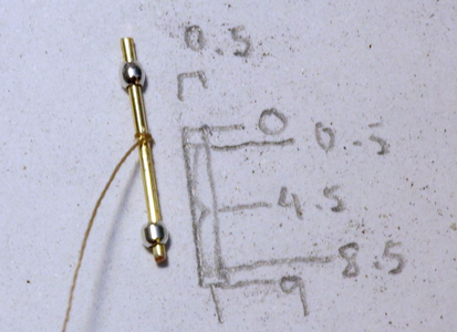
Tie a thin thread to the wire, superglue the knot, then cut the thread flush.

1697523498396.png1697523507155.png

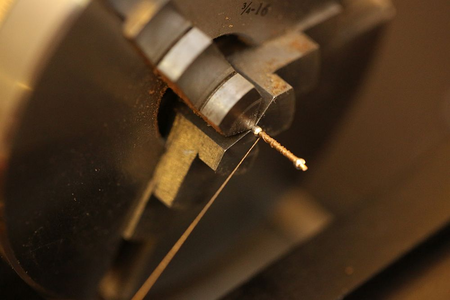
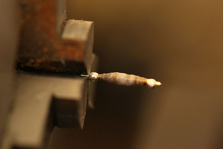
Wind the thread around the wire until a bulb is formed (I used my lathe at very low speed). Keep adding superglue. The idea is to impregnate the thread with superglue to make it possible to turn on a lathe later. Once done, add a layer of liquid sculpey.

1697523521592.png

Bake the batch in the oven according to the Sculpey instructions (15 min at 150C).

1697523533311.png

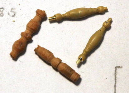
Turn the balustrades on the lathe until happy with the results, then paint. This is a comparison of the BEST effort I made with turning pear dowel on the lathe (on left) with the Sculpey-thread-bead method (on right). The problem I had with turning pear dowels is that they snapped off the lathe once they reach a certain thinness. I could never get them below 2.5mm - still too thick.

To be honest I am satisfied with neither of them. The sculpey-thread-bead method does produce a superior looking balustrade, but it is VERY time consuming, VERY fiddly, and VERY inconsistent. I decided to accept the results since the staircase will be hidden, but I will need to find another method. I might try turning brass or maybe even bone.

Anyway, I continued with construction.

1697523545727.png 1697523560966.png 1697523574278.png
1697523584241.png


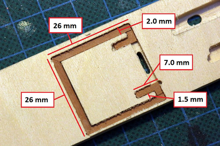
I made a jig to make sure that I aligned the various planks for the handrails properly. I decided not to follow Euromodel's plans and came up with my own dimensions (which I have supplied), because I think it looks better! Once done, I stacked both squares and drilled holes simultaneously through both, to make sure that they would align once the balustrades were fitted.

1697523610091.png

1697523623166.png

Staircase construction. Given that it would not be seen, I decided to simply paint the jig black. It would be more sturdy and easier than constructing an actual staircase.

1697523635298.png

Staircase in position! It is mostly hidden by the quarterdeck. The my Canon macro lens (100mm f/2.8) is ruthlessly revealing but it actually looks pretty good.
 
Last edited:
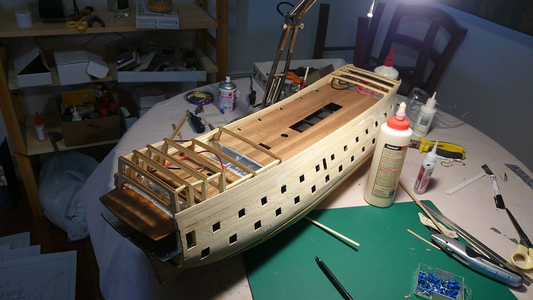
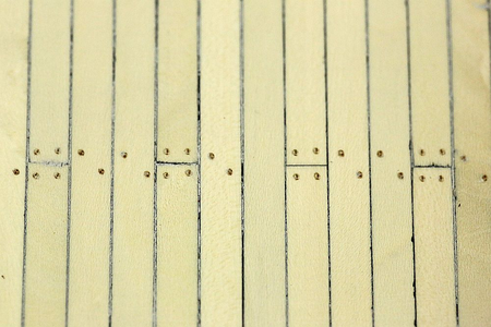
The main deck has been planked and treenailed.

1697523720746.png

The planking was done in a 3 plank shift pattern. I did a few experiments to simulate the caulking, including edge gluing black card, black paper, and black tissue paper. My problem with this method is that the paper tends to tear, no matter how sharp my scalpel is. This leads to caulking of irregular thickness.

In the end, I clamped a whole bunch of planks together and painted both edges. I went over it 3 times to get a decent thickness of paint. Once sanded, it looks OK. I am happy with it!

1697523758986.png

The treenails were made from bamboo, drawn through a Byrnes draw plate. I was initially not happy with my Byrnes plate, because it kept clogging up with wood fiber, and I would have to clean out the plate after each draw! Then I worked out that I was pulling the dowels through the Byrnes plate the wrong way! Once I corrected that, it became a dream to use. These bamboo dowels have been pulled down to 0.5mm. The effect against the holly is subtle, but it's exactly what I want.

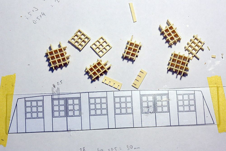
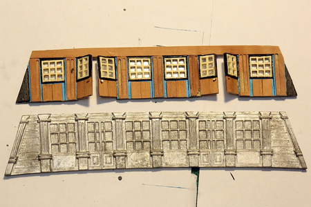
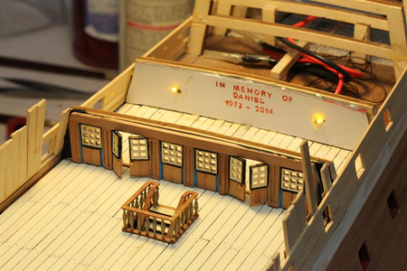
I then decided to make a replacement cabin piece. As mentioned earlier in the thread, this is supplied as a cast metal piece which should be painted and then fit to the bulkhead. There is no other word for it - this piece is hideous. Thankfully it is hidden away under the quarterdeck, so I could have gotten away with using it if I felt lazy. But I thought I would give it a whirl.

1697523842638.png

1697523857087.png

This is what I enjoy most about modelling ... actually making stuff out of wood! The windows were made by cutting slits in some thin holly and fitting it together as you would fit grating. It was then thinned down on my disc sander down to 1mm, then glued on a sheet of clear styrene.

You can see this piece compared to the chunky metal piece supplied by the kit. I would normally discard it, but I found a use for it.
1697523886401.png

... I painted it with a hidden message to remember my best friend who passed away last year. I also installed some lights to light up the cabin from within.

1697523911088.png

The stern LED's have also been fitted.
 
1697523965007.png

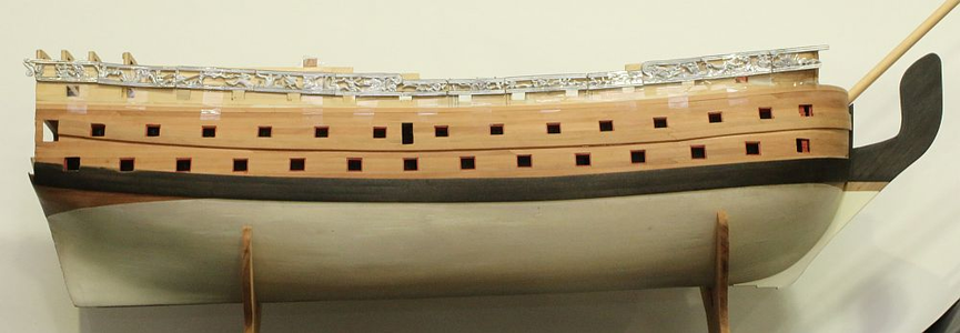
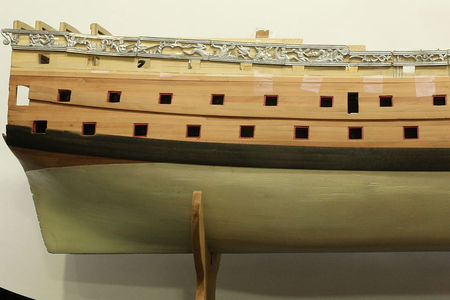
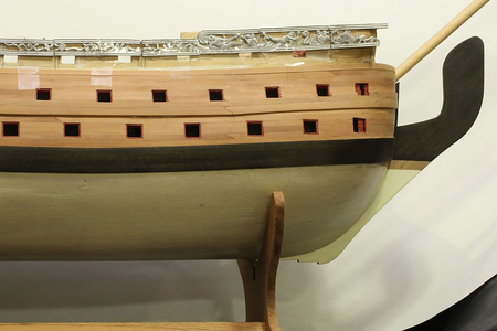
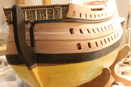
The wales have gone on the ship. The vertical bend was first achieved by soaking the wood for 48 hours, and then clamping it tightly to a jig. Once dried, they have to be used within hours of being removed from the jig, otherwise they will straighten up again!

The lower wale was made from kit supplied walnut, dyed black. Once lightly sanded, the lustre of the walnut shines through the black.It is a marvellous (but totally unintended) effect. The walnut wale was incredibly difficult to get on. As noted by others, Feast Watson stains reject CA glue, even though they are water based! My first effort resulted in the wales falling off time and again until I thoroughly sanded off all the stain from the contact surfaces.

The upper wale was made from pear, which I milled from a block supplied by Hobbymill. Pear is a much nicer wood to work with - it is softer, finer grained, cuts cleanly, and much easier to sand. It was MUCH easier fitting the pear wales than the walnut thanks to its bending properties. My first attempt at finding the line of the upper wale involved tediously reading the plans, but then it was much easier to simply run a compass across the top of the lower wale.

Once done, the metal pieces were test fitted.

1697523989123.png1697523999188.png

This is a close-up of the metal pieces. You can see the difference between the metal pieces at the stern (which I have cleaned of all moulding flash), and the metal pieces at the bow, which I have not yet touched. Note that the total length of the pieces is more than adequate to cover the length of the ship, even will the side strakes taken into account.

Having done all that, I started work on the deck furniture.

1697524021800.png

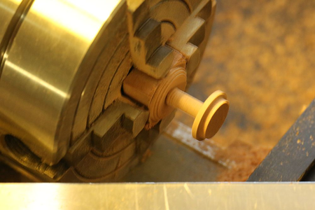
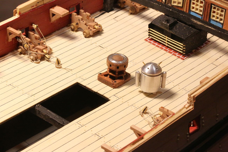
I was not happy with the kit supplied capstan, so I turned my own on the lathe. It took me all day to make a capstan. Why?

1697524033203.png

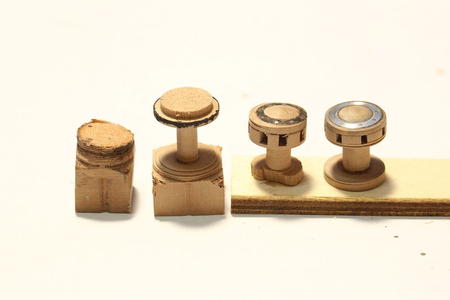
Because of numerous failures and because i'm still learning how to use my lathe properly! Here are the failures lined up before my final successful attempt on the right.

1697524075660.png

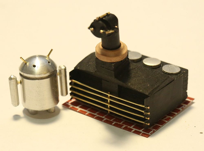
I also fabricated the ship's stove. Note that I have deviated from the plans suggested by Euromodel. Euromodel suggests that the chimney is square and opens up directly to the sky. This means that any rain or seawater will fall directly into the fire, quenching it. My research suggests that chimneys were angled rearwards, and had a moveable cover - so that's what I made.

The rest of the stove will be hidden below deck, so I did not bother detailing the stove very much. There IS detail from where the stove can potentially be seen - from the back (peeking below the deck), from the top (through the grating), and from the side (through the gunports). But the front of the stove is pretty much left as it is.

The "bricks" that the stove is sitting on is simply painted plastic. I could have done a much better job if I had used masking tape, but I decided that nobody is ever going to see my shoddy paintwork, so I painted the bricks freehand.

1697524115409.png

I have also made a start on the gun carriages. I first attempted to make these on the milling machine, but after cranking those knobs I became fed up very quickly. It was MUCH faster to make them on the table saw!

1697524162544.png

The scratchbuilt gun carriages have been completed - along with eye rings, simulated rivets, and quoin. The quoin handles were made from the heads of the smallest belaying pins I could find at my hobby shop (Float-A-Boat). At $2 for a pack of 10, this sure beat trying to turn them myself.

1697524188245.png

A comparison of the kit supplied gun carriage and the scratchbuilt version with my 1/72 scale Android. You can see that it is exactly the same size and height. I ignored the suggested dimensions in the plans because I located the height of my gunports using the kit supplied carriage. This meant that I had to take the measurements off the kit supplied gun carriage but use a design which I completely copied from Chuck Passaro's practicum on MSW.

You may wonder why there is a red stripe there. The answer - it makes it much easier to paint later. I painted the plank and installed it. That way, you get a nice, sharp line without having to mask. I haven't gotten around to painting the rest yet.

You can also see that I have pre-drilled the holes for the gun rigging ... BEFORE the second planking layer goes on. This was a bit of foresight to prevent accidentally drilling holes from the inside to the outside and ruining the outside finish.

1697524216024.png

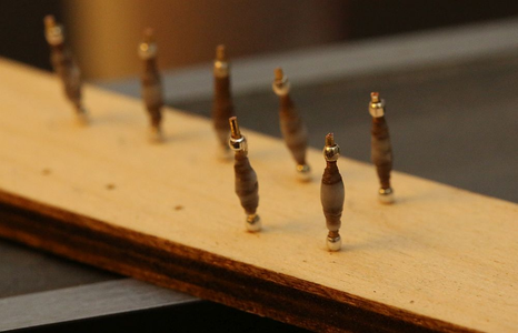
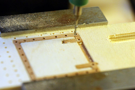
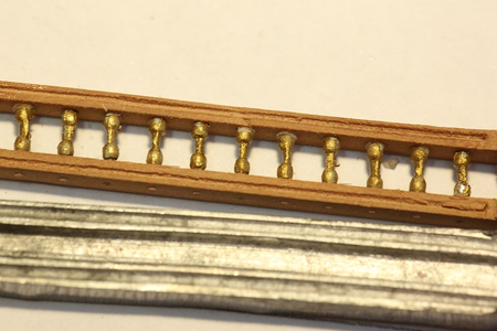
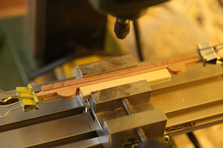
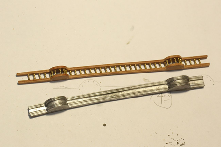
I decided to scratchbuild the decoration that goes above the front bulkhead as well. Two strips of pear were cut with the table saw, then run through the thickness sander until they were 1.8mm thick each. They were then lightly glued together with PVA (generic PVA, NOT Titebond!). The required outline was drawn out in pencil, then they were carved together. After this, it was mounted on my mill to drill 40 holes, spaced 4mm apart (I do not own a drill press). This ensured that they were exact duplicates. They then were soaked in water. This dissolves the PVA and the pieces came apart.

1697524240009.png1697524249359.png

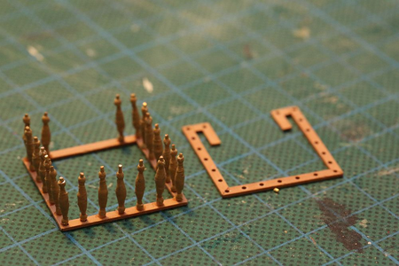
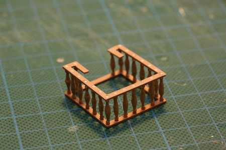
The balustrades were formed with my "bead on a wire" trick described earlier. They were then painted with metal primer (Admiralty paints), then painted gold (Vallejo Old Gold). After 24 hours curing time, they were pushed into the holes drilled earlier and secured with CA.

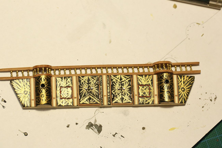
This is a comparison of the scratchbuilt decoration compared with the part supplied by Euromodel. I think the scratchbuilt version looks miles better!

1697524275068.png

I started work on the front bulkhead and the "seats of ease". Measurements were taken from the ship, then a ply template was created. I progressively shaved off wood until it fit the front bulkhead exactly. Here you can see two attempts - the first attempt was created before I realized that I had forgotten to take into account the camber of the fo'c'sle deck! Back to the drawing board, had to make another one.

The seats were formed by cutting a 12mm dowel 60/40, and using the thicker piece. The windows for the seats of ease were turned from aluminum stock on my lathe. I am getting quite good at this now, I have to say! The walls of those round windows are 0.3mm thick!

1697524300722.png

Front bulkhead completed and painted.

1697524353565.png

For other RW builders: this is how the front bulkhead is located with regards to Frame 8. Note my mistake with terminating the planking early (earlier posts describe how I fixed it, but I didn't fix it enough). No matter, the second planking will be brought to the level of the front bulkhead and nobody will be any wiser.

1697524380956.png

The front bulkhead dry fitted on the ship.
 
View attachment 400704

The wales have gone on the ship. The vertical bend was first achieved by soaking the wood for 48 hours, and then clamping it tightly to a jig. Once dried, they have to be used within hours of being removed from the jig, otherwise they will straighten up again!

The lower wale was made from kit supplied walnut, dyed black. Once lightly sanded, the lustre of the walnut shines through the black.It is a marvellous (but totally unintended) effect. The walnut wale was incredibly difficult to get on. As noted by others, Feast Watson stains reject CA glue, even though they are water based! My first effort resulted in the wales falling off time and again until I thoroughly sanded off all the stain from the contact surfaces.

The upper wale was made from pear, which I milled from a block supplied by Hobbymill. Pear is a much nicer wood to work with - it is softer, finer grained, cuts cleanly, and much easier to sand. It was MUCH easier fitting the pear wales than the walnut thanks to its bending properties. My first attempt at finding the line of the upper wale involved tediously reading the plans, but then it was much easier to simply run a compass across the top of the lower wale.

Once done, the metal pieces were test fitted.

View attachment 400705View attachment 400706

This is a close-up of the metal pieces. You can see the difference between the metal pieces at the stern (which I have cleaned of all moulding flash), and the metal pieces at the bow, which I have not yet touched. Note that the total length of the pieces is more than adequate to cover the length of the ship, even will the side strakes taken into account.

Having done all that, I started work on the deck furniture.

View attachment 400707

I was not happy with the kit supplied capstan, so I turned my own on the lathe. It took me all day to make a capstan. Why?

View attachment 400708

Because of numerous failures and because i'm still learning how to use my lathe properly! Here are the failures lined up before my final successful attempt on the right.

View attachment 400709

I also fabricated the ship's stove. Note that I have deviated from the plans suggested by Euromodel. Euromodel suggests that the chimney is square and opens up directly to the sky. This means that any rain or seawater will fall directly into the fire, quenching it. My research suggests that chimneys were angled rearwards, and had a moveable cover - so that's what I made.

The rest of the stove will be hidden below deck, so I did not bother detailing the stove very much. There IS detail from where the stove can potentially be seen - from the back (peeking below the deck), from the top (through the grating), and from the side (through the gunports). But the front of the stove is pretty much left as it is.

The "bricks" that the stove is sitting on is simply painted plastic. I could have done a much better job if I had used masking tape, but I decided that nobody is ever going to see my shoddy paintwork, so I painted the bricks freehand.

View attachment 400710

I have also made a start on the gun carriages. I first attempted to make these on the milling machine, but after cranking those knobs I became fed up very quickly. It was MUCH faster to make them on the table saw!

View attachment 400711

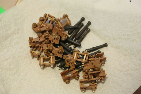
The scratchbuilt gun carriages have been completed - along with eye rings, simulated rivets, and quoin. The quoin handles were made from the heads of the smallest belaying pins I could find at my hobby shop (Float-A-Boat). At $2 for a pack of 10, this sure beat trying to turn them myself.

View attachment 400712

A comparison of the kit supplied gun carriage and the scratchbuilt version with my 1/72 scale Android. You can see that it is exactly the same size and height. I ignored the suggested dimensions in the plans because I located the height of my gunports using the kit supplied carriage. This meant that I had to take the measurements off the kit supplied gun carriage but use a design which I completely copied from Chuck Passaro's practicum on MSW.

You may wonder why there is a red stripe there. The answer - it makes it much easier to paint later. I painted the plank and installed it. That way, you get a nice, sharp line without having to mask. I haven't gotten around to painting the rest yet.

You can also see that I have pre-drilled the holes for the gun rigging ... BEFORE the second planking layer goes on. This was a bit of foresight to prevent accidentally drilling holes from the inside to the outside and ruining the outside finish.

View attachment 400713

I decided to scratchbuild the decoration that goes above the front bulkhead as well. Two strips of pear were cut with the table saw, then run through the thickness sander until they were 1.8mm thick each. They were then lightly glued together with PVA (generic PVA, NOT Titebond!). The required outline was drawn out in pencil, then they were carved together. After this, it was mounted on my mill to drill 40 holes, spaced 4mm apart (I do not own a drill press). This ensured that they were exact duplicates. They then were soaked in water. This dissolves the PVA and the pieces came apart.

View attachment 400714View attachment 400715

The balustrades were formed with my "bead on a wire" trick described earlier. They were then painted with metal primer (Admiralty paints), then painted gold (Vallejo Old Gold). After 24 hours curing time, they were pushed into the holes drilled earlier and secured with CA.

This is a comparison of the scratchbuilt decoration compared with the part supplied by Euromodel. I think the scratchbuilt version looks miles better!

View attachment 400716

I started work on the front bulkhead and the "seats of ease". Measurements were taken from the ship, then a ply template was created. I progressively shaved off wood until it fit the front bulkhead exactly. Here you can see two attempts - the first attempt was created before I realized that I had forgotten to take into account the camber of the fo'c'sle deck! Back to the drawing board, had to make another one.

The seats were formed by cutting a 12mm dowel 60/40, and using the thicker piece. The windows for the seats of ease were turned from aluminum stock on my lathe. I am getting quite good at this now, I have to say! The walls of those round windows are 0.3mm thick!

View attachment 400717

Front bulkhead completed and painted.

View attachment 400718

For other RW builders: this is how the front bulkhead is located with regards to Frame 8. Note my mistake with terminating the planking early (earlier posts describe how I fixed it, but I didn't fix it enough). No matter, the second planking will be brought to the level of the front bulkhead and nobody will be any wiser.

View attachment 400719

The front bulkhead dry fitted on the ship.
Hi Keith, This calls for a Wow! A great build accompanied by an interesting and well documented log. I built one some years ago so I understand some of the challenges that this kit throws up, I wish that I’d had your log as a reference. Keep up your good work on RW. and this excellent log, I’m learning a lot. Ken
 
The main deck has been planked and treenailed.

View attachment 400698

The planking was done in a 3 plank shift pattern. I did a few experiments to simulate the caulking, including edge gluing black card, black paper, and black tissue paper. My problem with this method is that the paper tends to tear, no matter how sharp my scalpel is. This leads to caulking of irregular thickness.

In the end, I clamped a whole bunch of planks together and painted both edges. I went over it 3 times to get a decent thickness of paint. Once sanded, it looks OK. I am happy with it!

View attachment 400699

The treenails were made from bamboo, drawn through a Byrnes draw plate. I was initially not happy with my Byrnes plate, because it kept clogging up with wood fiber, and I would have to clean out the plate after each draw! Then I worked out that I was pulling the dowels through the Byrnes plate the wrong way! Once I corrected that, it became a dream to use. These bamboo dowels have been pulled down to 0.5mm. The effect against the holly is subtle, but it's exactly what I want.

I then decided to make a replacement cabin piece. As mentioned earlier in the thread, this is supplied as a cast metal piece which should be painted and then fit to the bulkhead. There is no other word for it - this piece is hideous. Thankfully it is hidden away under the quarterdeck, so I could have gotten away with using it if I felt lazy. But I thought I would give it a whirl.

View attachment 400700

View attachment 400701

This is what I enjoy most about modelling ... actually making stuff out of wood! The windows were made by cutting slits in some thin holly and fitting it together as you would fit grating. It was then thinned down on my disc sander down to 1mm, then glued on a sheet of clear styrene.

You can see this piece compared to the chunky metal piece supplied by the kit. I would normally discard it, but I found a use for it.
View attachment 400702

... I painted it with a hidden message to remember my best friend who passed away last year. I also installed some lights to light up the cabin from within.

View attachment 400703

The stern LED's have also been fitted.
Awesome work, amazing.
 
Thanks guys! I took a break from migrating posts (we are only 1/3 of the way there) so I am continuing now.

1697536204921.png

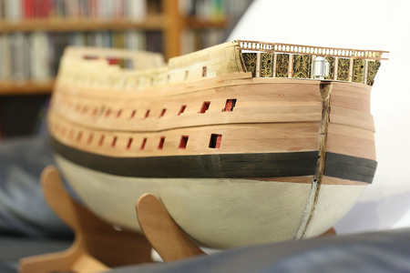
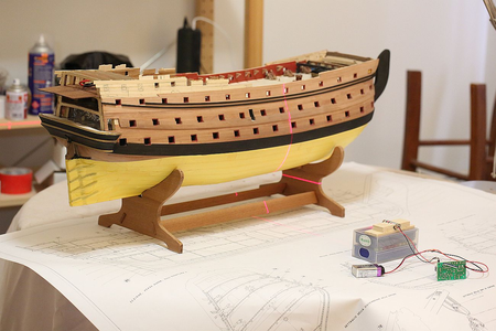
The second planking has been carried through to the top. Above this level will be painted black ... and I still have plenty of pear strips left. I think I will save them and revert back to kit supplied second planking material, since it will be hidden under the paint.
Other RW builders might notice that ALL the cannon ports (except for the first ones at the bow) are open and can receive cannons! This involved a little bit of engineering to hack away at the bulkheads blocking the cannon openings and finding other ways to reinforce the bulkheads. Because I needed more cannon to fill these open ports, I ordered more from Euromodel. They arrived from Italy in less than a week.

1697536230139.png

Don't worry, that smiley face will be hidden by a gun port. Yet to clean up the bow area. Will leave final sanding till after I install the treenails. Waiting for my laser marker to arrive before doing so.

1697536252047.png

Rear bulkhead and stairwell dry fitted, and illumination tested.

I have encountered another contradiction in the plans. I suspect that nobody out there can help, given that I am the only RW builder so far to have reached this particular stage of construction.

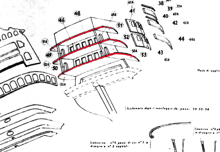
Right now I am looking at construction of the stern decks and decorations. This involves fitting a side trim (supplied by Euromodel, Parts 53/53A,52/52A, and 51/51A):

1697536308804.png

Note that the side trim parts are depicted flush with the deck.

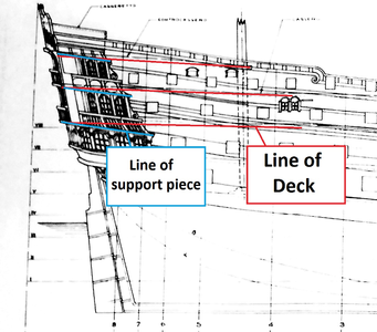
However, this did not look right to me. The decks do not follow the transom inclination, which means that the side trim parts would be at a different angle to all the features constructed below it. I looked at the other plans, and sure enough:

1697536339030.png

Another plan sheet suggests that the side trim parts are angled differently to the deck, and therefore are NOT flush with the deck.

I consulted my usual references to see how others dealt with the problem. Julier does not mention it. As for Pete, on p.34 onwards of his Intepretive Info", he constructs a new deck.

Something tells me that I will need to chop off BOTH the quarterdeck and the poop deck, and construct new decks in order to achieve the correct inclination. Perhaps the quarterdeck only. This then raises all sorts of questions as to how I am going to support a deck which is essentially hanging in thin air, and with a whole bunch of heavy metal decorations to be cantilevered off it later.

It is very difficult to take measurements off decks which are flexible and hanging free in the air! I ended off chopping both the quarterdeck and poop deck, and adding all sorts of reinforcing structures to keep them stable.
 
1697536555725.png

I have now attached the quarter deck. Prior to this, I installed supports for the marine walk and rigged the gun carriages that will be inaccessible once the quarterdeck goes on.

Euromodel does not supply enough gun carriages for this deck - instead, the guns that will be hidden below the quarterdeck and fo'c'sle are dummy guns mounted on gun blocks. I was not happy with this arrangement, because the blocks can potentially be seen. So I ordered more guns from Euromodel. They arrived incredibly quickly, and I should thank Massimo for including a couple of free gifts with the package. I received some cannonballs, and a few buckets and things.

1697536576716.png

Even with my scratch built capstan, I was not satisfied with its appearance. When I visited the Batavia Museum in Fremantle, I saw that that model had a capstan with a base and locks on it. I thought it looked really good, so I copied that idea. This looks much better than a naked capstan sitting on a deck.

1697536599231.png

My laser marker arrived so I started the treenailing a few days ago.

It is a cross-type marker. The horizontal line was taken against the keel, and the vertical line aligned with a set of plans to tell me exactly where the frames are.

1697536666085.png

Treenailing done on starboard side. The treenails were bamboo, pulled through a Byrnes draw plate.

The Byrnes draw plate is really effective, EXCEPT that the largest hole on the drawplate is to small to accept a bamboo skewer! It would be nice if Jim made a larger size drawplate to pull dowels down to smaller sizes for use on his standard drawplate. It became really tedious, shaving a dozen bamboo skewers down to the correct diameter before I could even use the drawplate.

Then it dawned on me that I own a Byrnes thickness sander and a Byrnes table saw. I pushed the bamboo skewers through the thickness sander, then cut it in half lengthwise with the table saw. Voila, correctly sized bamboo dowels!

The treenailing on the hull was bamboo, but I decided to go with brass wire on the wales to give a bit of contrast.

1697536702718.png

All sanded down. The effect is REALLY subtle, you can not see any treenails at all if you view the ship from arms length!

1697536729019.png
 
At this point I took a 6 month break from this model.

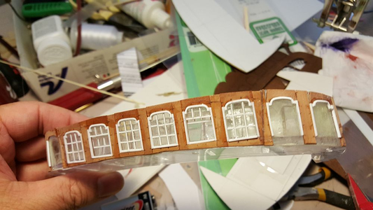
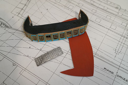
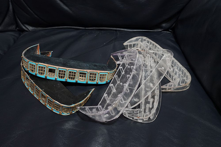
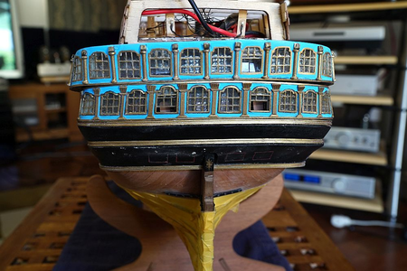
Hi all, i'm back! I took a break because I was frustrated by the first galley on the stern. Having decided to scratch build the stern, and not use the metal plates supplied by Euromodel, I had to come up with a method to make the windows and still let the internal lighting shine through. I thought about building a wooden frame and cutting holes in it, but in the end I decided to make the part out of acrylic and veneer over it.

This is what I am talking about:

1697536805753.png

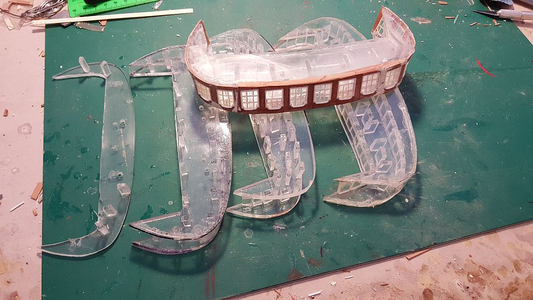
This is a surprisingly complex part to make! The part curves in three directions, and must be precisely cut to fit the lower transom, the deck above it AND the side strakes. You can see my various failed attempts ... I made and remade this part four times. I FINALLY managed to fabricate a piece that I liked.

1697536860518.png

The upper deck will be built together as a unit.

1697536891665.png

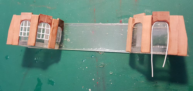
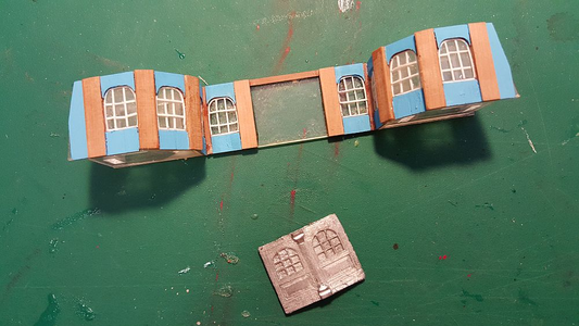
I have also made a start on the next cabin piece. This one is a little more complex, it protrudes out into the deck. Once again, I decided to scratch build the piece myself instead of using the Euromodel supplied plates.

1697536944925.png

Here, the acrylic master is being covered by veneer plates. You can see two methods of constructing the windows - on leftmost, I cut out each cross member and glued it in place (VERY time consuming). The window next to it, I simply laid the cross member across. The difference is not visible if you are looking at the window straight on, but if you look at it at an angle, you can see that the window is not quite right (see later).

1697536969682.png

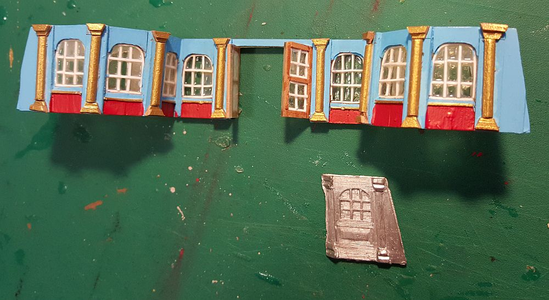
The scratch made part compared to the Euromodel supplied metal plate. I have yet to make the doors. Like the other cabin plates, the doors will be shown partially open.

1697537007187.png

I flattened a dowel by passing it through the thickness sander, then made the feet out of pear. Painted the whole thing gold, and mounted them on the panel.

1697537036082.png

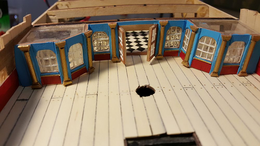
I have also mounted the doors. Yes, I know there are no doors in the plans. Call it artistic license. I have to show off the parquetry floor somehow.

1697537078391.png

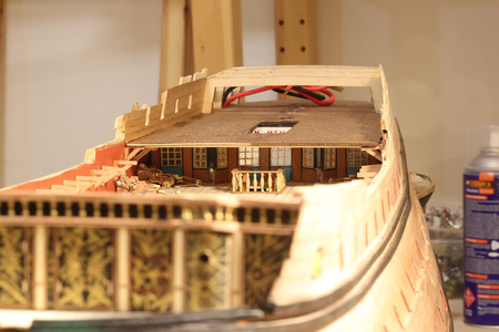
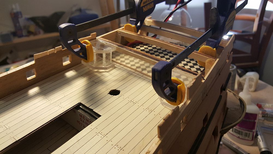
The fo'c'sle deck has now been planked. Note that the marine walk is integrated into the fo'c'sle deck and has been planked with the deck. I am not installing any deck furniture until the ship is fully built up, which is why the deck looks so sparse. Only things that need to be there are there.
 
1697537115708.png

In my previous post I said that I had made four attempts at making the acrylic transom piece. Well, you can make that five attempts. After the last effort, which I thought was "definitive", I discovered several errors. The most serious was that the top piece was far too curved. Quite subtle and not seen in pictures. I only noticed it when I made a final inspection prior to commencing work on it. So I had to fabricate another one.

1697537145015.png

A new feature of the new transom piece is that the acrylic supports are sanded to make them cloudy. This will help diffuse the light from the LED's better.

1697537165423.png

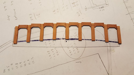
This shows how the galleries in the transom piece are made. The entire piece has severe curves, so it is best built up in sections. The sections are then glued to the acrylic support. The advantage of sections is - if I make a mistake, I can just ditch the section without having to re-fabricate the whole part (which I have already done - five times!). Also, it is easier to bend sections around the curve.

You can see the pencil guides I use to help align window frames. The curved tops of the windows were made on my mill - I milled out a channel from a block of pear, then sliced off slices with my table saw.

1697537206098.png

The windows curve severely around the side of the transom piece. I decided to hide the split under a column. Once it is sanded, painted, and the column decoration goes on, the split will be invisible.

1697537237592.png

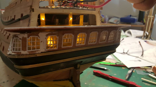
Completed, with wood filler to disguise holes. Whilst waiting for the putty to dry, I thought i'd test out what it would look like with lights on.

If we count all the failed attempts at transom pieces, it would have taken me about 10 days work to get to this point, on this piece alone!

1697537265752.png

Progress as of now. A number of flaws are evident - but nothing some sandpaper won't fix. The windows look slightly opaque - that's my layer of Kristal Kleer drying. Kristal Kleer helps hide any marks on the window - smudges from superglue, accidental cuts, etc. Also, it clings to the side of the frames by surface tension and makes each window pane slightly curved.

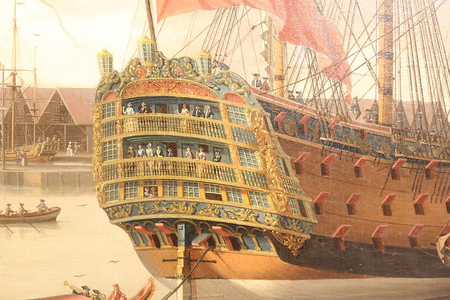
Note there are a couple of open windows. I took a photo of the painting below when I visited the National Maritime Museum in Greenwich. It is of the Royal George, but I have been taking reference off it:

1697537288741.png

The painting shows that the windows open by sliding upwards. I did the same with my transom piece. Hey - it's scratchbuilt. May as well show off.

1697537327582.png

Fabricating this piece alone has taken me longer than it did to build an aircraft carrier when I was a kid.

For those who are curious (and have not been following the build log), this was the process:

- make paper templates. Bottom reference is the top of Piece 54. Top reference is the deck above, which I had to make first. From the deck above, a template was made to ensure the windows had the same inclination as the transom.

- use paper templates to cut out acrylic pieces. Cut out acrylic spacers, then glue both pieces together. Sand the two pieces so that the correct inclination/slope is obtained.

- using acetate sheet, veneer the piece in sections.

- to make windows, route a U-shaped channel through a block of wood. Slice cheeks off with a table saw. Arrange the cheeks on the acetate sheet. Use styrene strips to make the windows.

- sand all the above and paint.

1697537356556.png

The rear of the ship shows the columns. These were made in two parts:

- a dowel was drawn through a thickness sander to give it a D-shape. Styrene strip wrapped and glued around the column. Each window has a slightly different height of column, I had to measure every window and adjust.

- the decoration on top was made by soldering six 0.5mm brass rod together to make a flat piece. Sections were then cut out and bent to shape.

1697537387696.png

Precise, tight fit between the rear piece and the rest of the ship! This is a dry fit, and there are no gaps. Bodes well for later.

1697537414755.png

The lighting for this deck has also been completed.
 
Why, here we are again. What's kept me so busy?

1697537454787.png

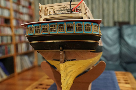
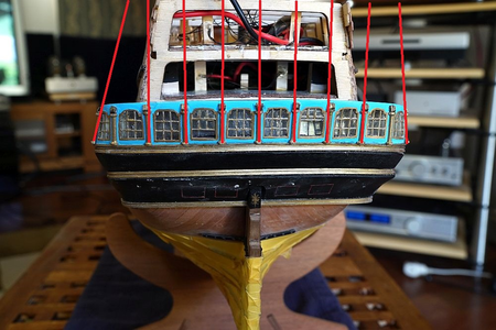
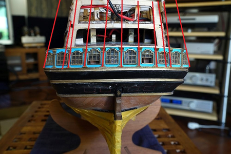
VERSION SIX OF THOSE BLOODY REAR WINDOWS, THAT'S WHAT!!!

You can see that I have actually completed one set of rear windows but decided it's not good enough and attempt another one. Why? Because I didn't read the plans properly.

1697537493042.png

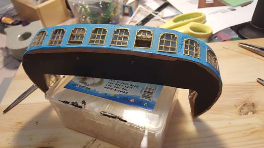
These are the previously completed set of rear windows. I had a feeling that something was not right with the look of the windows, that they looked kind of lopsided from some angles, but OK from other angles. It took me a while to figure it out ... that's when I realized that I had aligned them vertically when I built them.

1697537520385.png

The plans actually call for them to be aligned according to the shape of the hull, tapering towards the apex in perspective. I went through and made another set, paying attention to this detail which I overlooked the first time around.

1697537544002.png
1697537555802.png

I didn't show construction pictures because you know full well how these are made from my previous failed attempts.

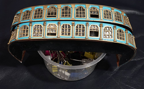
You can see from the above several features of the new part (in the first picture, the new part is sitting on top, in the second picture, it's on the bottom):

1. The angles of the windows which I have already talked about.
2. The new part now has an interior. You can vaguely see it in the second picture.
3. The column decoration on the new part looks neater. I tried a different approach this time.
4. The windows are now outlined in black paint. It makes them look more prominent.
 
With that done, it is time to turn my attention to the construction of the next level deck.

1697537654851.png

This is where I am up to at the moment:

1. The lower deck windows have been completed (see above post).
2. The middle deck verandah (is that what you call it?) has been cut out.
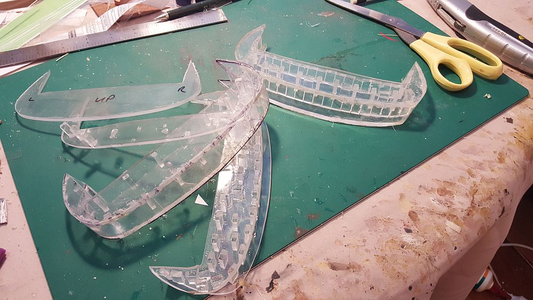
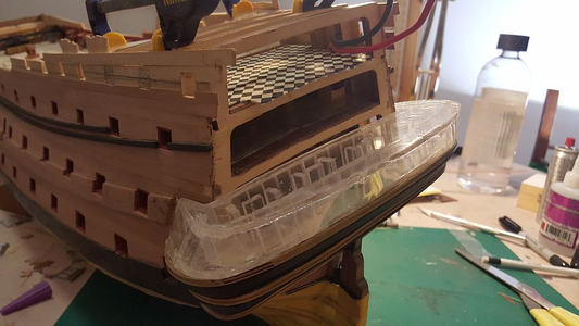
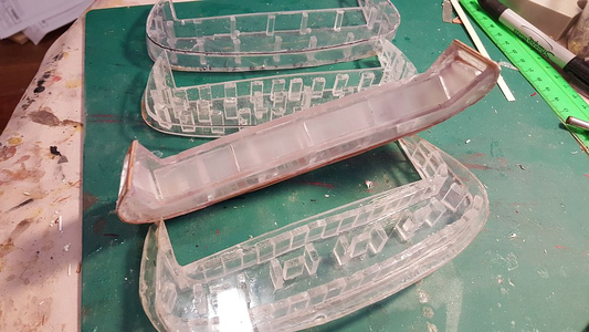
3. Perspex blanks of the middle deck gallery have been shaped. Here you see them being tested for fit. There is a plywood spacer of exactly the correct height helping maintain the upper part in position while I check for alignment. Also note the three pilot holes drilled through both parts - passing a dowel through the blanks brings them into perfect alignment.
4. A cardboard blank of the upper deck verandah has been made (see below).

1697537683798.png

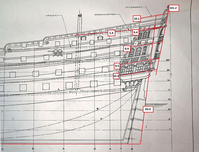
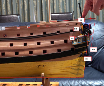
Before I proceed, I thought it would be prudent to check that I have all the angles correct with reference to the plans. I used the keel to take the horizontal reading, then rotated the image in Photoshop.

One thing which has troubled me for a long time is the angle of the poop deck (see below). All the decks are inclined with respect to the wales, but not the poop deck. The poop deck is inclined with respect to the other decks. This is quite unnerving when you install the poop deck, and see that the angle of all the lower decks seem to be off. Not so! this is correct!. The plans say so!

1697537712827.png

Once again, image rotated with Photoshop using the keel as horizontal reference. You can see that the angles are way off with respect to the plans, but to be fair I didn't really take the trouble to center the image correctly (my fault!). By eye they look correct.

A number of decks have now been progressed. Not yet completed, because some of them need to be touched up or redone. Here they are, from the bottom up - incidentally, also showing how tight I have made them fit against the bulkhead:

Note that the angle of the transom is different to the angle of the rudder. There is a substantial difference in angle - 18 degrees! I did not realize this and have been building the transom to accept the same inclination as the rudder. Not too late, all of the decks only exist as prototypes!

1697537751218.png

First, the bottom windows which have been the subject of my last few posts.

1697537777379.png

The middle deck. Note the pattern of the planking. By this stage I realized that I was at least 2mm too tall, so I was trying to save half a millimeter here and there. The deck is carefully planked around the rear gallery to save some height.

Despite this, this part is destined for the rubbish bin. I do not like the effect of the joggled planks, and it turns out that I made this deck about 2mm too wide (which means that when it comes to shave it, it will cut into the joggled planks). I suppose I could ignore it and hope nobody notices ... but I would rather redo it.

1697537810543.png

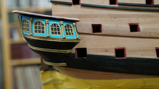
Next, the rear gallery. Columns and doors have not yet been added.

1697537825578.png

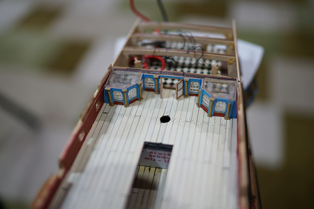
The upper deck. The bottom has been planked, but not the top.

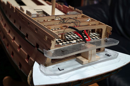
You can see the supports for the poop cabin (to come in the deck above). This is unsupported by any structure, so I decided to make a wooden lattice structure to strengthen it.

1697537864684.png

The upper gallery. As you can see, still under construction.

Note the hole cut through the gallery to accomodate the wooden lattice and the cabling for the poop LED's.

1697537894673.png

And finally, the poop deck. Despite all the effort to save height, I am off by 1mm. The poop deck will have to be shimmed by 1mm to raise it to fit the pre-cut transom. This is the advantage of building the features together (as opposed to constructing the poop deck first as some other RW builders have done) - I am able to adjust features as required.

1697537966928.png

I also decided to excavate some holes for the rear gunports and attach the rear decoration at this point.

1697537987644.png

1697537998555.png

1697538017012.png
 
With that done, it is time to turn my attention to the construction of the next level deck.

View attachment 400760

This is where I am up to at the moment:

1. The lower deck windows have been completed (see above post).
2. The middle deck verandah (is that what you call it?) has been cut out.
3. Perspex blanks of the middle deck gallery have been shaped. Here you see them being tested for fit. There is a plywood spacer of exactly the correct height helping maintain the upper part in position while I check for alignment. Also note the three pilot holes drilled through both parts - passing a dowel through the blanks brings them into perfect alignment.
4. A cardboard blank of the upper deck verandah has been made (see below).

View attachment 400761

Before I proceed, I thought it would be prudent to check that I have all the angles correct with reference to the plans. I used the keel to take the horizontal reading, then rotated the image in Photoshop.

One thing which has troubled me for a long time is the angle of the poop deck (see below). All the decks are inclined with respect to the wales, but not the poop deck. The poop deck is inclined with respect to the other decks. This is quite unnerving when you install the poop deck, and see that the angle of all the lower decks seem to be off. Not so! this is correct!. The plans say so!

View attachment 400762

Once again, image rotated with Photoshop using the keel as horizontal reference. You can see that the angles are way off with respect to the plans, but to be fair I didn't really take the trouble to center the image correctly (my fault!). By eye they look correct.

A number of decks have now been progressed. Not yet completed, because some of them need to be touched up or redone. Here they are, from the bottom up - incidentally, also showing how tight I have made them fit against the bulkhead:

Note that the angle of the transom is different to the angle of the rudder. There is a substantial difference in angle - 18 degrees! I did not realize this and have been building the transom to accept the same inclination as the rudder. Not too late, all of the decks only exist as prototypes!

View attachment 400763

First, the bottom windows which have been the subject of my last few posts.

View attachment 400764

The middle deck. Note the pattern of the planking. By this stage I realized that I was at least 2mm too tall, so I was trying to save half a millimeter here and there. The deck is carefully planked around the rear gallery to save some height.

Despite this, this part is destined for the rubbish bin. I do not like the effect of the joggled planks, and it turns out that I made this deck about 2mm too wide (which means that when it comes to shave it, it will cut into the joggled planks). I suppose I could ignore it and hope nobody notices ... but I would rather redo it.

View attachment 400765

Next, the rear gallery. Columns and doors have not yet been added.

View attachment 400766

The upper deck. The bottom has been planked, but not the top.

You can see the supports for the poop cabin (to come in the deck above). This is unsupported by any structure, so I decided to make a wooden lattice structure to strengthen it.

View attachment 400767

The upper gallery. As you can see, still under construction.

Note the hole cut through the gallery to accomodate the wooden lattice and the cabling for the poop LED's.

View attachment 400768

And finally, the poop deck. Despite all the effort to save height, I am off by 1mm. The poop deck will have to be shimmed by 1mm to raise it to fit the pre-cut transom. This is the advantage of building the features together (as opposed to constructing the poop deck first as some other RW builders have done) - I am able to adjust features as required.

View attachment 400769

I also decided to excavate some holes for the rear gunports and attach the rear decoration at this point.

View attachment 400770

View attachment 400771

View attachment 400772
Continues to amaze me!
 
Back
Top