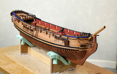
HMS Blandford 1:48 POF Modelship Dockyard [COMPLETED BUILD]

The oil in combination with the colors looks very nice, Ken.
Regard, Peter
Hi Peter. This is the first model that I’d used oil on, I found it simple and I like the finish. I also found that if I mark the surface it’s easy to cover up, just a quick wipe over with oil and not having to re varnish as I previously needed to do on many occasions. I’m a convert.
 
Beautiful transom Ken, you have some of the best faux glass work that I've seen yet!
Hi Daniel, Thanks, I too like the effect that it gives. I learned about this type of glue when I was into RC aircraft, it was specific for attaching clear canopies but when I remembered how it looked I then tried using it for ship windows and found that it worked.
 
Hello, good morning and welcome. Thank you for the many likes and comments that you gave after my last post.

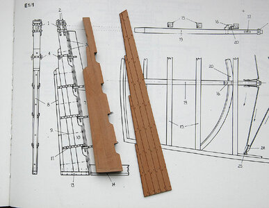
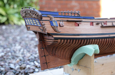
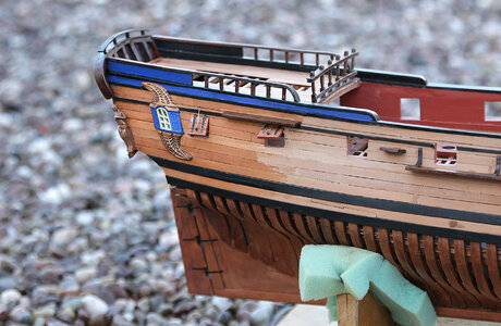
The build continues, this time with the rudder. I’d made the body of the rudder up some time ago ready for when it would be needed. Again no plan or sizing in the instructions but fortunately there is a correct scale drawing in the Anatomy book so I was able to make it up quite easily; it consisted of five pieces which went together well. However when you look at the first picture you will see what the kit would have you build, the shape and size being dictated by that awful pre scribed sheet that is totally wrong, it just wasn’t necessary.

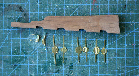
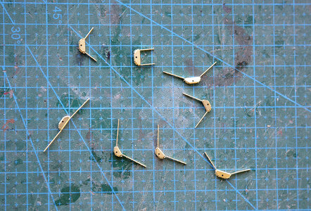
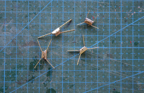
Now to the hinges !!! If they’d wanted to make them more difficult I doubt that they could, it’s one thing having a computer to design things but it’s another for mere humans to make them. At first I didn’t think that they were included as there was no reference to them at all, but I realised that they were included on the very thin photo etch sheet, I hadn’t recognised them at first as they looked nothing like rudder hinges that I’d ever seen before. The pintles were all part of the hinge and needed nine folds of the PE piece to make each side up, as I said there was no guide on doing this and with this type of PE you only get one fold before it breaks off. I eventually worked it out and got the eight pieces made up with only breaking one hinge, I decided to solder the rudder and hull pintles together otherwise there would be no strength in them, it only needed to look right and not have to work, when done I blackened them. Prior to fixing I put a thin brass rod in the rudder to give it a secure fix into the sternpost rather than rely on the hinges for support. After a lot of fiddling and a few choice words I eventually got the rudder into place, it ended up looking ok.

I made up and fitted the gun port lid, I think that other than oiling the hull is now finished except for the deadeyes which are not included with the kit.


357.jpg


428.jpg


430.jpg

431.jpg

432.jpg

433.jpg

434.jpg
 
Last edited:
Hello, good morning and welcome. Thank you for the many likes and comments that you gave after my last post.

The build continues, this time with the rudder. I’d made the body of the rudder up some time ago ready for when it would be needed. Again no plan or sizing in the instructions but fortunately there is a correct scale drawing in the Anatomy book so I was able to make it up quite easily; it consisted of five pieces which went together well. However when you look at the first picture you will see what the kit would have you build, the shape and size being dictated by that awful pre scribed sheet that is totally wrong, it just wasn’t necessary.

Now to the hinges !!! If they’d wanted to make them more difficult I doubt that they could, it’s one thing having a computer to design things but it’s another for mere humans to make them. At first I didn’t think that they were included as there was no reference to them at all, but I realised that they were included on the very thin photo etch sheet, I hadn’t recognised them at first as they looked nothing like rudder hinges that I’d ever seen before. The pintles were all part of the hinge and needed nine folds of the PE piece to make each side up, as I said there was no guide on doing this and with this type of PE you only get one fold before it breaks off. I eventually worked it out and got the eight pieces made up with only breaking one hinge, I decided to solder the rudder and hull pintles together otherwise there would be no strength in them, it only needed to look right and not have to work, when done I blackened them. Prior to fixing I put a thin brass rod in the rudder to give it a secure fix into the sternpost rather than rely on the hinges for support. After a lot of fiddling and a few choice words I eventually got the rudder into place, it ended up looking ok.

I made up and fitted the gun port lid, I think that other than oiling the hull is now finished except for the deadeyes which are not included with the kit.


View attachment 419097


View attachment 419098


View attachment 419099

View attachment 419100

View attachment 419101

View attachment 419102

View attachment 419103

View attachment 419104
Phoe ……. Never seen such filigree rudder hinges. Well done, Ken.
Regards, Peter
 
Hello . A frosty morning so I shan’t be going anywhere today, a good excuse to stay at my workbench with Blandford.

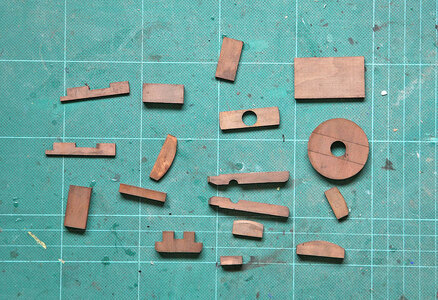
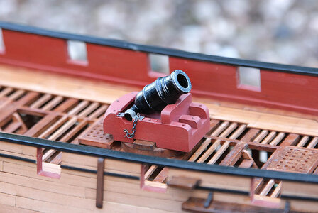
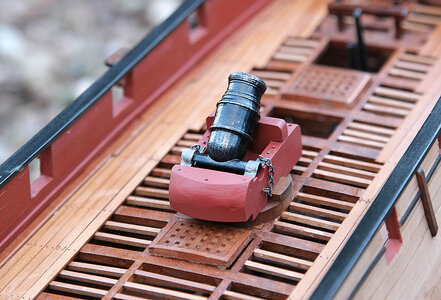
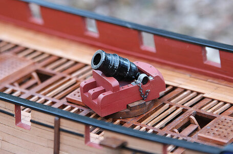
Today I am showing you the completed ships mortar. The manual shows the seventeen wood pieces needed but again does not show how to build it, everyone knows what a mortar looks like and given the pieces you would back yourself to easily put it together. Wrong, I think that Keith may agree it was like a Chinese puzzle, you know the desired shape but you just can’t figure out how to get there with the given pieces. After much trial and error it finally went together with only one piece left over. I painted and detailed it and was quite pleased with the result. The photo of the barrel makes it look shiny but in reality it is matt black with a silver dry brush added. I think that it’s obvious that the mounting on the deck is very wrong and if fired would probably end up in the orlop deck. I wasn’t going to mount it at first but I liked the extra detail that it added to the deck, nobody that I know who would be looking at the model would realise it was wrong but would most likely say, “ I like that “. I was initially going to stain it but eventually decided to paint it as it then balanced more aesthetically with the red capstan.

Have a nice day. Ken


421.jpg

436.jpg

437.jpg

438.jpg
 
Last edited:
Your mortar looks great Ken, I particularly like the paint effect you have created on the barrel. Mind you remember to tell your crew that on no account should they be tempted to fire off a shell as the rebound will see the gun in the bilge! Seriously though it does make a nice feature. Great work as always.

Cheers JJ..
 
I like your oil finish and am glad to hear you are a convert! Be careful, as it makes future glueing difficult, without the addition of pegs to secure additional pieces to oiled areas.

Great build log!

Brad
Hi Brad, Thanks for that. I did have a concern about adhesion of parts on oiled surfaces and I'm working my way around it by only oiling completely finished areas, so far so good.
 
Hello. Again thanks for your comments and likes.

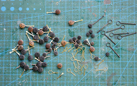
Today isn’t a success story, it isn’t a problem but I wanted to show my failed attempt at making the deadeye strops, I’m sure that most of us don’t always get things right on our first attempt so enjoy my moment knowing that you are not alone in this.

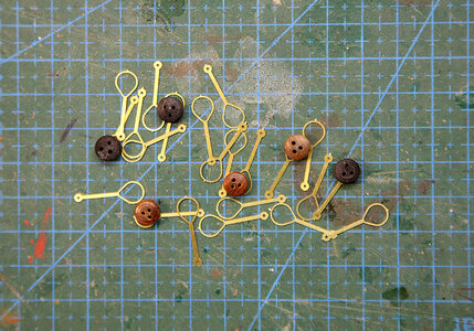
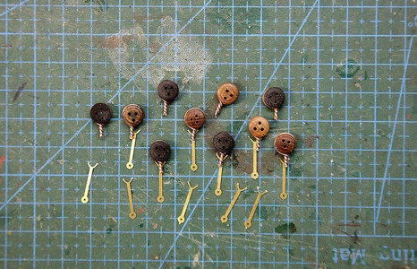
The kit doesn’t supply deadeyes but it does give PE strops, these turned out to be unusable if you wanted to add your own deadeyes without which they would look odd. The ringed part had no opening and was rigid so there was no way to get a deadeye in and seated, also it was an odd size which would make it even more difficult finding suitable ones. I decided to cut the hoop part off, wrap some copper wire around the deadeyes that I had spare and solder it back to the remaining part of the strop, it seemed a good idea at the time. After a days work I realised that the strops supplied were too short, they only just fit if attached straight down, but at any sort of angle they didn’t, secondly as you can see in the pics many of the smaller ones had no eyelet for nailing to the hull, and were too narrow to be able to drill one, I don’t know what their purpose was, so I was left twelve short, it was now back to the drawing board. I have a plan and some brass wire so hopefully I’ll have more success second time around.

The wasted time was my own fault, I should have checked the parts properly for suitability before I started instead of blindly relying on the kit parts, I think that this is another case of a computer designing the parts without taking into account any variables for depth and angles as well as the physical aspect of construction.


What I started with

440.jpg

Looks like it might work

441.jpg

The failed attempt

442.jpg
 
Last edited:
Ken, Here is how I made my deadeyes.
1. Wrapped a wire of appropriate gauge around the deadeye.
2. Made a narrow loop that goes through the hole.
3. Clipped the wire with nail clippers, so the cut edge is hidden by the hole.
4. Made a second wire loop, which connected to the small loop described above, in the deadeye straps.
5. Finally, a third loop which connected to hand produced (painted brass) nailed anchor points.

Maybe there is something in this process that will help on your next attempt, which I'm sure will be excellent!
Brad

Deadeye assembly line.jpg

Deadeye Chainplate anchor montage.jpg

deadeye rails.jpg
 
Ken, Here is how I made my deadeyes.
1. Wrapped a wire of appropriate gauge around the deadeye.
2. Made a narrow loop that goes through the hole.
3. Clipped the wire with nail clippers, so the cut edge is hidden by the hole.
4. Made a second wire loop, which connected to the small loop described above, in the deadeye straps.
5. Finally, a third loop which connected to hand produced (painted brass) nailed anchor points.

Maybe there is something in this process that will help on your next attempt, which I'm sure will be excellent!
Brad

View attachment 419729

View attachment 419731

View attachment 419732
Hi Brad. Thanks for sharing your method, I can see that it works well and is one for the future. The Anatomy book shows Blandford as having a single iron strop rather than links which for me makes it easier to make and as it’s only for appearance and won’t be under tension I can take liberties, it only has to look ok. What’s that you're building, it looks interesting. Ken
 
Hi Brad. Thanks for sharing your method, I can see that it works well and is one for the future. The Anatomy book shows Blandford as having a single iron strop rather than links which for me makes it easier to make and as it’s only for appearance and won’t be under tension I can take liberties, it only has to look ok. What’s that you're building, it looks interesting. Ken
It is my 1st scratch build HMS Serapis. She's completed now. Build log link: https://shipsofscale.com/sosforums/...build-completed-build.6895/page-8#post-350125
 
Hello. Today’s post is as much about success as yesterdays was about failure, so much so that I've been walking around the house with a big grin on my face, my wife thinks that I have finally lost the plot.

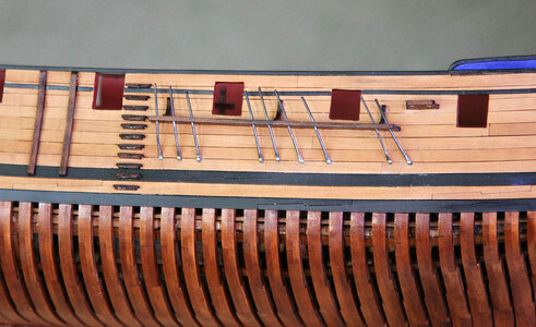
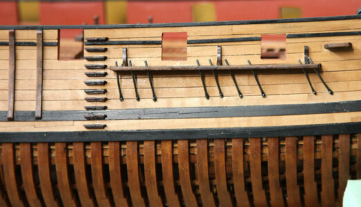
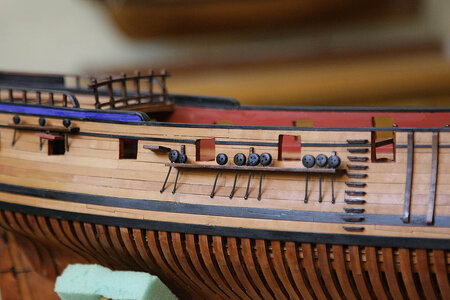
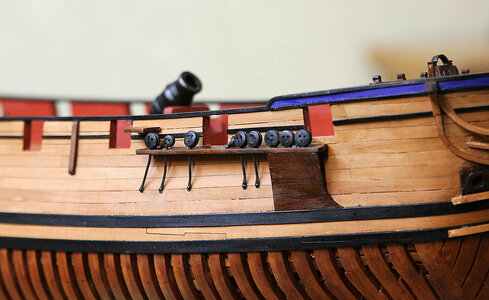
First to make me happy with Blandford again I gave the hull and ribs a coat of oil, it brought all the surfaces together in a harmonious way and seemingly somehow brought the wood alive. I hadn’t thought it possible but the oiled pear is the best finish that I have achieved on my many models to date, mmm, love it.

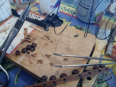
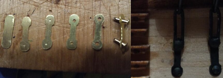
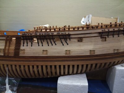
My next success was with the deadeyes and strops. I’ve had my best results by just keeping things as simple as I could so with that in mind I set about making them up. Blandford had single iron strops rather than links so this made things easier for me, they were only going to be for show and wouldn't need to be strong enough to hold the shrouds under tension which again made things easier. I had some 1.25 brass wire which I cut up into oversize lengths, I hammered the ends flat, drilled out an eyelet and filed it round, when done I blackened them in a solution. I put them into the channels, aligned them using the lower eyelet for their position before nailing them into place. I then cut off the excess above the channel leaving about 4mm protruding ready to receive the deadeyes. I stained all the deadeyes to get them a uniform black colour, I drilled a hole in the edge of the deadeyes then slid them onto the strop ends secured with a touch of cyno, job done in very short time. I was initially going to put some wire around the deadeye but found that you couldn’t see that any was missing, even close up, probably due to it being a deep black, so I thought just leave well alone. This turned out eventually to be a very easy and effective solution that I couldn’t improve on.


443.jpg

444.jpg

445.jpg

446.jpg

447.jpg
 
I have found that the lower dead eyes at the chain plates always a pain in the rear. Weather you have kit supplied strops or not they are a pain. You have a new novel way of attaching the buggers to the straps which I like but personally I would have stropped the dead eyes with some black rope material just to fill in the grooved recess around the dead eye.
 
I have found that the lower dead eyes at the chain plates always a pain in the rear. Weather you have kit supplied strops or not they are a pain. You have a new novel way of attaching the buggers to the straps which I like but personally I would have stropped the dead eyes with some black rope material just to fill in the grooved recess around the dead eye.
Hi Daniel. I agree with you in theory, I was going to, I did one using 1mm black thread, when done I couldn’t see the difference. If you were close up and knew what you were looking for yes you would know, I think because it’s a deep black the eye doesn’t pick it out. It’s a very easy task to do and if I start noticing it I can just tie a piece of cord around but at the moment I’m thinking keep it simple and leave well alone.
 
Last edited:
Back
Top