Help! Plans/Details needed for AVANT GUARDE class boats

Joined
Sep 17, 2018
Messages
576
Points
308

Location
Berlin/Germany
Dear friends,


in the next months I will stay a lot of time in hospitals and abroad so there will be no propper work branch for me. Part of my therapy is to focus on a creative thinking and drawing process I have to deal with to fight the damage of my forth stroke.
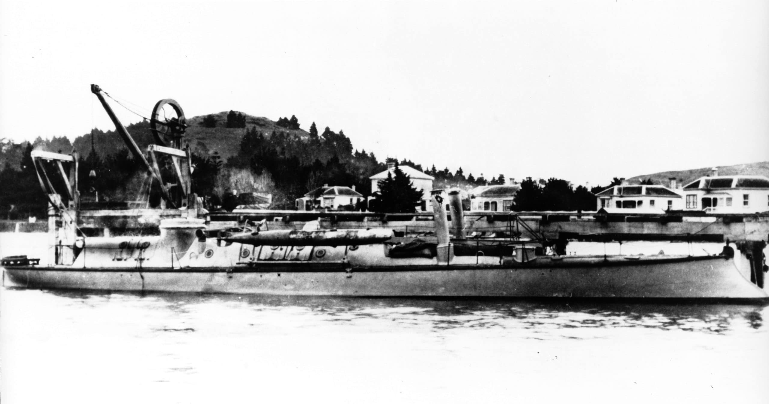
During dealing with my Russian FORELL torpedoboat I learned that all the classes boats were build in France. In my German book about early torpedo boats by Harald Fock "Die Schwarzen Gesellen" {The Back Comrades} (Koehler, Herford, 1979; ISBN 3 7822 0193 0 Pages 328) I found the drawing of very interesting "AVANT GUARDE" on page 86 with several hull-cuts:
Polish_20231023_211220870.jpg

Most interesting of this early torpedo boat type of 1889/90 is the spear (as I do assume it to be telescopic) apparatus to bring as much distance between the dangerous charge and the hull:
Polish_20231023_212107503.jpg

There is a kind of girder structure to keep the wooden or iron apparatus straight - also shown in the frontside cuts' view:
Polish_20231023_212200591.jpg

Offering a bit more of detail to us, as the edged version of the rail part of the apparatus. There are several small errors in the drawings so I urgendly need to deal with the original drawings to make some honorable progress for a final scale model.

So there were in this class the following usually 25,3-25,8kn speeding boats here sort by launch data:

AVANT GARDE
11.X.1889 (Normand ship yard)

TURCO
30.XI.1890 (Chant. d.l.Loire 20,1kn)

ZOUAVE
20.VIII.1891 (Chant. d.l.Loire 21,0kn)

DRAGON
29.IV.1892 (Normand)

GRENADIER
20.V.1892 (Normand)

LANCIER
19.IX.1892 (Normand)

ARCHER
30.V.1893 (Normand)

The most important data
L.o.a: 44,22ms
L.p.p.: 41,94ms
B.moulds: 4,39ms
B.max : 4,50ms
D.max.: 2,50ms
Crew: 28
2x 47mms QFgun
2x 381mms TT
2x Oriolle water-pipe boiler of 14atu
2x 900 PSi 3cyl. 3times compound

Very interesting is the highly individually choosen location of the propellers out of line but side by side - I have never seen such an construction before:
Polish_20231023_221723907.jpg


For my trials to build a rough scetch I enlarged the plan from the book by 243% in my Copy shop and got L.o.a. of 614,03mms and am now in scale of 1:72,0002. So this is a cute measurement (here pictured beside an imperial ruler for our American members) for a model in the shelf:
Polish_20231023_213416523.jpg

My quest is to find further information plans, pictures, and drawings of some of the class' members to play a bit in the 3D-regime to get a rough scetch for a very first impression of the boat. My biggest problem is my deep leck of French languages' knowledge :-/ as I did start to learn Russian for the bought magazins and booklets.

Is there anybody with us who does have got idea where to find those drawings? And would like to give me some support.

Thanks a lot from Berlin,
Christian Heinrich
 
Not much help on drawings of French built boats, but spar torpedos were in us in New Zealand in the 1880s. Keep searching for torpedoes and other ships of the period and the details you need may show up in the background. Somewhere in the free ship plans on the web are some simple plans of torpedo boats from an old Soviet modelling magazine, and probably in a Polish paper modeling magazine as well.
 
Not much help on drawings of French built boats, but spar torpedos were in us in New Zealand in the 1880s. Keep searching for torpedoes and other ships of the period and the details you need may show up in the background. Somewhere in the free ship plans on the web are some simple plans of torpedo boats from an old Soviet modelling magazine, and probably in a Polish paper modeling magazine as well.
Hello pebbleworm,

thanks a lot in the GTS' Magazin "Modellbau Heute" (MBH) May 1978 cheaply ordered by the "electrofratic bay" online:

IMG_20231024_072738.jpg

So I did find an article of an early mastless 1883 fish torpedo boat already. Not giving a lot of details to us:
IMG_20231024_072750.jpg

I got also a "Bulgarian inshore spear torpedo boat of the Danube fleet TSCHEREPACHA/LEWSKI" in MBH magazin of May1988 with some detail:
IMG_20231024_073843.jpgIMG_20231024_073813.jpgIMG_20231024_073757.jpg
So I do know exactly what you are talking about :-D and I did figure out in MBH June'78 an Austro-Hungarian Imperial-Royal torpedo boat "NATTER":
IMG_20231024_074311.jpgIMG_20231024_074243.jpg
IMG_20231024_074225.jpg
IMG_20231024_074336.jpg
So I do have got some Plans insufficiend to be enlarged Up to 1/72 aß they May suit an 1/350modell at maximum. Somewhere I do use to have plan sets of HUSZAR and ANACONDA in my libary or Archive.
But the toubleshooting is an other: These Plans of Spar Torpedo Boats are too early -only wearing spear torpedo- or the are too late as they Had abdone the spear torpedo as a possibility to fight already - sadly . . .


So als allways the gras grows at all greener behind the French side of the fence - something like this. ;-)

So perchance our French colleauges for further information mayhave some helpfull idea (as there had had been a French govermental website of the French Archive online but spupid me, I couldn't find my quarry of propper drawings in .tiff-data anywhere again).

So thank you very much - and some of the later readers may find these informations handy so I did add the sources in here -as it is my typical kind of track I do follow on my search. (As the plans are free I can add an article to the plans section later in If there may be any intrest.)

Best wishes from Berlin.
 
Last edited:
I figured out to catch one photo of AVANT GARDE and

Polish_20231024_225839774.jpg
on it the spear torpedo wasn't already removed :) so in here the plan is rough - but correct.

Also the front "clamp" structure is right (see lower picture top View) and approved:
Polish_20231024_231013592.jpg

Also we can see the funnels, conning tower's front side, the telescopic apparatus, and the girder construction:
Polish_20231024_231609370.jpg

As the plan is too detailled for 1:700 and not enoughly granularited for finescale my exploing isn't finished...

Any helpfull ideas from our specialists for research?

P.S.:
Here the interesting construction of the screws' arrangement not side by side:
Polish_20231024_231803872.jpg
 
Last edited:
...this morning I found a picture of her class mate
GRENADIER 555_001.jpg
GRENADIER -in her later life with an added bow T(orpedo)T(ube) and a light signaling apparatus at the mast- giving further detail to me by closer inspection.
 
I do think about a three dimensional scetch in cardboard to "tryfit" my

IMG_20231025_140610.jpg
pile of bulkheads, waterline, max.breadth, and the deck's outline. This should give me three horizontal layers plus the keel in an angle towards them;

IMG_20231025_140640.jpg
and nine (lost my cut out N°8 Most stem one) bulkheads with additivly drawn CWL. So by using the layer between the deck's handrails positions, the CWL, the absolute outline of the top view and the given keel I do get a tripplet of parallel layers (I could Cut Out of the Plans and glue onto cardboard and the longitudinal mid-board including the the keel in a defintited angle towards CWL.

This here is a huge less number of lines given to me than in an contemporarical torpedo boat's plan usually are shown:
ARQUEBU1902C001-1024x477.png

So is my hand full of data enough content to get a meeningfull construction!?

:-/
 
Last edited:
I was able to find some further photogrsphs of several sisterboats:

GRENADIER 808_001.jpg
...again the late GRENADIER.

t21_la10.jpg
...here LANCIER at Saint Malo...

t18_av10.jpg
...and AVANT-GARDE at full speed ahead gliding over the water's surface.


During the next days I will start to draw several additive WLs - parallel to the CWL in here:
IMG_20231025_140640.jpg

Ss they are hopefully a bit less speculative as reconstructing frames by interpoliting those between the given. So I can add these "underwater WLs" drawn in my bulkheads first, than construct the "hull WLs" above CWL and due to this I may be able to try to find better bulkheads/formers to figure out more correct frames' outlines as by guessing the frames without this "prelude".
If I have to admit my eyesight being too bad I can enlarge these pair of plans by 112% to go up to a bigger scale of 1/64 for being more confortable to me.
 
I didn't respond to each individual post. Too many, and I like them all! (The fingers on my Mouse hand were falling asleep!) This is a reeealy cool class of boats! So futuristic in a Jules Verne sort of way, dating back to the 19th c. Very "Steam Punk"!
I give 'em all "heart eyes" and Thumbsup

Pete
 
Thanks Pete
and all whom the road wasn't too rocky to look in here or even didn't hesitate to like.

Dealing with only this ten formers given to form the hull I used my break out of negativity to figure out how to suck more content out of the given drawings:
IMG_20231101_184305_175.jpg


So I am still pretty unshure if it will be of any good to add several layers into/over the given drawing to "press additional points of measurement" out of my set of plans:
IMG_20231101_183702_531.jpg
So I would get an over-CWL set of lines I, II,and III and under-CWL set of lines 1, 2, and 3 - but is this really helpfull for this reconstructing of the hull lines?

@Ab Hoving Could you kindly be so nice to give some advice (in a time travel out of the Dutch baroque into the Jeune Ecole) if I do steer the construction "onto the rocks", please?
Thank you very much.

This quote enlighted my grey day - so I do like to pass it over to you to share:
28731-Robert-Fulghum-Quote-I-believe-that-imagination-is-stronger-than.jpg
 
Last edited:
Added all 50mm a first wave of horizontal lines:
IMG_20231101_212109_572.jpg
so I will have to add some more.
Btw: the 246% resulting in an 1/72 drawing enlarged direcly from out the book; so this drawings I do deal with are all 1/72 scaled. But I so still hesitate to change the drawings up by 112% to come to 1/64 - but for later and larger torpedo (gun?) boats this will bring them above my max. length of a single English yard (~910mm).
What do you think about this?
 
...so I cut out the drawing I identified as CWL-layer piled them and "dry fitted" the drawing...
IMG_20231101_220817_207.jpg
...and lost!?
IMG_20231101_220906_580.jpg
the aft part in CWL top view is longer than sidewise...
IMG_20231101_220952_430.jpg
...so looking from stem to stern everything looks fine alined...

IMG_20231101_221031_392.jpg
...the very fist disalinements do start aft the engine room in the officiers accomodation...

IMG_20231101_221108_795.jpg
..and the bow developes into a absoloutly dark Nightmare behind the end of the officiers' mess. I decided to Turn this picture upside down because after stopping at the stern post in the side view the CWL-topview likes to expand above this dead end.
To torture me the very same does happen to the deck's top view:

IMG_20231101_222521_443.jpg

For a better understanding of the touble I do feel to be in - here a combination of the pair of errors side by side:
Polish_20231101_223852021.jpg


To our specialists my question is what can I do about this mess starting beyond the officiers' mess?
 
Last edited:
Hello Chris,
Sorry for my late reply, but I visit forums only occasionally nowadays. What can I do to help you (apart from the fact that I know next to nothing about 'modern' shipbuilding)? From what I see in this thread you brilliantly helped yourself so far. Nothing to be uncertain about. Carry on, you found yourself a great subject.
Ab
 
@Ab Hoving
Thanks a lot, Ab, that is very kind. It IS a question about drawings the Lingua Franca of all naval architect's times. As my crisis lays in the very last few formers - and how to reshape the stern structure in the top views? Or should I prolongue the side view?
 
What exactly is your aim? Do you want to build this ship and do you want to show items of the interior? Do you want to make a model just showing the outside? Or is it just that you want to know all the ins and outs of this very unusual ship type and its internal arrangement?

Do you have access to a 3D program in which you can introduce the shapes from the drawing? Or...

What I have done in comparable cases is simply take a piece of card board, make a spine, based on the side view and glue the given frames to it to get a fair image of how the hull shows up in 3D. The formers can be covered with strips of paper or card. Soon enough you will end up with a good 3D impression of what the drawings show in 2D. Try only one half first. Half models are very educational...

Good luck,
Ab
 
Hello Ab, I do want to build this boat with a littel bit of view into the engine room, and the speatorpedo apparatus on the whale deck in short form and the driven out laying infront to show the huge length. This was due to the danger of the explosive charge on it's tip:
795_0010.jpg

And I am very oldschool and do not use CAD programms.
Yes halfmodels are very educational - I have seen one with full interieur of S/S KAISER WILHELM II. in Munich including the captain's night pot...
But I will start slowly.
 
If you spot differences between the top view and the side view it might be an idea to measure the distances between the bulkheads to find some order in them. Are they evenly spaced? Then it should be possible to choose for one of both views. Don't forget to correct the 'wrong' one. Working with differences between drawings will inevitable lead to disasters.
 
Thanks a lot, Ab! Yes that is what I was most affraid of. So I'll have to digg deeper into archives and do need better plans to decide If the top or the side view is the correct one.
 
We do talk about 3mm of difference and I do tend to lengthen the side view by this in original 216mms.

IMG_20231104_193455_083.jpg
And so the hull is stretched and the distance between the propellers and the front side Side of the balance rudder is risen.
To be completly honest the WL in the top view looks displaced - by this drawing the stern would have to be a humb and not a 90° to the CWL - so I will have to deal with this.
So I do cut my drawing tomorrow and change it...

IMG_20231104_193455_083.jpg
 
Back
Top