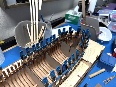
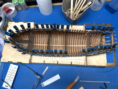
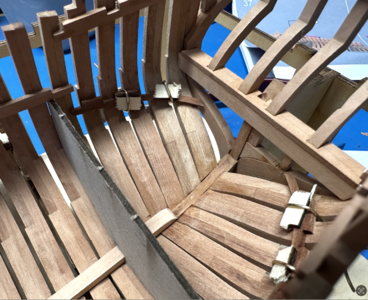
Hayling Hoy: POF kit [COMPLETED BUILD]

Thanks for all the likes, guys! It's very encouraging. I'm working hard on this one and hope to keep the progress coming.

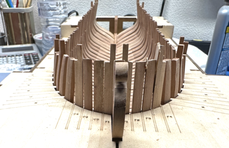
I'm still not getting the F5/furtherest out timber. The part after beveling isn't even close to a fit. Once again, I can see errors adding up, but this isn't even close and the building jig should have made up for some errors.

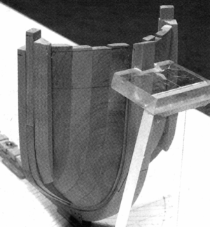
The results are sad. I also have David Antscherl's book on Hayling Hoy. I was originally thinking of trying a truly scratch build, but when the book opened up with no building board, keel, or frame contruction, and simply referring to the highly aspirational The Fully Framed Model series instead, I came back to reality. The construction of the two models is completely different, but it gives me some idea of what things should/could look like and some building tips. One gem I found is a way to handle that pesky last timber. The book points to not being able to handle and test fit that piece as it's shaped and applies it as partially shaped.
1693320230641.png
Sorry, didn't ask permission to use this one image, but hopefully they sell a few copies of the book because of this inclusion.
The piece is partially shaped and then attached. This way it can be shaped in place. With a building jig, I'll have to wait for a while to get this on there. I didn't see a step that attaches the wale before taking it out of the jig. Worse comes to worse, I can remove that section of the jig and get the piece on after the hull has been stabilized with the breast hook, clamps, and more.
I did cut myself a couple more pieces per. I'll try it the way it's implied to be done once more, but I have a plan if they just end up looking like junk.
 
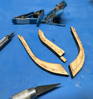
As I mentioned, the bollard timbers/ not-a-hawse pieces were, in fact, predictabily difficult and I had to rely on a little trial on error that would get better as a went along but may be catastrophic for the first pieces. Here's a few pieces rolling off the laser cutter (not really rolling, that would be nice though).
View attachment 392018
View attachment 392019
The top one is cut into leftovers from the frame redos. Along the top of that sheet are a whole bunch of shots at that external timber. I drove myself nuts trying to get that one right.

I'm a big believer in second chances. I am definitely punching below my weight for this project, so it helps with the unfortunate end of the learning curve. I'm spending a lot on wood though. I consider this a self led tutorial with great advice with the community here.
One thing I learned with the laser-cut frames is the tendency to clean up to the lines. For a next build I wouldn't go that far; sand it down to just before touching the lines. The excess still there can be removed once you start sanding the hull.
 
I hope you don't mind me mentioning it, but with my POF build it was critical to have the frames sitting properly on the keel ánd in the jig.
Bonding frames may lead to unintentional shift of the frame parts and the only reliable references you have are your keel and your jig.
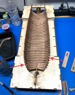
I saw in one of your pictures that a number of frames do not fit entirely in the designated notch. It might be worth some time to look into that and see it those small deviations might have a detrimental effect on your hull and potentially the rest of your build. I marked two locations with a red arrow, but I suspect there are some more:
IMG_0031.jpeg
 
Thanks for passing along all of your valuable experiences, good and bad, and your transparency about your trials and errors along with your creative approach. Very enlightening.Thumbsup
Seems like these kits, especially in wood (which is a very imprecise medium) are filled with hidden flaws and unforeseeable challenges, regardless of the source.

Pete
 
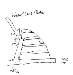
What's up with this part of the build. After shaping the timbers as beveled, F4, the second most outer timber, isn't close either. It suffers from the heel being too far aft. Here's a crude drawing.
1693320790128.png
Told you it was crude. The arrow points to where the heel extends past the half frame it is supposed to mate with. I triple checked, and this is the placement once you align the top of the timber to the rest and apply spacers between bow timbers to get the vertical close. I'm not sure what is going on.
I had to recut a couple of these because I goofed on one. Word of advice: always take the time to mark waste material onto your part with some Xs or scribbles, especially with the sharp bevels which look like an optical illusion if you look at them long enough. Lesson hard won
1693404269296.png
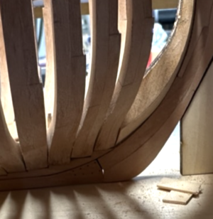
It is really a trial and error thing and the one I got to work looks like maybe not the best mate to the half frame, but I'm going to go with it. I just cut out more parts. Next, I go after the timber against the keel that I modified, the second F4, and attempt to get those little wedges in, although I am considering waiting until later in the build on that.
 
Last edited:
Thanks for passing along all of your valuable experiences, good and bad, and your transparency about your trials and errors along with your creative approach. Very enlightening.Thumbsup
Seems like these kits, especially in wood (which is a very imprecise medium) are filled with hidden flaws and unforeseeable challenges, regardless of the source.

Pete
Thanks Pete, great to hear and much appreciated!
 
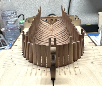
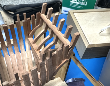
The bollard timbers and hawse pieces were a significant challenge. It took a lots and lots of shaping byond meeting the bevels scribed on the parts. I am super glad I scanned in the parts because I needed 2-3 attempts each. I have to admit, I almost gave up but there was something I found to be helpful. You have to fix the timbers as you go along to help test fit the next piece. I kept trying to do that with them all off the model, propping up multiple parts. In the end, I thought I was right and started glluing in pieces to find out I was wrong on the fourth piece. I had spent forever on it. But I cut a new copy, cleaned it up, and it didn't take nearly as much fussing to get it in right. In the future, I'll tack glue everything along the way. Lesson learned.
1693750740396.png
All the parts were spaced with 1/32" scrap top and bottom. Without the spacers, things moved around a bit.
The kit isn't set up for proper hawse pieces that mate to each other and have air spaces cut away and I needed a bit more order to the unruly timbers, so I used some of the scrap of 1/32" cherry on one of the laser cut sheets and made some spacers to simuklate. I wouldn't try to pass it off as the real thing, but it does give the bow a lot more symmetry and fairness. None of this will be visible in the final product, the wales and planking above will eventually be installed.
1693751160481.png
The only thing left with the bow timbers are the outboard most pieces, the little splinters. I have opted to install them once the frames are stabilized and I can take the model out of the jig. There's a good opportunity before planking.
 
On to the transom.
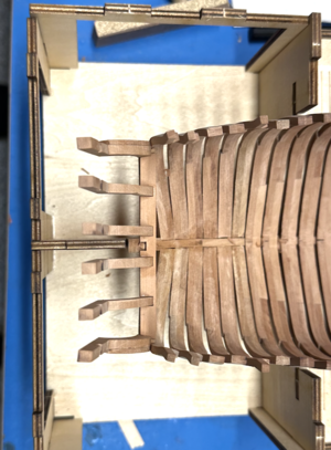
The instructions don't say it, but you need to remove the upper panels of the jig by the transom to work farther. Hope you didn't glue up!
1693751652850.png
The first pieces are pretty straight forward. The piece is bevels fore and aft, the slot is beveled, and the ends are tapered to allow the piece to span the last two aftmost frames. There is a place for it to sit on the sternpost, and it seats onto that notch well, but the notch does not come out flush to the piece. I tried. The thin piece on top is awesome. Such little effort to put in something that will make locating and attaching counter timbers so much easier!
1693751721485.png
 
I have to admit, I almost gave up but there was something I found to be helpful. You have to fix the timbers as you go along to help test fit the next piece. I kept trying to do that with them all off the model, propping up multiple parts. In the end, I thought I was right and started glluing in pieces to find out I was wrong on the fourth piece. I had spent forever on it.
I had to laugh when I read this part Glenn; I had the exact same experience. I wanted to get everything precisely right off the ship and then just glue everything in place. But that didn’t work for me (either). I ended up gluing in the most forward cant frame (with some temporary bracing in place) - then fitting and gluing in the bollard timbers - then hawse timber 1 - then hawse timber 2 - and so on. I have seen some very clever jigs being designed and used but that was beyond me so I just had to give it a go.

Enjoying your build…
Thanks Paul,
it looks like I'm in good company. Yes, setting the foremost half frames was the first big breakthrough, otherwise it was like some nightmarish nautical Jenga. I'm looking forward to trying again on another ship, but not too soon.
Thanks for checking this out, I know you've had your hands full with Kingfisher this year. Fantastic BTW.
Regards,
Glenn
 
The last three timbers on each side of the transom look pretty squirrely, but i'm having a hard time finding a reference to get it right. They seem to lean in too much, reversing the curve as you head aft. Not sure how I'm going to handle that. I just pulled a few of them off to make sure they are at least flush with the aft-most frame.
1693837793622.png
The instruction say to sand to shape after installing the cross member. I've saved all my shaping, including the sides of the cross member, until this stage. But those little timbers have me nervous on stability. There's going to have to be a lot of finesse in that area to withstand the rough sanding to shape needed. I'm going to wait until I've installed the clamp back there. That should give me better stability and also tell me if I'm on the same planet with the required alignment before I start doing heavy shaping.
All of this is going to be covered in the end, but, along with being a nice model, I'm seeing it as practice for more advanced ones. And maybe a scratch build some day. So details matter.
 
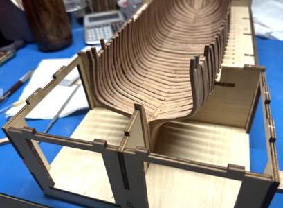
So, on to better supporting the frames. It was a delight to see the keelson in. It's hard to see here because I already put in the alignment guides, but I'll take a picture with the clamps later.
1693838149095.png
I have an issue and could also use some help with nomenclature. I tried to install the piece at the bow that looks like a breast hook but is installed much lower and I think was referred to as a stringer, although I'm not sure that's right. Wondering if anyone can let me know what that thing is called. But regardless of the taxonomy, you really can't install it when they instruct you too. There's no good way to gauge the proper height without the guides. In the diagrams and in external references, it looks like it lies in parallel to the lower clamps. There's also space for it in the alignment guides. I'm going to try to install it later, once more of the clamps are in. It shouldn't be blocked.
Another word on the installation of that piece. It is referred to as N20 in both the diagram and the written instructions. But N20 is actually one of the pillars for the capstan platform on the sheet. The piece in question is labelled M20 on the laser cut sheet. Also, definitely don't follow the bevel marked. From my best estimates, it's not close. I would do it once you've located it. For starters, though, you could probably bevel off half of it.

So if you know what the piece in question is, please let me know. And thanks so much for all the encouragement and likes, it's great to have support.
 
Happy Labor Day! Hope you got your fill from the grill.

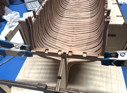
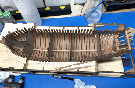
Today gave me a chance to get a little more done. I started the tricky work of putting in the deck clamps aided by lots of little blue clamps.
1693875069333.png
1693875117860.png
I started with the relatively easy ones at the top. Plenty of hot water for getting in the forecastle deck clamps.
Next, I had to get in the tricky one below the top deck. I had several ideas but in the end, wiring them worked the best. This is my first POF and I was excited that I actually could wire them in. There was a lot of turn to the fore and aft pieces below the main deck.
1693875331459.png
Once the wood takes shape, the quick PVC glue should do the trick. CA glue would be easier, but I'm not going to be shocked if I have to loosen them up and scooch (sp?) them around some in the end. The position is pretty tricky and there really isn't enough information in the plans to locate them properly. I'm wondering how others might do it. I tried to eyeball their relation to specific frames and heights on the guides, but it's pretty hazy. This will definitely be MY Hoy in the end.
 
Hi Glen, a really nice set up.

I read above that you have no plans in David's book, but according to Sea Watch Books there should be 3 sheets. I ask out of interest as I would like to buy the book and if it is without plans I will have to think about buying it.
 
I hope you don't mind me mentioning it, but with my POF build it was critical to have the frames sitting properly on the keel ánd in the jig.
Bonding frames may lead to unintentional shift of the frame parts and the only reliable references you have are your keel and your jig.
I saw in one of your pictures that a number of frames do not fit entirely in the designated notch. It might be worth some time to look into that and see it those small deviations might have a detrimental effect on your hull and potentially the rest of your build. I marked two locations with a red arrow, but I suspect there are some more:
View attachment 392034
I do think RDN1954 has got the point. It looks like almost each frame mismatches the berth. It's quite strange as my very same operation went remarkably smooth (but one of the first single frame - the n. 3 - I put together, resulted a little bit scarce in width) despite I simply trusted the scantling profiles, even ignoring the draw... . Rubberbands are the prompt and most suitable solution, anyway. Cheers
 
Hi Glen, a really nice set up.

I read above that you have no plans in David's book, but according to Sea Watch Books there should be 3 sheets. I ask out of interest as I would like to buy the book and if it is without plans I will have to think about buying it.
Thanks Tobias,

Yes there are plans with David Antscherl's book and they are splendid. I suppose I could have put them to better use locating those parts. I still need to build his fancy height/depth gauge. His book is good but you really need a volume or two from his series, The Fully Framed Model, if this is your first time around. He skips things in the new book and refers to the other work for more information. It is still extremely informative and, of course, inspiring to see that level of craftsmanship documented.

But you're right, I do have plans that I can reference, even if they didn't come with the kit.
 
Back
Top