- Joined
- Jul 27, 2021
- Messages
- 213
- Points
- 253

Bomb Vessel Granado Cross Section, Scale 1:72, POF Kit
by "Miniature Arts"
Description
HMS Granado was launched at Harwich in 1742, during the War of the Austrian Succession as a sloop-of-war. During this war she captured a French privateer. During the Seven Years' War she served both as a sloop and as a bomb vessel, and participated in naval operations off the coast of France and in the West Indies. When the Navy sold her in 1763 she became the mercantile Prince Frederick. Around 1775 she became the whaler Prudence, sailing in the British northern whale fishery. Around 1781 she became a government transport and was wrecked on 20 May 1782 on the coast of India.
Source: https://en.wikipedia.org/wiki/HMS_Granado_(1742)
The kit is based on an original design of Jeff Staudt and the MSB Forum: http://modelshipbuilder.com/e107_images/...sm1-48.pdf
Technical data
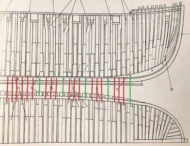
I was sent this nice little kit for a review (to read my review please check here: https://shipsofscale.com/sosforums/...on-scale-1-72-pof-kit-pearwood-version.12300/) and would now like to build it. I have started with a first frame, the keel and the corresponding jig.
It should be noted that the instructions, which are in Chinese, are absolutely inadequate. It is strongly recommended that you download the free plans from MSB (http://modelshipbuilder.com/e107_images/custom/bvcsm/bvcsm1-48.pdf) and study the building steps thoroughly.
It should also be noted that my kit was cut with a laser that was not super well adjusted. The so-called kerf is very large and requires consideration if you want to have beautiful joints It is certainly not a kit for a beginner and you need patience and calm.
I can also only advise you to practice on leftover pieces how best to remove the burn marks from the laser and then to do this thoroughly.
The first Frame


The Jig


Cheers
Dirk
by "Miniature Arts"
Description
HMS Granado was launched at Harwich in 1742, during the War of the Austrian Succession as a sloop-of-war. During this war she captured a French privateer. During the Seven Years' War she served both as a sloop and as a bomb vessel, and participated in naval operations off the coast of France and in the West Indies. When the Navy sold her in 1763 she became the mercantile Prince Frederick. Around 1775 she became the whaler Prudence, sailing in the British northern whale fishery. Around 1781 she became a government transport and was wrecked on 20 May 1782 on the coast of India.
Source: https://en.wikipedia.org/wiki/HMS_Granado_(1742)
The kit is based on an original design of Jeff Staudt and the MSB Forum: http://modelshipbuilder.com/e107_images/...sm1-48.pdf
Technical data
- Scale: 1:72
- Length Overall: 123.0 mm
- Height Overall: 90.0 mm
- Width Overall: 120.0 mm
- Level: Intermediate to Advanced
I was sent this nice little kit for a review (to read my review please check here: https://shipsofscale.com/sosforums/...on-scale-1-72-pof-kit-pearwood-version.12300/) and would now like to build it. I have started with a first frame, the keel and the corresponding jig.
It should be noted that the instructions, which are in Chinese, are absolutely inadequate. It is strongly recommended that you download the free plans from MSB (http://modelshipbuilder.com/e107_images/custom/bvcsm/bvcsm1-48.pdf) and study the building steps thoroughly.
It should also be noted that my kit was cut with a laser that was not super well adjusted. The so-called kerf is very large and requires consideration if you want to have beautiful joints It is certainly not a kit for a beginner and you need patience and calm.
I can also only advise you to practice on leftover pieces how best to remove the burn marks from the laser and then to do this thoroughly.
The first Frame


The Jig


Cheers
Dirk


