Good evening Peter. A one of a kind build. Wow. The complexity of this project at times makes me hold my breath for you, although you seem to have it completely under control. Amazing. Cheers GrantIt took some time to show you some progress again.
The frames to fix the mast tube and kossing have been placed:
View attachment 428458
These are the frames 33 to 38 and the watertight bulkhead 39.
With both parts apart:
View attachment 428424
The frames 33, 35 and 37 have a deck beam that connects the kossing and the stringer plates on the side of the deck.
The whole thing is already so sturdy that I no longer need the help of bracing here:
View attachment 428425
The deck round can be seen a little here. Also that the side profiles of the top of the kossing nicely follow the line of the top of the deck.
The deck round is better in view here:
View attachment 428426
You can also see the 1,5 dgr. offside of the kossing.
The underside receives even more attention. I'm not satisfied with that.
That will come later when I continue with the fish holds.
They are still very flexible lengthwise when it comes to the side curve of the frames. But the bilge beams will be added later at the height of the bilge.
Now I'm going back to the forecastle to build that up:
View attachment 428427
The space between these 2 parts will be filled. This port side part will therefore be fully furnished.
But first install all the frames and then spray paint.
Regards, Peter
You are using an out of date browser. It may not display this or other websites correctly.
You should upgrade or use an alternative browser.
You should upgrade or use an alternative browser.
BALDER, Vlaardingen Herring Lugger from 1912, scratch build scale 1:50 Plate-On-Frame
- Thread starter Peter Voogt
- Start date
- Watchers 40
Well Jim ……….you made me blush and a bit speechlessI am not sure what else I can add to the words of my colleagues. With the level of detail and overall complexity, you are doing as Ab said, a prachtig (Dutch) job, and your build is one (if not the only one) of the unique builds here. Bravo, mon ami!
Regards, Peter
Last edited:
You also thanks for this very nice words, Grant. Luckily I can still breathe, it’s sometimes more ……. Ggggrrr ……. come on, stay in place ……Good evening Peter. A one of a kind build. Wow. The complexity of this project at times makes me hold my breath for you, although you seem to have it completely under control. Amazing. Cheers Grant
Regard, Peter
Just an example of how I work and the preparations I make.
I will place frame 41 first. Because the water tank must be constructed between frame 41 and the watertight bulkhead 39:
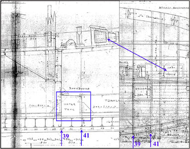
(Source: the old drawings of the aforementioned shipyard)
On the left is a drawing of the longitudinal section. I have shown the water tank with the blue frame.
On the right the corresponding part from the top view drawing.
However, it does not show how wide the water tank is.
For clarity, a double arrow has also been added at the conversion for access to the forecastle.
The top of the water tank is partly the floor of the forecastle where the galley with the stove is located in the middle.
There will be a 'lantern' in the deck above the stove, a hood with glass that can be opened.
There will be a drying area on either side of the galley with a hatch on the deck.
The longitudinal angle profiles run across the bottom of the water tank from bulkhead 51 to 39. From the fore side of the water tank, standing strips complete the angle profiles to the keelson. Just like from bulkhead 39 backwards.
Given the text of one of the two old specifications, I estimate that the water tank was made over the full width of the tweendeck, up to the skin plates.
And specifically states:
"On the sides, drain the necessary air pipes to the deck, ending under the railing with a folded end."
Before placing frame 41 I built in some extra 'safeguards':
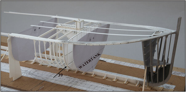
To support the already extended stringer plates, I had already printed the shape of frame 28 on thick paper using the Fushion 360 drawing of that frame.
Frame 41 is also printed out with guide lines for the bottom and top of the water tank.
From the forepeak I laid 2 strips of 3.2 x 0.25 mm to control the sheer over the deck beams. This strip will later be glued over the deck beams and form the sides of the shutters.
Based on the mold I can now build and install the frame and construct the water tank.
All in all, I spent a while studying drawings and reading the old specifications. To get an idea of all the items I have to take into account.
Regards, Peter
I will place frame 41 first. Because the water tank must be constructed between frame 41 and the watertight bulkhead 39:

(Source: the old drawings of the aforementioned shipyard)
On the left is a drawing of the longitudinal section. I have shown the water tank with the blue frame.
On the right the corresponding part from the top view drawing.
However, it does not show how wide the water tank is.
For clarity, a double arrow has also been added at the conversion for access to the forecastle.
The top of the water tank is partly the floor of the forecastle where the galley with the stove is located in the middle.
There will be a 'lantern' in the deck above the stove, a hood with glass that can be opened.
There will be a drying area on either side of the galley with a hatch on the deck.
The longitudinal angle profiles run across the bottom of the water tank from bulkhead 51 to 39. From the fore side of the water tank, standing strips complete the angle profiles to the keelson. Just like from bulkhead 39 backwards.
Given the text of one of the two old specifications, I estimate that the water tank was made over the full width of the tweendeck, up to the skin plates.
And specifically states:
"On the sides, drain the necessary air pipes to the deck, ending under the railing with a folded end."
Before placing frame 41 I built in some extra 'safeguards':

To support the already extended stringer plates, I had already printed the shape of frame 28 on thick paper using the Fushion 360 drawing of that frame.
Frame 41 is also printed out with guide lines for the bottom and top of the water tank.
From the forepeak I laid 2 strips of 3.2 x 0.25 mm to control the sheer over the deck beams. This strip will later be glued over the deck beams and form the sides of the shutters.
Based on the mold I can now build and install the frame and construct the water tank.
All in all, I spent a while studying drawings and reading the old specifications. To get an idea of all the items I have to take into account.
Regards, Peter
Last edited:
Thanks, Stephan. Indeed: step by step ........ and keep thinking.........See the next post.......Step by step and a lot of patience, you building something beautiful.
Regards, Peter
Last edited:
And again an "oh yes", you have to do that first........
Make the supports on bulkhead 39 to allow both halves to stand freely on the yard beam:
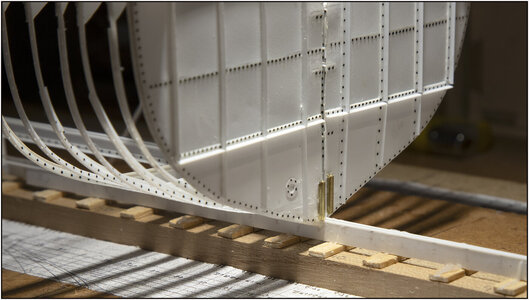
Brass bushings with an internal diameter of 1 mm are glued to the corners of both half-bulkheads. Mark a hole on the yard beam with a piece of 1 mm wire through the bushes.
Removed all side wedges that secured the keel plate to the yard beam shims.
Removed the starboard half of the yard beam:
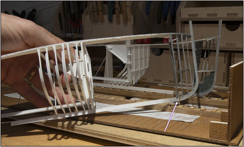
At the arrow the previously made pin and bushing on bulkhead 51.
Drilled out the hole for the 2nd pin and installed the pin:
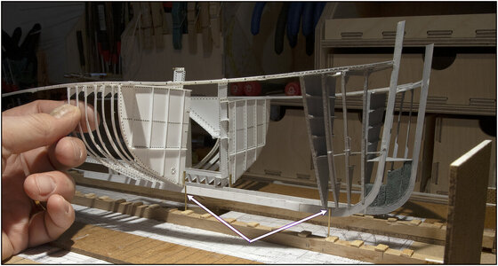
Also cleaned all shims on the yard beam and removed all old adhesive residue.
The starboard half on both pins:
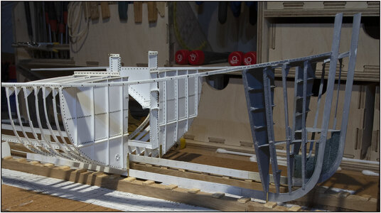
And now stands loose on the shims of the yard beam.
Also do the port side, then replace the wedges to secure the alignment of the keel and then I can continue.
Regards, Peter
Make the supports on bulkhead 39 to allow both halves to stand freely on the yard beam:

Brass bushings with an internal diameter of 1 mm are glued to the corners of both half-bulkheads. Mark a hole on the yard beam with a piece of 1 mm wire through the bushes.
Removed all side wedges that secured the keel plate to the yard beam shims.
Removed the starboard half of the yard beam:

At the arrow the previously made pin and bushing on bulkhead 51.
Drilled out the hole for the 2nd pin and installed the pin:

Also cleaned all shims on the yard beam and removed all old adhesive residue.
The starboard half on both pins:

And now stands loose on the shims of the yard beam.
Also do the port side, then replace the wedges to secure the alignment of the keel and then I can continue.
Regards, Peter
Last edited:
- Joined
- Oct 28, 2018
- Messages
- 661
- Points
- 403

Vakwerk Peter,
Hier niet eerder vertoond
groet
Henk
Hier niet eerder vertoond
groet
Henk
Thanks, Henk. Even if it concerns plastic.......Craftsmanship Peter,
Never shown here before
groet
Henk
Regards, Peter
Damn...she is fragile..., but gorgeous.
Damn...she is fragile..., but gorgeous.
Good evening Peter. The way you presented this post you make seem as simple as riding a bicycle (especially for you Dutch guys)And again an "oh yes", you have to do that first........
Make the supports on bulkhead 39 to allow both halves to stand freely on the yard beam:
View attachment 428716
Brass bushings with an internal diameter of 1 mm are glued to the corners of both half-bulkheads. Mark a hole on the yard beam with a piece of 1 mm wire through the bushes.
Removed all side wedges that secured the keel plate to the yard beam shims.
Removed the starboard half of the yard beam:
View attachment 428717
At the arrow the previously made pin and bushing on bulkhead 51.
Drilled out the hole for the 2nd pin and installed the pin:
View attachment 428718
Also cleaned all shims on the yard beam and removed all old adhesive residue.
The starboard half on both pins:
View attachment 428719
And now stands loose on the shims of the yard beam.
Also do the port side, then replace the wedges to secure the alignment of the keel and then I can continue.
Regards, Peter
 .
.Cheers Grant
Thanks, Grant. I do love cycling on my bikes. Well noticed similarity: 2 pins / 2 (pitch) axels …….Good evening Peter. The way you presented this post you make seem as simple as riding a bicycle (especially for you Dutch guys).
Cheers Grant
Regards, Peter
Last edited:
very interesting - looks so fragile - and I am pretty sure it is fragile
- Joined
- Jan 9, 2020
- Messages
- 10,378
- Points
- 938

I have to agree with my colleagues - the seeming fragility is also what strikes me. I can only imagine that makes the planning even more crucial as you have to incorporate checks and balances all the time. I agree with @Jimsky Jim that this must be one of the most unique builds witnessed on this forum; certainly as far as the medium goes and that is not even taking into account all the special details you are incorporating.
Thanks, Uwe. But Fragile ............. I'll have to show it to you somewhere in real life what the construction can have.very interesting - looks so fragile - and I am pretty sure it is fragile
Regards, Peter
You also thanks for this nice comment, Heinrich.I have to agree with my colleagues - the seeming fragility is also what strikes me. I can only imagine that makes the planning even more crucial as you have to incorporate checks and balances all the time. I agree with @Jimsky Jim that this must be one of the most unique builds witnessed on this forum; certainly as far as the medium goes and that is not even taking into account all the special details you are incorporating.
What can I say to that......... I personally don't think it is that unique, just scratch from drawings with a keel, keelson, frames, deck beams, etc. It is only entirely made of poly, but that is also becoming more done. ....... (I'm quite good at putting things into perspective.......
Regards, Peter
- Joined
- Jan 9, 2020
- Messages
- 10,378
- Points
- 938

Aaah - but remember - perspective is a matter of perception!(I'm quite good at putting things into perspective.......)
Started working on the design of the water tank.
First made an overlap drawing in Photoshop from the 3 old drawings:
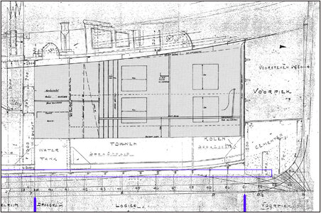
-At the bottom a strip of the old line drawing with the position of the frames.
-Above that the old cross-sectional drawing of the construction.
-In the middle the 'greyed' drawing of the layout of the forecastle as drawn for the Amsterdam restoration.
The positioning of the frames between 39 and 51 is slightly different on the old construction drawing than on the old line drawing. This may still be visible in the blue rectangular frame.
I'm keeping the one in the line drawing, because that's where I made the frames.
The new part of the combination drawing is glued on the construction floor.
First I installed 3 beams between the watertight bulkheads 39 and 51.
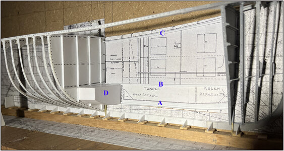
I made the photo tilted, with the starboard part on the construction floor. So the drawing is actually flat.
A is the keelson.
B is the center floor beam.
C is the center deck beam. The deck beams run over this beam.
D is the paper mold of the water tank.
Now actually standing. The starboard construction template is now level on the construction floor.
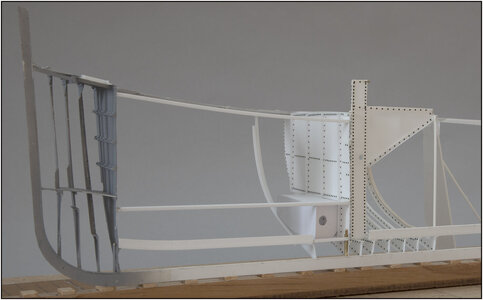
The frame 41 has been placed temporarily.
The swing shot can be seen in the tank. The opening in the corners and center allows water to flow through the entire tanks.
Now that this seems to be working, with a great deal of AL-FI, I can start making both parts of Evergreen's water tank.
Regards, Peter
First made an overlap drawing in Photoshop from the 3 old drawings:

-At the bottom a strip of the old line drawing with the position of the frames.
-Above that the old cross-sectional drawing of the construction.
-In the middle the 'greyed' drawing of the layout of the forecastle as drawn for the Amsterdam restoration.
The positioning of the frames between 39 and 51 is slightly different on the old construction drawing than on the old line drawing. This may still be visible in the blue rectangular frame.
I'm keeping the one in the line drawing, because that's where I made the frames.
The new part of the combination drawing is glued on the construction floor.
First I installed 3 beams between the watertight bulkheads 39 and 51.

I made the photo tilted, with the starboard part on the construction floor. So the drawing is actually flat.
A is the keelson.
B is the center floor beam.
C is the center deck beam. The deck beams run over this beam.
D is the paper mold of the water tank.
Now actually standing. The starboard construction template is now level on the construction floor.

The frame 41 has been placed temporarily.
The swing shot can be seen in the tank. The opening in the corners and center allows water to flow through the entire tanks.
Now that this seems to be working, with a great deal of AL-FI, I can start making both parts of Evergreen's water tank.
Regards, Peter
Last edited:
Good afternoon Peter….my SO
 . As always your detail is mind blowing. Awesome. It is starting to look like a skeleton of a ship-exciting. Cheers Grant
Good morning Peter. I always wait in anticipation for your posts, and then my mind goes..Started working on the design of the water tank.
First made an overlap drawing in Photoshop from the 3 old drawings:
View attachment 431359
-At the bottom a strip of the old line drawing with the position of the frames.
-Above that the old cross-sectional drawing of the construction.
-In the middle the 'greyed' drawing of the layout of the forecastle as drawn for the Amsterdam restoration.
The positioning of the frames between 39 and 51 is slightly different on the old construction drawing than on the old line drawing. This may still be visible in the blue rectangular frame.
I'm keeping the one in the line drawing, because that's where I made the frames.
The new part of the combination drawing is glued on the construction floor.
First I installed 3 beams between the watertight bulkheads 39 and 51.
View attachment 431360
I made the photo tilted, with the starboard part on the construction floor. So the drawing is actually flat.
A is the keelson.
B is the center floor beam.
C is the center deck beam. The deck beams run over this beam.
D is the paper mold of the water tank.
Now actually standing. The starboard construction template is now level on the construction floor.
View attachment 431361
The frame 41 has been placed temporarily.
The swing shot can be seen in the tank. The opening in the corners and center allows water to flow through the entire tanks.
Now that this seems to be working, with a great deal of AL-FI, I can start making both parts of Evergreen's water tank.
Regards,

