Another Hayling 1760 build

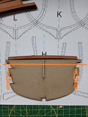
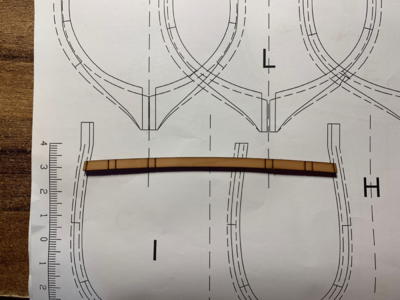
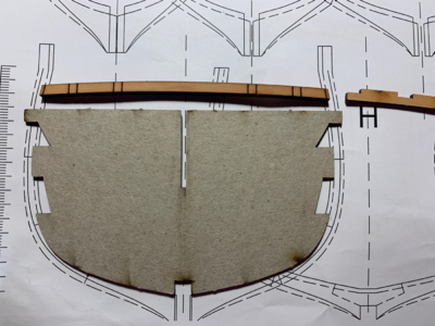
I've just sent Victor another email this time it's regarding the upper beams (N14 -N17) which appear to be too short as you can see by this photo of the frame plan showing the template used to measure the beam supports position and N14 which should span the width:
IMG_20221013_085512_091.jpg

I'm pretty sure it's not something I've done but we'll wait and see what he comes back with.

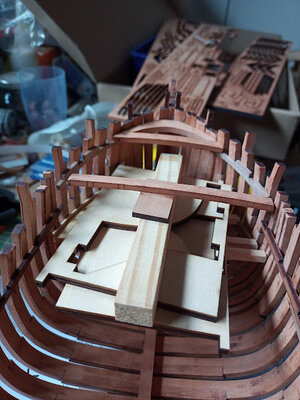
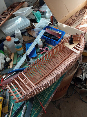
While I'm here, here's a shot of how it's looking so far. Please note that I've increased the galley deck length a bit and placed the stove to a where I think will be a more suitable place but I will need to cut a hole in the foredeck for the chimney:
IMG_20221012_134759_493.jpg

I really must do some tidying up of my bench and room soon Redface
Tom
 
I've just sent Victor another email this time it's regarding the upper beams (N14 -N17) which appear to be too short as you can see by this photo of the frame plan showing the template used to measure the beam supports position and N14 which should span the width:

View attachment 334074

I'm pretty sure it's not something I've done but we'll wait and see what he comes back with.

While I'm here, here's a shot of how it's looking so far. Please note that I've increased the galley deck length a bit and placed the stove to a where I think will be a more suitable place but I will need to cut a hole in the foredeck for the chimney:

View attachment 334076

I really must do some tidying up of my bench and room soon Redface
Tom
Hi Tom, in my opinion, you should center the template well on the drawing, try it

IMG_20221013_085512_091.jpg
 
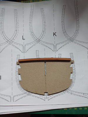
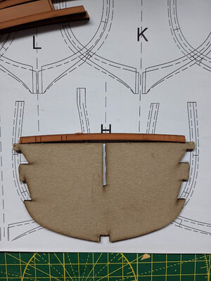
Following on from Frank's kind suggestion, I had a bit of an experiment. Here are 2 more photos. As I said..... very confusing.

Moving the template up to match the shape of the frame (which does perfectly if you ignore the keel cut out):

IMG_20221013_134421_858.jpg
But there is still a small gap between the frame and beam.

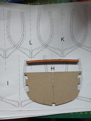
Where the beam needs to be to touch both sides of the frame:

IMG_20221013_134407_016.jpg

What ever the outcome, I would seriously suggest that only get this kit if you want real challenge.
 
Please check again.

On top of these templates is not the location of the beam by itself
With these templates the location of the clamps will be defined, and on top of these clamps (or better the recesses) the beams will be based.

niq9DqOO.png

With this knowledge the beam is slightly higher located
 
Following on from Frank's kind suggestion, I had a bit of an experiment. Here are 2 more photos. As I said..... very confusing.

Moving the template up to match the shape of the frame (which does perfectly if you ignore the keel cut out):

View attachment 334124
But there is still a small gap between the frame and beam.

Where the beam needs to be to touch both sides of the frame:

View attachment 334125

What ever the outcome, I would seriously suggest that only get this kit if you want real challenge.
I have no experience with Kit, I ask, is the template from that frame?
 
Please check again.

On top of these templates is not the location of the beam by itself
With these templates the location of the clamps will be defined, and on top of these clamps (or better the recesses) the beams will be based.

View attachment 334126

With this knowledge the beam is slightly higher located
If you expand the PDF frame to 200% (which I did when I fitted the supports) the supports rest on the template - so that's what I did. Also, my model looks EXACTLY right by the PDF rendering AND the prototype model build on this thread:
I really don't understand what's going on. :confused:
 
One last go at showing the problem. This is a close up of my model with scrap wood supporting the beam. You can see the gap on the left had side:

IMG_20221013_143444_149.jpg

I'm not really worried as to the final outcome because all this framing will be covered by the foredeck So any remedial work I do will be hidden and no-one (except me and you lot) will know it's there. :)
I just want to know what's gone wrong.
 
One last go at showing the problem. This is a close up of my model with scrap wood supporting the beam. You can see the gap on the left had side:

View attachment 334128

I'm not really worried as to the final outcome because all this framing will be covered by the foredeck So any remedial work I do will be hidden and no-one (except me and you lot) will know it's there. :)
I just want to know what's gone wrong.
prove that the dimensions of the details are correct and double-check them to scale only so you can have a confirmation where there is the anomaly
 
One last go at showing the problem. This is a close up of my model with scrap wood supporting the beam. You can see the gap on the left had side:

View attachment 334128

I'm not really worried as to the final outcome because all this framing will be covered by the foredeck So any remedial work I do will be hidden and no-one (except me and you lot) will know it's there. :)
I just want to know what's gone wrong.
Yeah it is kinda weird.
The frame that N16&N17 should be attaching to is I, if you place it onto the correct height, you'll find that it fits fine:
1665670467024.png
Would you mind maybe try place the ship back to the platform, and see if it can fit?
If it can, then i'll try to investigate what went wrong with my colleagues
 
prove that the dimensions of the details are correct and double-check them to scale only so you can have a confirmation where there is the anomaly
That's half the problem Frank - there are no dimensions mentioned anywhere in the instructions to refer to.
 
That's half the problem Frank - there are no dimensions mentioned anywhere in the instructions to refer to.
the model is not to scale? Did I get it right
  • Scala: 1:48
  • Lunghezza totale: 675,5 mm
  • Altezza complessiva: 653 mm
  • Larghezza complessiva: 341 mm
  • Larghezza dello scafo (solo): 135 mm
  • Lunghezza dello scafo (solo): 488 mm)
 
Last edited:
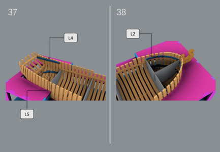
Also just to add, if you have a close look at the image showing the paper mould (step 38), you could find that the two ends have reached the outside end of the frames, so it is normal to have them longer than the beam, as the beams should fit the inside end.
1665671597308.png
 
Yeah it is kinda weird.
The frame that N16&N17 should be attaching to is I, if you place it onto the correct height, you'll find that it fits fine:
View attachment 334145
Would you mind maybe try place the ship back to the platform, and see if it can fit?
If it can, then i'll try to investigate what went wrong with my colleagues
You photo shows frame 'I' with the beam at the level that the template would place it if it's NOT sat over the false keel. I placed the template OVER the false keel. It should actually sit between H and I or are you saying it should be ON TOP of the frame base and forget the cut out?????
Tom
 
You photo shows frame 'I' with the beam at the level that the template would place it if it's NOT sat over the false keel. I placed the template OVER the false keel. It should actually sit between H and I or are you saying it should be ON TOP of the frame base and forget the cut out?????
Tom
The template have a slot at the bottom of it, and should be placed on the keelson, so you are right with that. But you see, on this image, i place the template on where it should be, add the height of the bottom end of L2, and it fits, just like the previous one i sent you.
1665673438811.png
 
Last edited:
Back
Top