Alvin Clark

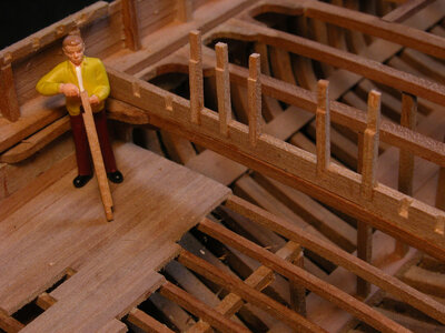
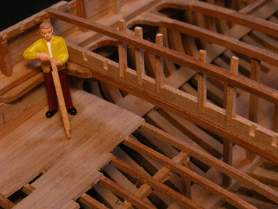
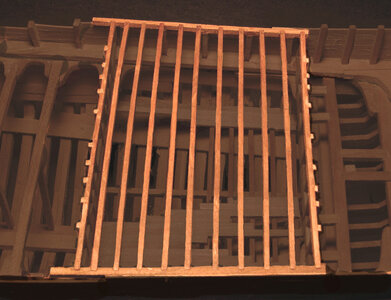
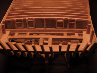
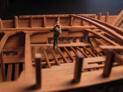
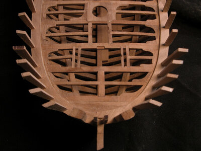
standing in the model taking a picture you would be taking a picture of the inside of the cabin, notice the knees at the corners of the cabin and the notches in the sill for the roof beams. The photographer seems to be supernatural and can float in air.
cabin shota.jpg

inside the Alvin clark.
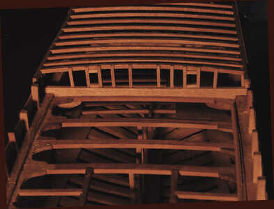
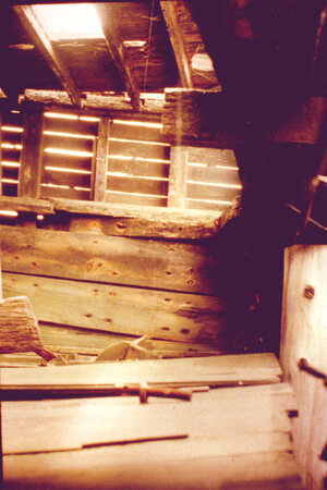
In this photo we can see the roof of the cabin and how the beams are mortised to the side timber. There were 5 planks of the side showing with the 6th and top plank running on the outside of the roof timber. The photo also shows the ceiling planking, the large knee between the deck beam and the side of the hull and the waterway, which is broken right before the arm of the knee.
At the time the photo was taken the Alvin Clark had suffered extensive damage and was about ready to collapse in on itself. The space between the side planking is the result of the hull drying out and the wood shrinking. Earlier photos show the planking tight without a gap.
A19a.jpg


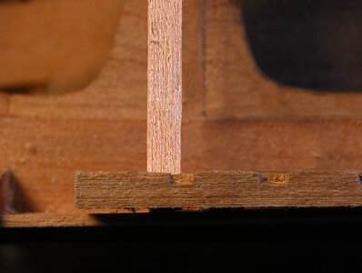
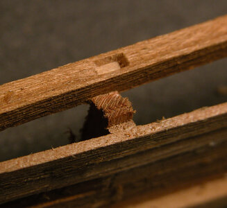
On the model the photo shows the mortis and the tenion joint used to secure the side timber to the tops of the stanchions. This will be one of those details never seen but it is there.
mortis teniona.jpg
 
Last edited:
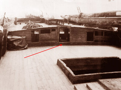
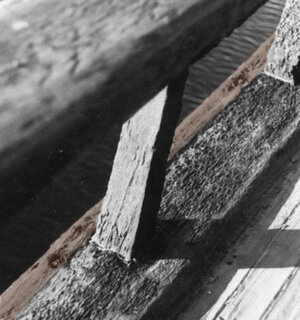
On deck looking aft at the front of the cabin you can see the sill pointed to by the red arrow, this is the next part to make. This is an archive photo taken long before i got to the Alvin Clark.

sill photoa.jpg
 
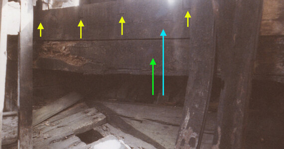
is looking at the sill from the inside of the cabin. The green arrow points to the deck beam and the blue arrow points to the sill. The sill was a large timber almost the size of a deck beam. The yellow arrows are pointing to the faint outline of the joints between the wall studs and the sill.

actual joinerya.jpg

Cutting the sills begins with laying out the shape on a piece of wood using electrical tape.
The bottom of the sill is cut to match the curve of the deck beam it will sit on. Notches for each wall stud is cut into the inside face of the sill and the ends are notched to fit over the waterway.

sill layouta.jpgfinished silla.jpg

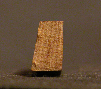
Looking at an end view of the sill youc can a taper on the outer face. Scraping a single edge razor blade back and forth along the face does this quite easy.

sill end viewa.jpg

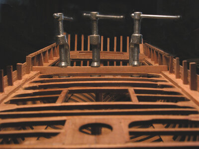
After the sills have been shaped and the stud notches are cut in, the next step is to place the sills in the hull. It is critical for the placement of the sill. Looking at the photo the sill is places half way through the roof beam notch. This is done so the inner face of the wall stud, when setting in its notch will lay against the outer face of the roof beam.

sill lineupa.jpg

The sill is glued and clamped to the deck beam. In the backround you can see the notches sill for the back wall in place.

clamped silla.jpg
 
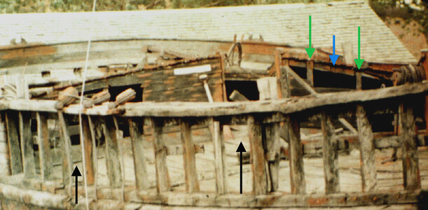
Looking at the forward wall we can see the green arrows are pointing to the wall studs. These studs are nailed to the outer face of the roof beam. The blue arrow points to a shallow inset for the wall stud. The two black arrows point to the sill.

actual forward walla.jpg

you can see how the wall studs are installed. The bottom of the stud is notched to fit the notch in the sill. with the top notch facing in.

studs2a.jpg

The top of the stud is notched for the roof beam. Each stud was left a little longer and the tops will be trimmed to the top of the roof beam once the wall is finished.

studsa.jpg
 
Last edited:
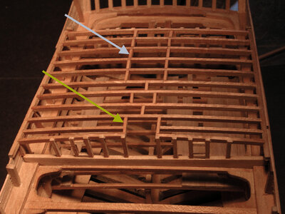
With all the roof beams put into place the next step is to add the blocking. Not only does the blocking create a solid footing for the skylight and companion way framing but it also adds considerable strength to the roof structure.

finished cabin roofa.jpg

Thewhite arrow is pointing to the blocking for the skylight and the yellow arrow is the blocking for the companion way. In deck construction the blocking would be the carlings. between the skylight and companion way blocking is added to stiffen up the roof structure.

blockinga.jpg
 
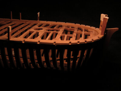
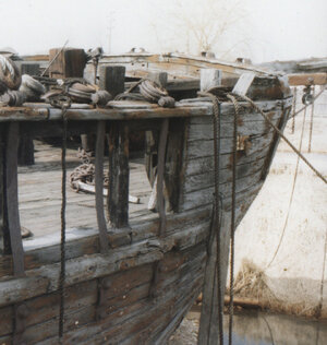
Having cut off all the stanchions at the bow iwill have to start from scratch and build the bulwarks. Looking at the photo you will notice the bulwark has a flare from the deck to the cap rail. When the stanchions were cut off the shape of the flare was lost. On war ship the bulwarks were built thick and heavy to protect the gun crews. The stanchions were part of the frames called the top timbers. On a merchant ship the bulwarks were built light, some of the stanchions on the Alvin Clark were part of the frame while others were separate timbers run down below the waterway and nailed to the sides of frames.

bow photoa.jpg

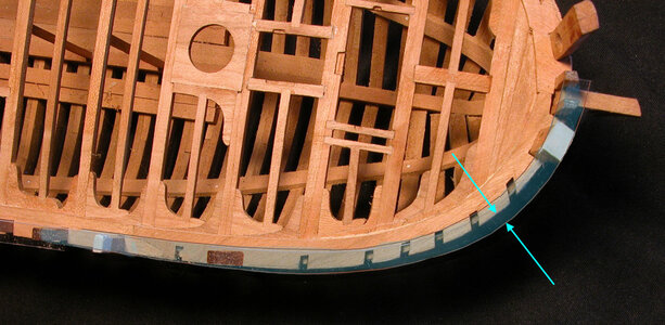
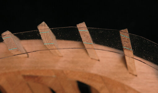
A trick to set the stanchions is to use the plastic found in product packaging, this is clear plastic molded around thousands of items. Shape of the cap rail is on the plans, i make a tracing and cut out the bow section of the cap rail. Using two-sided tape place a piece on the hawse timber and the first standing stanchion. Note the area shown by the blue arrows, this is the flare seen at a side view of the bow in the photo above. The flare begins at the hawse timbers, flares out as it rounds the bow then tumbles inward and meets the side of the hull. A reflection in the plastic gives an idea of what has to be accomplished. The stanchion blanks are set to fall under the plastic cap rail.

plastic rail1a.jpg

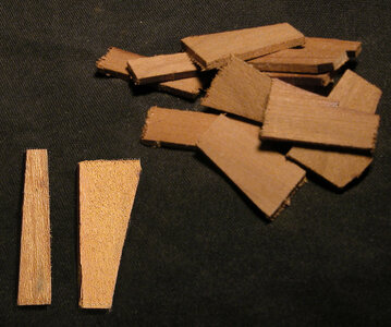
To begin, a bunch of blanks were cut from .100 thick scrap material. Blanks for the bow are larger than the final size because these are shaped with a bevel on the inside and outside edges. All the stanchions are made just a little bigger than the finish size of 5 x 5. The reason stanchions are made a little larger is because the tops must fall directly in the center of the cap rail. You can cut the stanchions exact size and fit them under a plastic template of the cap rail or trim them down once they are in place, either way works fine.

blanksa.jpg

With the stanchion blanks in place the exact size are marked with blue lines on the tops. On the actual ship the stanchions were 5 x 5 timbers 33 inches from the top of the waterway to the bottom of the cap rail.

marks1a.jpg
 
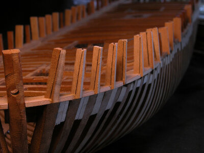
When the bow stanchions are glued in place the bevel is marked on the outer edge. With all the bow stanchions on the hull it is better to sand them all at once. This gives a better flow from stanchion to stanchion as apposed to shaping each stanchion and then gluing them to the hull.

stanchion2a.jpg

Stanchions were left oversized to take up any slight errors in positioning them on the hull and any minor dips or bumps in the lines of the hull.

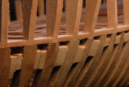
Continue to sand the stanchions all along the hull until the stanchions are flush with the edge of the waterway. At this point blend in the bulwark stanchions to the hull. Any over sizing of the stanchions after the final hull sanding will be taken off on the inside of the stanchion.

stanchion4a.jpgstanchion3a.jpg
 
Bottom photo is an underside view of the waterway at the bow as fitted. You can see the oversized waterway sticking out beyond the hull framing. To the right is the same shot after the waterway has been sanded and shaped to the hull.

untrimmed waterwaya.jpg

the same shot after the waterway has been sanded and shaped to the hull.

stanchion5a.jpg

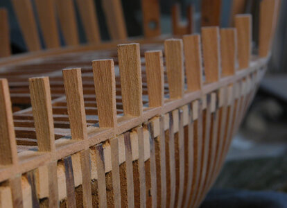
A top view of the bow stanchions in place. The flare of the bulwark can be seen. The inside bevel still has to be done.

stanchion6a.jpg
 
Planking the bulwarks is a straight forward operation. The planks were one-inch thick tongue and grove oak nailed to the stanchions. It’s a question for the model shipwrights to show the fasteners or not. Some builders will use wooden treenails while other will not show any fasteners. If done wrong the fasteners will rune a otherwise perfect model job by covering the model in little dots.

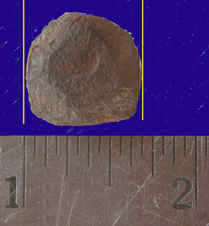
Below is an actual planking spike from the wreck of the Alvin Clark, on a 1:48 scale the spike would be a 1/8 inch long and have a head of .012. for the bulwarks a little smaller spike was used.

real spikea.jpg
Looking at the head of the larger spike we can see it was 5/8 round being slightly mushroomed out from being hammered. These spikes were used for the hull planking and decking, the smaller spikes were used for the bulwarks. A six inch spike would have gone right through the planking and the stanchion with its point sticking out of the other side. The smaller spikes look exactly the same as the larger ones except they were 4 inch long and with a little over a 3/8 head. Trying to simulate this on a 1:48 scale model using wooden pegs would be very difficult and the peg itself would be so small its ability to actually hold anything is questionable.

actual spike heada.jpg

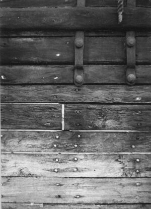
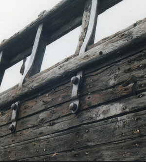
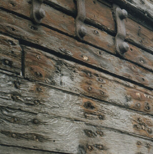
Below are photos of the actual planking showing the spikes, if you look very close you can see the difference in size of the spikes used for the bulwarks and hull planking. Directly left of the metal fastener in the first photo there is a small spike, comparing it to the lower spikes you can see a difference.

real spikes2a.jpgreal spikes1a.jpg

The spiking pattern is clearly shown, the spikes were in pairs at every frame. One spike was nailed to each half of the frame. The photo was taken months before the wreck was bulldozed and trucked to a land fill. At this point the wood dried out and shrunk most was dry rotted. This is why the surface of the planks look so rough.

real spikes3a.jpg
 
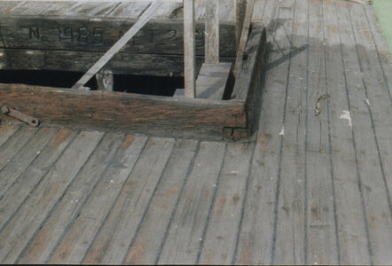
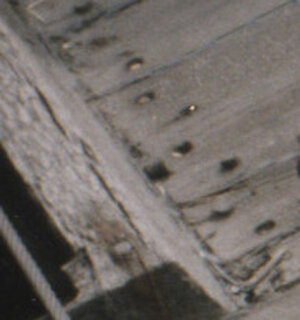
Nailing down the deck planks were different than the hull and bulwarks even though the same six inch spikes were used. Many models show dark dots and black caulking between white colored planks. In reality as you can see in the photo below it is hard to see a fastener, the caulking is light gray, the deck itself is a weathered gray color and not the stark white some model builders portray.

deck viewa.jpg

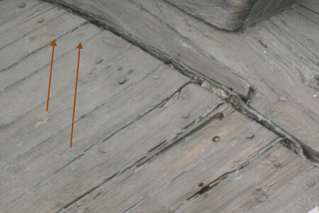
Even looking close at the fasteners being pointed to by the red arrows it is very difficult to see them. There are two fasteners at the point of the first arrow and one at the second arrow.

deck plugs1a.jpg

In the very close up photo we can see why the fasteners are so hard to see. They were countersunk and a plug was put over the head of the spike blending them into the decking.

deck plugs2a.jpg

Depending on the reason the model is build will determine the use of fasteners. If the model is built to show its construction and the methods of how it is built the builder will find a suitable way to show the spikes. But if the model were built to portray a sense of realism the fasteners would not be visible at 1:48 scale.
 
The photo demonstrated the size of fasteners on a 1:48 scale model. The top larger dots are the size of the tiny brass nails available at hobby supply stores. They measure .025 with the heads cut off. The bottom two dots are very close to the actual scale size.

dot sizea.jpg

In the photo below are the actual tiny brass nails. It is clear to see oversize fasteners tend to overpower the model. If the entire side of the model were fastened with oversize nails or wooden pegs it would be very distracting. If the fastener can not be done to scale it is better left off or simulated. The scale simulated spikes were made with a T pin and a hole was poked into the plank. Glue was mixed with black paint and wiped over the holes. Thin silver, copper or brass wire can be used in a pre drilled hole if you want to drill the required 350 holes for the bulwark planking. Bamboo or a close-grained hardwood can be drawn through a draw plate down to .013, styrene plastic rods are also available.

brass and pinsa.jpg

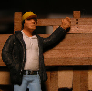
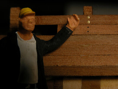
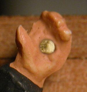
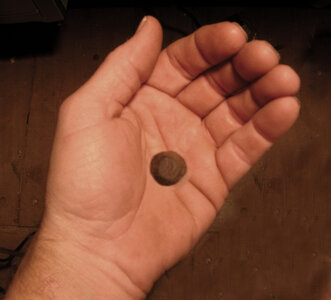
The two photos of hands are an interesting size comparison in scale. The plastic figure is holding a brass nail with the head cut off from a hobby supply. Looking at your own hand you get the idea how big and out of scale a tiny brass nail would be,it is almost the size of the palm of your hand. The real hand is holding an actual scale spike head. You can see how small the real spike head is.

plam2a.jpgpalm1a.jpg
 
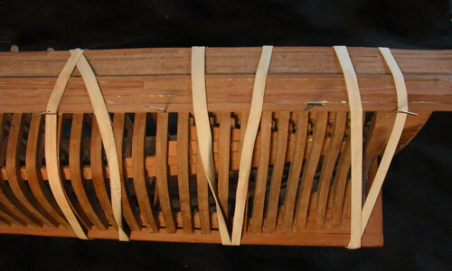
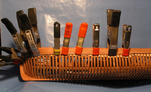
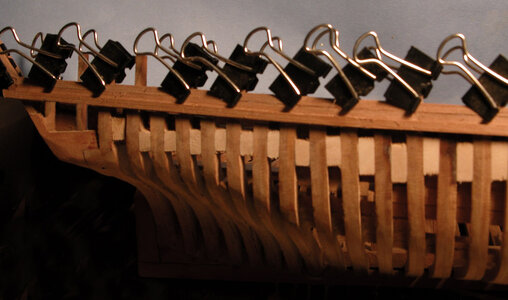
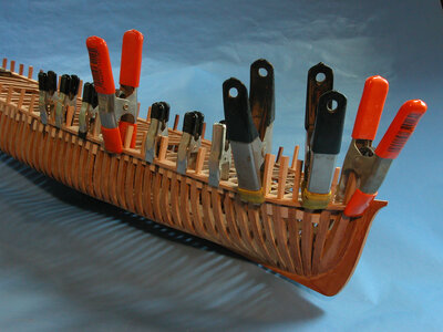
There are several ways to plank the hull. One method is to use a CA instant glue. Using this type of glue wont require all the clamping, just hold the plank for a few seconds and it will stay in place. Another glue is 5 minute epoxy once again all that is required is to hold the plank until the glue grabs and holds. The last method is the use of Titebond wood glue, which requires a 30 minute clamping time. Using this wood glue one must have a collection of clamps. Clamps are only good to the point of the deck level, below that you can’t reach the hull planking with a clamp. Rubber bands will do the trick for holding planking where a clamp will not reach. Make sure you hull is strong enough to take the pressure of the rubber bands or you will end up crushing the hull or bulwarks.
pmbandsa.jpgpmclampa.jpgclamping planksa.jpg
 
Last edited:
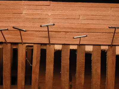
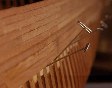
The use of T pins work surprising well if used correctly. When the plank is glued to the hull use a T pin tight to the edge of the plank and press it into the frame, the next pin push into the frame at a steep angle as shown in the second photo. This angle will hold the plank tight to the frame surface. Alternate the pins one straight in the next at an angle.

pmtpina.jpgpmtpin2a.jpg
 
Last edited:
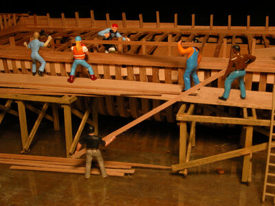
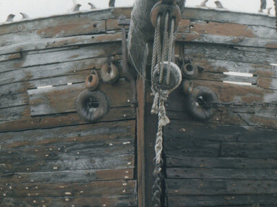
Before the planking can be put on the bulwarks at the bow there are two pieces which must be made and fit to the hull. These are thick large planks where the hawse rings go through.

actual bowa.jpg

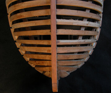
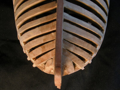
Over the years in model building it became acceptable that all ship hulls had a rabbit cut along the keel and stem where the planks fit into. An interesting fact about the hull planking on the Alvin Clark is there was no rabbit cut in the stem or along the keel. The planking butted against the stem and caulked.
 
The use of T pins work surprising well if used correctly. When the plank is glued to the hull use a T pin tight to the edge of the plank and press it into the frame, the next pin push into the frame at a steep angle as shown in the second photo. This angle will hold the plank tight to the frame surface. Alternate the pins one straight in the next at an angle.

View attachment 421850View attachment 421849
Dave, I am not a big fan of those pins as the plank holders, and actually, I am not a fan at all. While pushing the plank with the pin, it (the pin) will leave dents, and it won't be easy to repair. Alternatively, you can use a scrap of wood to push the plank, and then 'pin' the scrap instead of the actual plank, IMHO.
 
Dave, I am not a big fan of those pins as the plank holders, and actually, I am not a fan at all. While pushing the plank with the pin, it (the pin) will leave dents, and it won't be easy to repair. Alternatively, you can use a scrap of wood to push the plank, and then 'pin' the scrap instead of the actual plank, IMHO.

i totally agree and they should NOT be used if planking with a softer wood like Basswood, Cypress or Alaskan Cedar your right it will leave a dent in the wood you can not sand out. i should mention i am using Applewood for the planking which is much harder and the pins only left tiny indents plus the thinkness of the planks were thicker than the finish so the tiny marks left by the pins sanded away.

You bring up a good point in model building and that is what works for one model may not work for another or a methed used by a builder should not be considered "the way it should be done"
 
Last edited:
Back
Top