Alvin Clark

in order to start the build i need a plan
there are two ways to approach a plank on frame build one is to use the frame blank method which is very accurate because you are not assembling individual frame pieces, the frame is cut out as one unit.
see the process here as rick builds the Fredrick from frame blanks


my plan is to break down all the frames and laser cut them, while i was add it i also broke down the deck into deck beams, ledges, waterways and knees, then the keel assembly. each frame is color coded so i know what part goes to what frame. The pros and cons to the different methods of frame construction building a frame blank and cutting out the frames as one unit has the advantage of knowing the shape of the frame is correct. Building up each frame from per cut parts introduces an element of assemby error, the parts are cut close to the finish size so any miss alinement of one piece compounds the error to the pieces that attach to it.
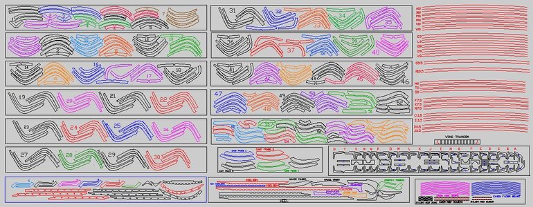
laser parts.JPG
 
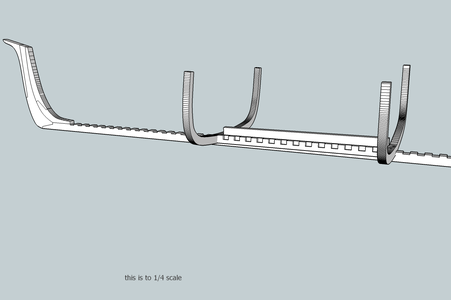
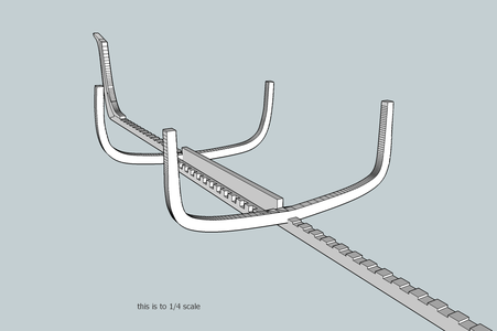
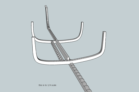
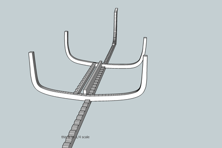
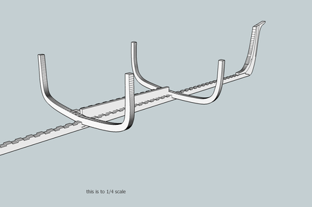
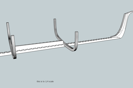
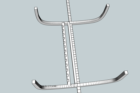
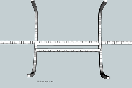
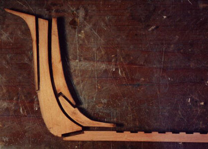
lets look at the keel structure before we begin The A.C. had a main keel and a secondary keel which formed the base of the center board box.

keel1.pngkeel2.pngkeel3.pngkeel4.pngkeel5.pngkeel6.pngkeel7.pngkeel8.pngkeel9.pngkeel10.png


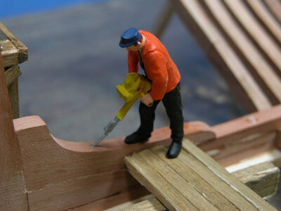
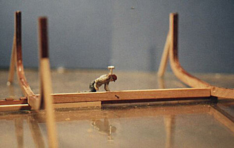
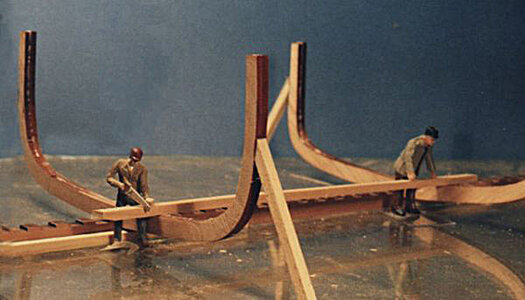
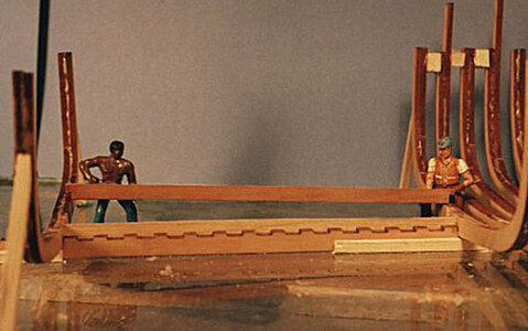
As i created the stage sets i would i send photos to Harold and he would send back comments. Every now and then we would get together and talk. I said i never kept up with fine carving never had the time to practice. Figures out of the 1840 don't exist and i can't carve them, So my idea was not to recreate the 1840s but use a modern day crew to reconstruct the ship there are thousands of these figures out there. For years i collected the little people from garage sales and rummage sale, church sales things like that. I thought this is not the fine art of Harold's carvings so i asked him about plastic people v/s fine carved figures in boxwood he said they are the same because its the sudden impact, how you created it is not the point. Harold told me that only some of his little people are the master carvings. He made a mold of the original and cast it in this slow setting resin. It starts out like a gummy bear or taffy and you can stretch it, squeeze it down, bend the arms and legs. As the resin hardens he would sculpt in the finer details. If you want a crew find figures on line and warm them up and re-sculpt them.


Once the keel pieces have been cleaned its time to join the two sections.

18a1.jpg


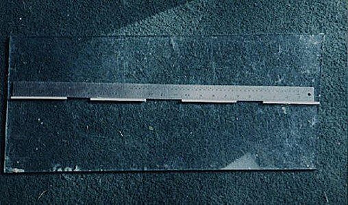
The only thing to watch for is to be sure the two sections are joined so that the keel is straight from end to end. Two shorter keel sections are less likely to warp as opposed to one long keel. the keel was placed flat on the work table and against the straight edge of the ¼ inch plate glass, then the scarf was glued together.

9718a2.jpg

Using some sort of fasteners is totally up to the builder. Some builders will rely on the glue alone, while other builders will use an additional fastener. Traditionally in model ship building bamboo or a hardwood is pulled through a series of holes until the right diameter is reached. An alternative to the tedious job of making treenails is to use brass, copper or silver wire. In areas that will not show I use styrene plastic rods available in diameters from .010 on up in increments of .005. For the scarf in the keel I used a .040 styrene plastic rod dipped in 5-minute epoxy, the styrene rod is far stronger than wood. In actual ship building copper or iron rods were used clinched on the ends with rings.

9718a3.jpg
 
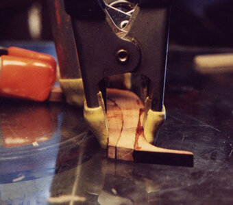
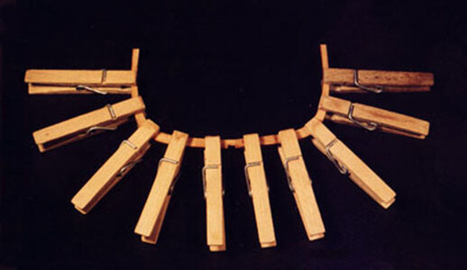
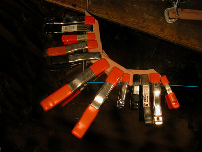
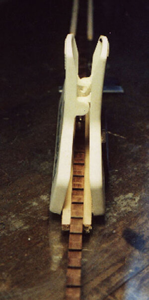
When the two pieces of the keel have been joined and pinned, the stem pieces are attached to the keel. This operation is best done with all the pieces laying on a flat surface to insure their alignment. Spring clamps are used to hold the pieces together.

9718a4.jpg
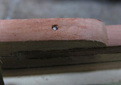
It’s up to the builder whether or not to pin the pieces once the glue has set up. On this model .040 styrene rods were used to hold the stem and deadwood pieces together. A correct size hole is drilled

k6.jpg

the pin is inserted into the hole

k5.jpg

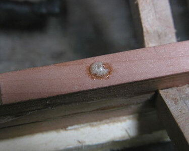
the glue being used Gorilla glue that expands so it bubbles up and fills the hole.

k8.jpg

a quick and light sanding evens out the top.

k9.jpg
 
Now comes the decision of how to build the model, a jig would be the safe way and the jig itself will hold the hull in place preventing any distortions. Considering wood will move regardless of how dry it is or how it was stored. You can take a piece of milled wood kept in a climate controlled shop and as long as it is there it will be stable. Take that piece of wood out of the environment and it will adjust itself to stabilize with the new environment. In the case of the A.C. project it is all about the little people and the building of a ship. A jig just did not fit into the theme of the build. So like walking the high wire without a net the A.C. was built upright without a jig.
 
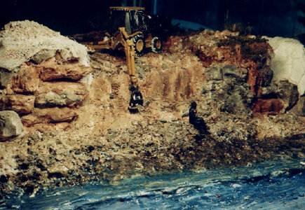
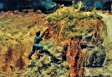
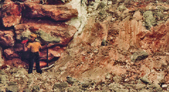
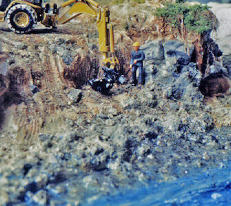
i had an idea for the project based on the work Harold Hahn did with his colonial shipyard diorama. That is to show the Alvin Clark on the slipways being built. so i stated to clear a plot of land next to the lake to construct the slipway.then add the keel blocks etc.

the following picture were taked with a 35mm film camera so the quality is poor. but you get the idea of what is going on.

c4a.jpg

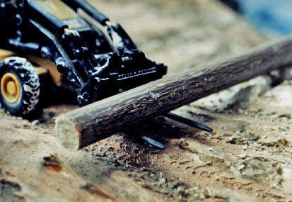
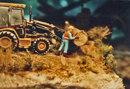
Clearing the lot is the first order of business

c3a.jpgc13a.jpg

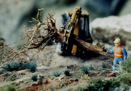
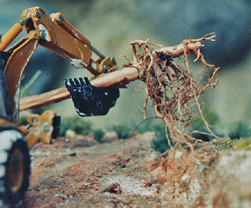
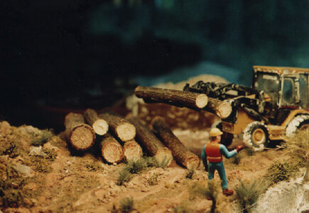
all the logs will be needed to build the slipway

c2a.jpg

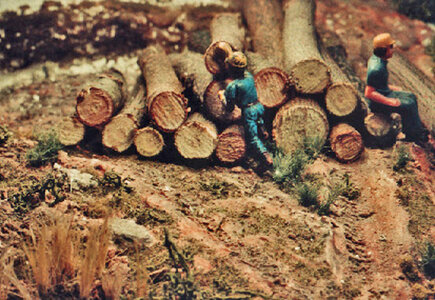
All the saw logs are stacked and waiting for the saw mill to be set up

c5a.jpgc6a.jpg

Even though there are some nice size logs none of it can be used to build the Alvin Clark because the wood is green and will rot very fast if used in the construction of the ship. It was a common practice to use green wood in ship construction as long as the space between the frames were packed with salt. The salt slowed down the rotting. Using salt the builder would install salt stops which were boards between the frames to prevent the salt from falling to the bottom and the bilge water metling the salt.
The Alvin Clark will not be using green lumber.

c8a.jpg
 
Last edited:
the slipway has to slant to the water so cutting down the shore line is started

c7a.jpg

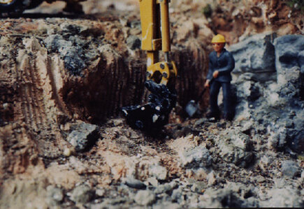
There are a few big rocks in the way here

c9a.jpg

ok boss we might have to blast there out but first i need a break a can of energy drink first.

c10a.jpg
c15a.jpgc16a.jpg

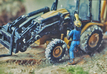
lets get a bulldozer in here to push some of this towards the water.

c12a.jpg
 
i ran this idea past Harold the next time we met. He thought it was a bad idea far to ambitious. It would work if the build was static but the idea was a progression of a build and to do that you need to rip apart the diorama at every stage and rebuild it. The idea of a slipway was scrapped and the build was changes to a piece of 1/4 inch plate glass. To build a hull you need a surface that will stay flat.
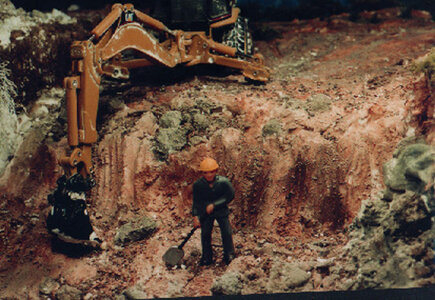
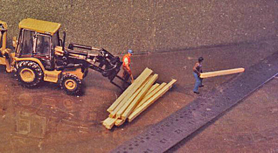
So the lot and slipway was abandoned and the guys cut up the logs into 6x6 timbers and brought them to the glass build site.

19718a6.jpg

a steel ruler was used as a straight edge and the timbers were glued to the glass.

19718a7.jpg

next the keel was set against the glued down timbers and a second set of timbers were glued to the other side of the keel. This pinched the keel between the timbers locking it in place

19718a8.jpg

the stern post and deadwood was set on the keel and at the bow the stem pieces were assembles on the flat surface and clamped together.

19718a5.jpg

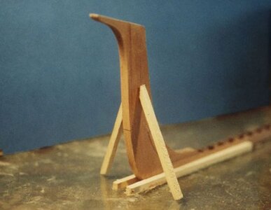
when the glue dried the sterm was set up right and braced

c2.jpg

that's it the keel is secured and now it is time to assemble frames.
 
I like this. It’s a fun approach to modeling - a sort of “living” diorama. You, know - there’s undoubtedly a book idea in there, if you plan to continue photographing construction vignettes that show how a modern crew would approach the various tasks of assembling a wooden hull.

That was an issue in the planning stages getting little people in the time period of 1840s and the methods used in a shipyard. Like Harold did here


The Alvin Clark as you said is a modern day approach to construction of a wooden ship. Harold did a snap shot of a colonial yard frozed in time.

a little side story
back many years ago i worked in an ad agency at one of the early computer graphic stations. We saved all our work on tape and processing time was very slow. Back then computers did not have the speed as todays so there was a lot of down time waiting to process. Along side me was a talented artist who could sculpt clay figures and objects. So we has chunks of modeling clay by our work stations and i would sculpt a figure and pass it on to her and she would add to it and slow but sure we had a tiny village, over time the village would be in a constant state of change. One day our boss said "clean up this mess" but at the time we had a client sitting with us making changes to his project. He said Bill i could have called in the changes but i came here to see the tiny village. Lo and behold the village became an attraction to our clients. a living creative claymation. That little village was a sort of inspiration to the Alvin Clark build.
 
in the land of the little people a frame would be assembled on a stage, a movable platform built across the keel. Each frame part was cut from a pattern made in the mold loft and transfered to the correct size timber. Each piece is then set in place and wooden pegs driven into pre drilled holes. In the case of the model styrene plastic rods are used. The entire Alvin Clark used iron rods and spikes except for the assembly of the frames. The frame has an iron rod through the keelson the floor timbers and into the keel. I was told wooden pegs were used to assemble the frames because the builders did not want to hit an iron rod when planking the hull or adding clamps and knees. If by chance they hit a wooden peg they could drive the spike home, if they hit iron they had to pull out the spike and deal with a hole.

T19718.jpg

Depending on the glue you use and how flat the frame pieces are you can use light clamping to hold the frame together.

5.jpg

There is a chance the frame pieces might have a slight warp and gluing them and clamping the pieces together you may not pull out the warp. But a slight warp may not matter in a hull with enough space between the frames. To be sure the frame is flat using stronger clamps and clamping the frame to a flat surface like a piece of plate glass will insure the frame is flat.

pc2.jpg
 
Very nice to see these photos. Everyone lending a hand. 1/2 to the foot, nice build scale. Dave, you have many years building and sharing. Thank you for all you have contributed to this hobby.

Very nice to see these photos. Everyone lending a hand. 1/2 to the foot, nice build scale. Dave, you have many years building and sharing. Thank you for all you have contributed to this hobby.

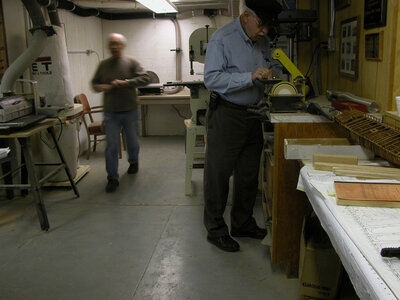
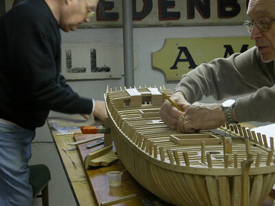
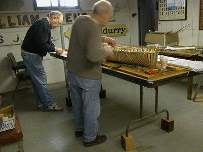
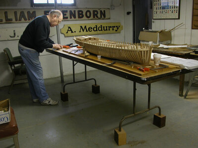
At it's peek the club had 90 some members the model club and museum hosted a yearly model show with a room full of models with builders from Erie PA to Chicago. Some of the members were Robert Bruckshaw who was building models for the Smithsonian and Harold Hahn. The museum had a model gallery where members could put their models up for sale and a full model shop.

shop6.jpg

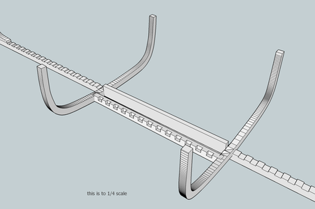
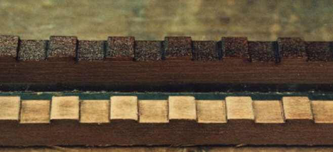
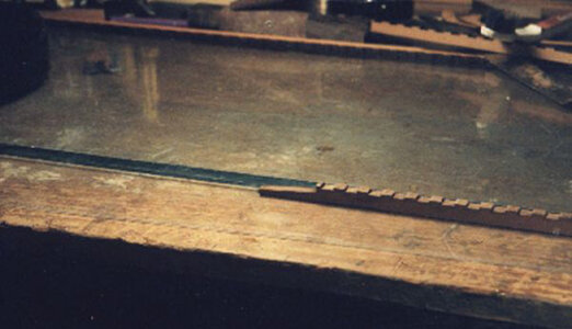
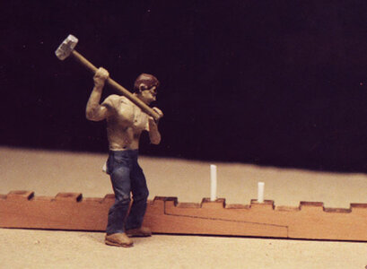
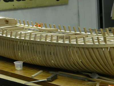
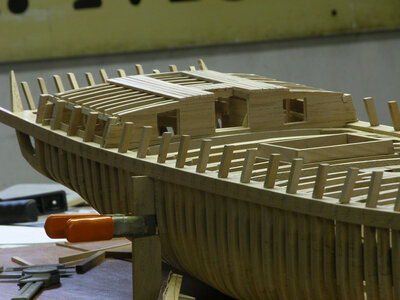
The Alvin Clark was a museum project with all the members working on it, the detail was right down to the joinery like the original ship with the hook scarf in the waterway.

shop1.jpg

The Alvin Clark project was in the last years of the club as members got older and older and less and less were showing up at meetings. Finally it got to a point there were only a handful of active members left. It was a big concern in the hobby of model ship building that there were no new, young members. The average age of members were 60 and above.

More pictures of the Alvin Clark under construction 25 years ago.

shop2.jpgshop3.jpgshop4.jpgshop5.jpgshop7.jpg

The model club died of old age there were no young model builders to pass on the knowledge of model ship building. When the museum moved to it's new location in Toledo the shop was not included as there were only 3 people left to man it.
 
i must say working in a large scale is so nice the parts are big and you get the feeling of woodworking as you cut sand and fit joinery.

so back to the little people and the building of the Alvin Clark

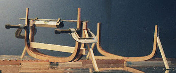
frames 18 and 32 are the key frames to set up first these are the full frames at the ends of the center board box. The frames between these are all half frames.
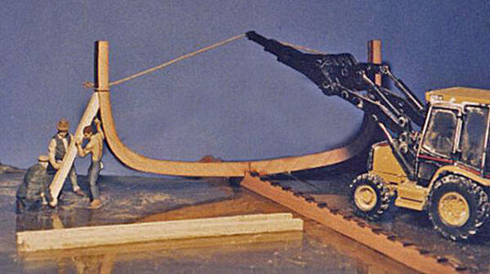
Lucky for us we have a crane to hoist the frame in place while it is being secured.

18a8.jpg


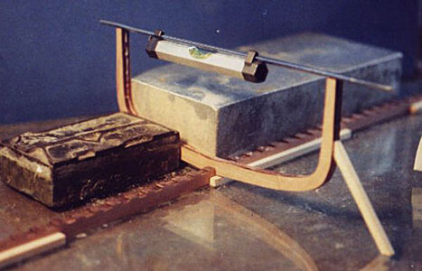
in the world of model building it is another story. It is important these two frames are placed square to the keel. What i am doing here is using a square block and running the long side along the keel. a block is then used to push and hold the frame to the end face of the long block. Braces are glued to the frame and glass to hold it in place.

18a9.jpg

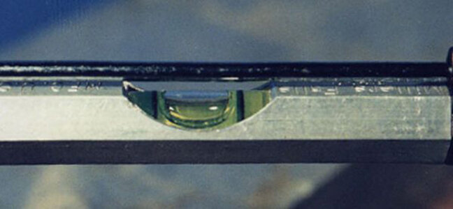
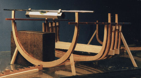
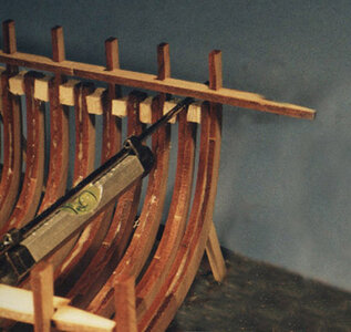
not only does the frame have to be square to the keel but also level from side to side so a line level sitting on a piece of heavy guage wire to check level

18a11.jpg
 
once frames 18 and 32 are set up the first timber of the center board box is spiked to the side of the keel. this timber is set to line up with the bottoms of the floor timbers.

18a12.jpg

for the other side of the box a notched keel timber is cut and set up.

18a14.jpg

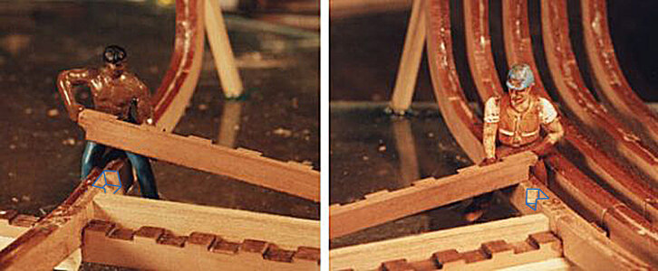
fitting the secondary keel. personally in my younger days i did loging and moving a timber that big would be extremely heavy for two men to handle. The weight of an Oak timber that size is in the range of 2,400 pounds. Setting the stage you do wonder how these heavy timbers were handled.

18a13.jpg

the ends of the keel timber are set into a notch in the frames outlines in blue.

18a15.jpg
 
Last edited:
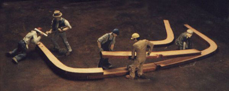
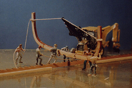
Setting up frames on an actual ships hull would require hoisting a massive Oak structure then holding it in place while its secured. The crew in the picture does have the aid of a back hoe with a crane and it still requires 6 men to seat the frame in its keel notch.

C1a.jpg

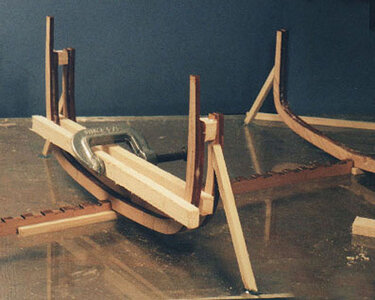
Once we have the two full frames set in place, square and level we are now going to build off them. The next frame to set up is frame 17. Frame 17 has a top timber which fits through a notch in the waterway. Care must be taken not to set the frame in backwards. The top timbers are on the forward side of the frames. Towards the bottom of the frame a timber is used between the frames and at the top spacer blocks are glued between the frames. This set up insures the frame space is the same distance at the top and bottom between the two frames. A simple C clamp hold the frames together, again a level is used to level the frame from left to right. No timbers are used to hold the frame to the glass surface.
E1a.jpg

With frame 17 glued in place a second spacer timber is held against the forward face of the frame. Getting ready for frame 16

E3a.jpg

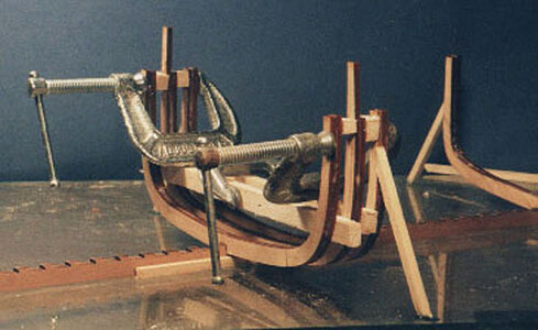
Frame 16 is a simple matter of gluing and clamping it to frame 17 with spacer blocks at the top..

E4a.jpg


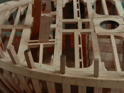
Frame 15 has its top timber fitting into the waterway notch. There will be a slight difference in the frame spacing so it is not a good idea to rely on just spacer blocks. The waterway is temporarily set in place with the top timber of frame 17 set in the notch. Fitting frame 15, spacers are used but this time the top timber is set into its notch. Clamping frame 15 is not necessary because the notch holds the frame in place.

E5a.jpg

This is a close up of the top timbers fitting into the waterway notches.

E7a.jpg

The idea is setting up the frames against the last frame in the hull. After 4 frames are set up check to make sure the last frame is level, square to the keel and at a 90 degree to the glass making sure the frame is not leaning forward or backward.
 
Last edited:
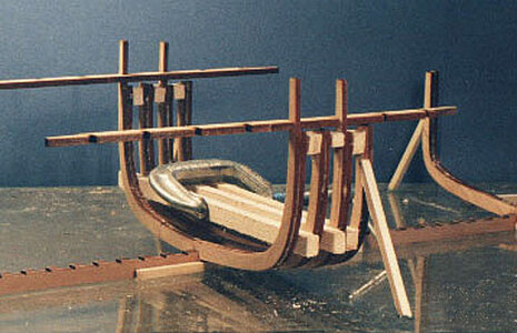
Before i continue with the framing of the Alvin Clark i am taking a break and posting a mini tutorial on hull framing. This will give you an idea of what exactly i was trying to do with the Alvin Clark.

Building a hull in some sort of jig was first introduced by Robert Bruckshaw and refined by Harold Hahn and is now the standard for plank on frame hull construction in various configurations. The original concept was called the upside down method and got good as well as bad reviews. Some actually made fun of the method saying that is not how a ship is built and Hahn resented the term "upside down building" he thought the comparison to actual ship building was ridiculous as this is a model.
Building a hull in a jig is definitely an advantage as apposed to building free form.

squareup.jpg

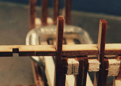
Another method is using spacer or filler blocks between the top timbers of the frames. This was actually done in ship building to create a soldid wall of timber to withstand cannon fire.
spaced frames.jpg
 
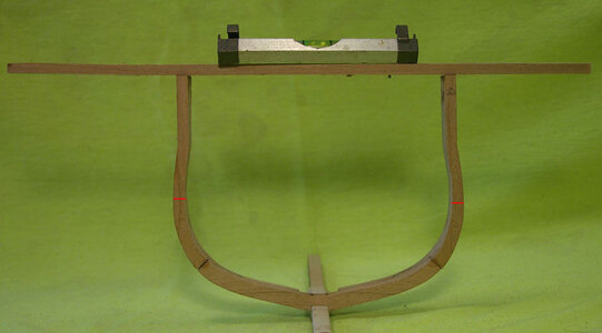
first is making sure the frames are level from side to side which can be done with a line level and a piece of wood sitting across the top. The only concern is to make sure the frame is cut out correctly so both top timbers are the same. Or mark the deck line or wale location (red lines) then you can clamp a stringer across the frame to level it.

level frame.jpg

another is to watch for a leaning frame

leaning frame.jpg

if one frame leans forward or back and your using spacer blocks all the frame will lean so it is best to check your frames every 5 or so.

spacer slant.jpg

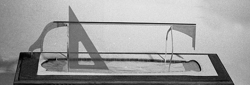
the last direction is keeping frames square to the keel. This may not show up along the hull until you reach the bow and stern and realize one side of the hull is different from the other and adding cant frames or half frames becomes a problem.

square frames.jpg

frames that are out of alinement will produce a distorted hull. Looking down the hull the frames should flow one into the other. Some builders will cut the frame a little larger leaving enough material on each frame to sand out any misalinement.

tilt frame side.jpg
 
Last edited:
Geting back to the build the idea is to use the notched waterway as a floating jig to locate the top timbers.

Rather than set frames one after the another, frames 14 to 10 were skipped over and frame 9 was set up. This was done to stabilize the waterway so it can be used to position the other frames. On frame 9 timbers were used to hold the frame in place to insure there will be no twisting of the hull. Frame 9 is free standing so a square block was used to square it with the keel and keep it from leaning fore or aft, the level is also used to keep the right to left level in check. Once again go through the check list level side to side and square to the keel in this case tframe 9 will set plumb as long as frame 14 is plumb and in its notch frame 9 will fall in place.

E8a.jpg

After frame 9 was set in place frames 10 to 14 were set in the keel notches and every other frame top timber is set in the waterway notches
and spacer blocks glued in. This now brings the framing to the forward end of the waterway.

F1a.jpg
 
Back
Top