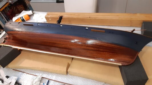
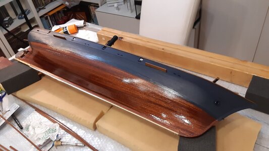
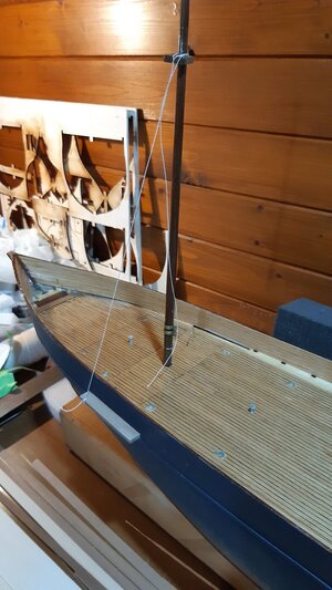
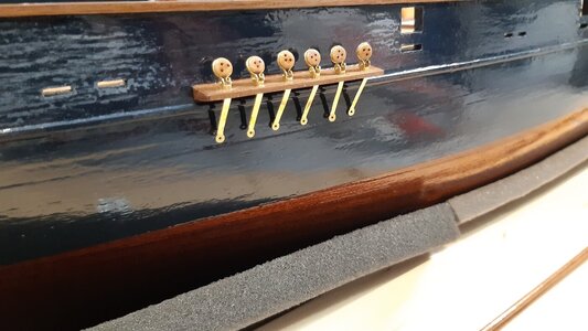
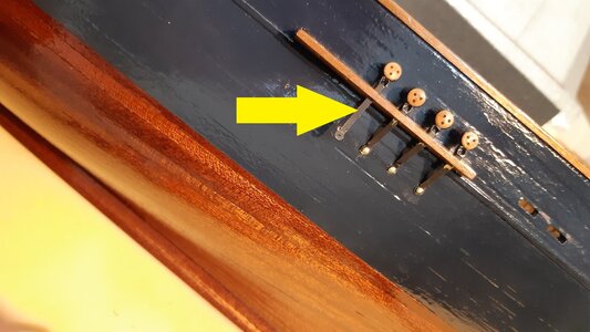
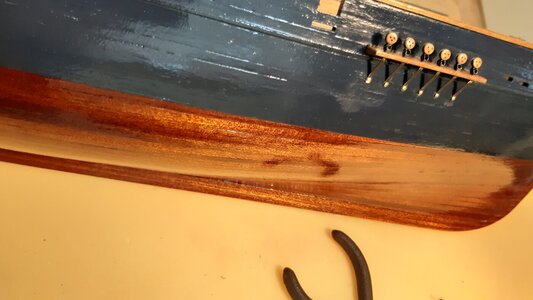
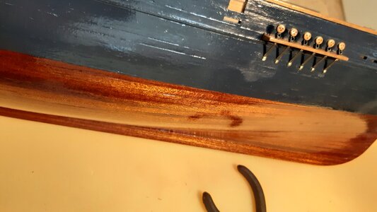
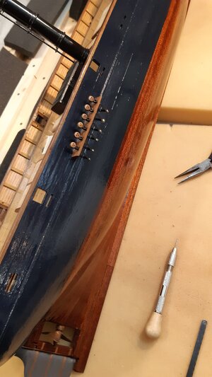
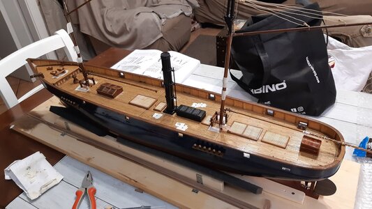
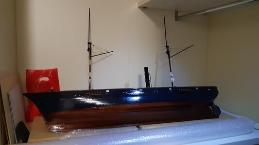
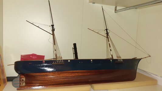
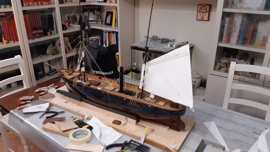
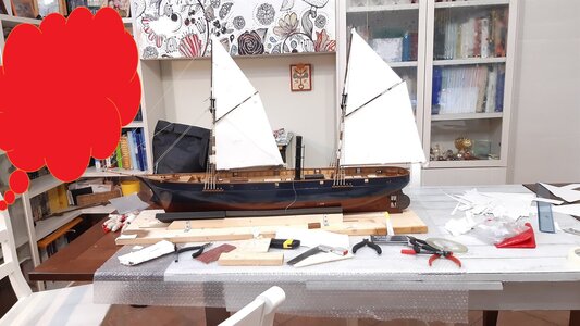
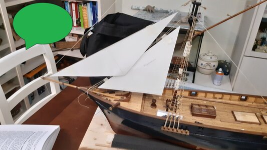
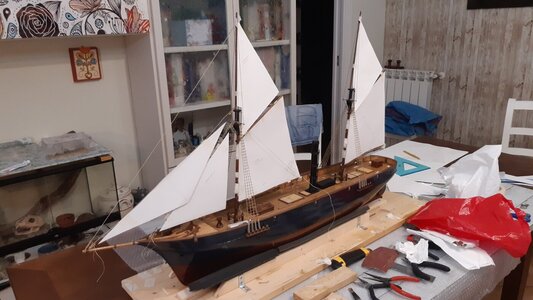
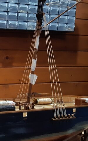
1/60 scale RC model of a schooner, loosely based on a gunboat steamship from the second half of the 19th century.

Ciao a tutti i modellisti RC navali.
Piccolo passo indietro.

Quello che vi mostrerò nelle foto seguenti è il metodo che ho utilizzato per abbassare il più possibile il baricentro del modello.
I test in acqua che ho effettuato man mano che la costruzione procedeva mi hanno fatto capire che non avevo più molto margine.
La zavorra che avrei potuto aggiungere non era molta. Sicuramente non più di 450 grammi.

In generale, 5 kg di dislocamento sono pochissimi per un modello lungo più di un metro che deve manovrare sei vele con due winch.
Un centimetro sopra o sotto la linea di galleggiamento per i modelli di peso pari o superiore a 7 kg non ha molta importanza.
Non importa quasi nulla se non devono navigare a vela. Un centimetro in meno sul bordo libero del mio modello è una tragedia.
L'unico asso nella manica era la sostituzione delle batterie. Se avessi sbagliato qualcosa e quindi il peso complessivo fosse stato maggiore di quello autoimposto, avrei sostituito le due batterie AGM al piombo con altre tecnologie più leggere, recuperando fino a 700-800 grammi.
Per fortuna avevo sistemato molto bene la posizione delle batterie, del motore e di tutte le altre parti essenziali.
Senza zavorra il modello ha reagito con una leggera spinta raddrizzante alle forze che lo sbilanciavano lateralmente.
Nonostante la spinta non fosse forte si stava comunque raddrizzando e quindi sono partito da una buona base.
Avrei dovuto aggiungere zavorra per aumentare la spinta raddrizzante in previsione di sbandamento molto forte nelle navigazioni al traverso con vento forte. (vedi foto allegata delle velocità di navigazione)-

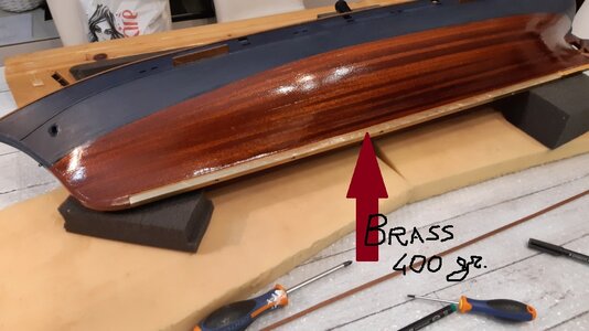
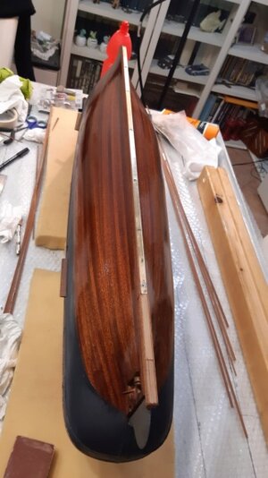
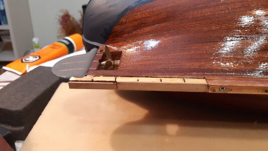
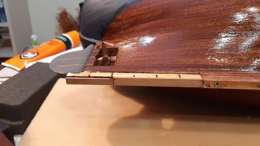
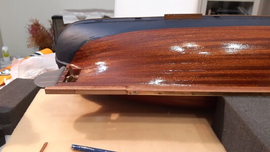
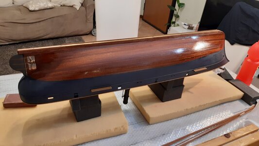
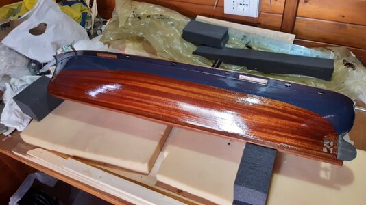
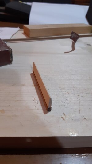
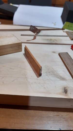
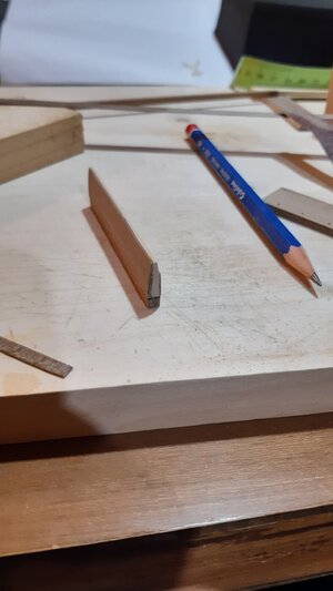
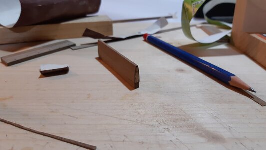
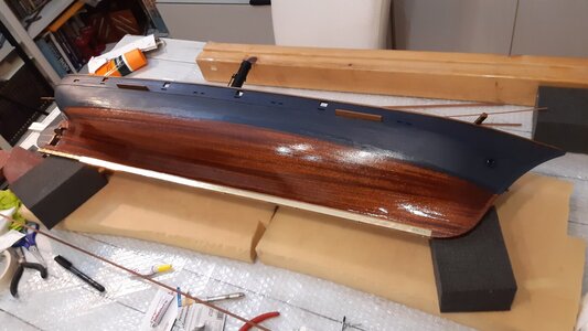
Il trucco è stato quello di sostituire la chiglia di legno con un prisma di ottone.
La riduzione, necessaria per poterlo rivestire meglio di mogano, ha interessato due dei quattro lati del prisma.
Originariamente la barra di ottone lunga 658 mm era 9x9 mm con la riduzione è diventata 8x9 mm.
Quello originale aveva un peso di 440 g. e la forza raddrizzante (non calcolata) era quella visibile nel filmato dedicato alla stabilità, il cui link è già stato inserito in questo topic.
Quello attuale pesa meno, siamo a 400 grammi. Non ci sono zavorre oltre a questa barra di ottone.

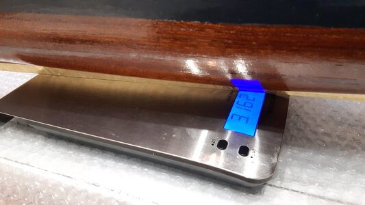
A quel punto dei lavori l'intero modello pesava 3162 grammi, a cui vanno aggiunti 1400 grammi delle due batterie e 90 grammi di elementi pronti da aggiungere per un totale non definitivo di 4652 grammi.

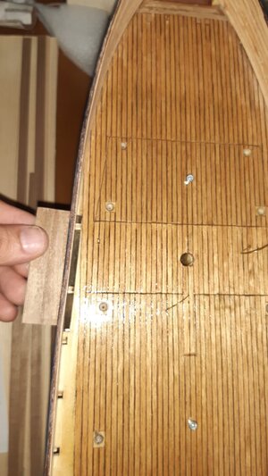
La barra di ottone viene avvitata allo scafo e ulteriormente bloccata con un finissimo strato di silicone.
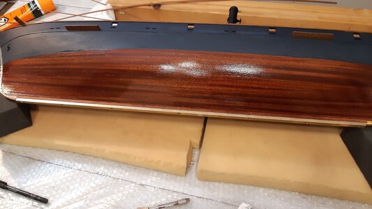
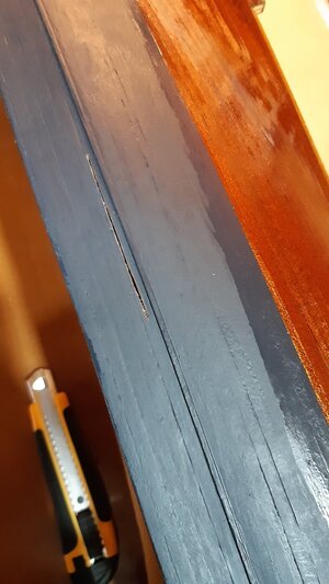
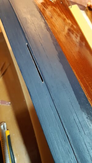
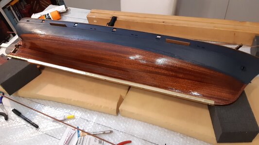
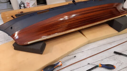
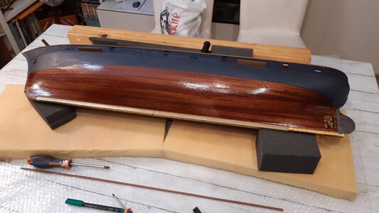
La barra di ottone non è visibile né lateralmente né dal basso, perché è completamente rivestita da listelli di mogano.
Oltre ad una questione estetica, il mogano verniciato impermeabilizza la barra di ottone.

Perché ho scelto l'ottone?
L'ottone è una lega che pesa più del ferro ma meno del piombo.
Rispetto al ferro/acciaio è migliore sotto ogni punto di vista tranne quello del costo.
Infatti non arrugginisce come il ferro, pesa di più ed è facilmente lavorabile. In commercio si trovano profili in ottone molto diritti.
Rispetto al piombo è meno pesante ma molto più lavorabile, inoltre non si trovano profili di piombo quadrati così lunghi e diritti (almeno in Italia).

Meglio ancora, più pesante dell'ottone, dell'acciaio e del piombo, sarebbe stato l'oro, ma 400 grammi d'oro mi sarebbero costati troppo! ahahahahahah.


Hello to all naval RC modelers.

Small step back.

What I will show in the following photos is the method I used to lower the model's center of gravity as much as possible.

The water tests I carried out as the construction progressed made it clear to me that I no longer had much margin.
The ballast I could have added wasn't much. Definitely no more than 450 grams.

In general, 5 kg of displacement is very little for a model more than one meter long that must control six sails with two winches.
A centimeter above or below the waterline for models weighing 7 kg and above does not matter much.
It matters almost nothing if they don't have to sail with sails.
One centimeter less on the free edge of my model is a tragedy.
The only trick up the sleeve was replacing the batteries.
If I had done something wrong and therefore the total weight would have been greater than the self-imposed one, I would have replaced the two AGM lead batteries with other lighter technologies, recovering up to 700-800 grams.

Luckily I had arranged the position of the batteries, motor and all the other essential parts very well.
Without ballast the model reacted with a slight righting push to the forces that unbalanced it to the side.
Although the push wasn't strong it was still straightening and therefore I started from a good base.
I should have added ballast in order to increase the righting thrust in anticipation of very strong heelings in Beam Reach sailings in strong winds. (see attached photo of sailing speeds)

The trick was to replace the wooden keel with a brass prism.

The reduction, necessary to be able to veneer it better with mahogany, involved two of the four sides of the prism.
Originally the 658 mm long brass bar was 9x9 mm with the reduction it became 8x9 mm.
The original one had a weight of 440 g. and the straightening force (not calculated) was the one visible in the film dedicated to stability, the link to which has already been inserted in this post.

The current one weighs less, we are at 400 grams.
There are no ballasts other than this brass bar.

At that point of the work, the whole model weighed 3162 grams, to which must be added 1400 grams of the two batteries and 90 grams of elements ready to be added for a non-definitive total of 4652 grams.

The brass bar is screwed to the hull and further blocked with a very fine layer of silicone.
The brass bar is not visible either from the side or below, because it is completely covered with mahogany strips.
In addition to an aesthetic issue, the painted mahogany waterproofs the brass bar.

Why did I choose brass?

Brass is an alloy that weighs more than iron but less than lead.
Compared to iron/steel it is better from every point of view except cost.
In fact it does not rust like iron, it weighs more and is easily workable. Very straight brass profiles are found on the market.
Compared to lead it is less heavy but much more workable, furthermore you cannot find such long and straight square lead profiles (at least in Italy).

Best of all, heavier than brass, steel and lead, would have been gold but 400 grams of gold would have cost me too much! ahahahahahaha.
20210925_204621.jpg

20210925_204617.jpg

20210922_225657.jpg

20210922_225652.jpg

20210917.jpg

20210920.jpg

20210922_230602.jpg

20210925_203048.jpg

20210925_205943.jpg

20210925_211226.jpg

20210925_225927.jpg

20210925_225929.jpg

20210925_232903.jpg

20210925_235859.jpg

20210919.jpg
 
This is one fabulous model! A RC with museum quality detail! th
Grazie mille Peter.

Anch'io ho qualche difficoltà talvolta con i messaggi (solo quando uso il cellulare e non il pc).

Ti ringrazio del complimento, tuttavia la qualità potrebbe competere con alcuni modelli RC ma non con quelli statici che ho visto in questo forum.
Voi avete un livello di accuratezza più alto.

Alcuni dettagli del mio modello mi soddisfano, altri proprio no.

Ad esempio, i tagli netti sul deck per l'apertura dei coperchi non sono riuscito a nasconderli bene.

Thanks so much Peter.


I too have some difficulties sometimes with messages (only when I use my cell phone and not the PC).


Thank you for the compliment, however the quality could compete with some RC models but not with the static ones I have seen in this forum.

You have a higher level of accuracy.


Some details of my model satisfy me, others I really don't.


For example, I couldn't hide the clear cuts on the deck for opening the lids well.
 
Nice work on the ballast!
I do have a question though; you don't appear planning on a (removable?) keel to lower the COG and to provide more area below the surface to counteract the forces of the sails. I have seen RC models with rather large removable keels, so I am wondering if you can get away with your solution, or that you will experience negatively effected sailing properties?

Ciao Johan.
Ti ringrazio e ti rispondo con molto piacere.

La mia intenzione è di non usare false chiglie sporgenti (anche se fossero rimovibili).

Quando ho disegnato per la prima volta lo scafo e ho immaginato il tipo di nave non c'erano molti video per farmi da guida.
Alcuni youtuber bravissimi (ad esempio "formerparatruper" ) che seguo ancora oggi nelle loro imprese costruttive, hanno riprodotto fregate e vascelli in maniera eccezionale, veri capolavori.
In navigazione manovravano le vele e sparavano pure, spettacolare!
L'unica cosa che non mi piaceva era la chiglia sporgente [amovibile] che avevano sotto lo scafo.
Mi sono ripromesso di non metterla mai o di rinunciare a renderle navigabili RC.

È l'unico compromesso che ho deciso di non accettare.

Penso di riuscire a farcela.
Il modello, sebbene non ancora finito, finora ha un'ottima spinta raddrizzante.
Sono le prove in vasca a rassicurarmi in tal senso. È vero che devo aggiungere ancora molti pezzi ma conto di farli molto leggeri.

Sinceramente sono più preoccupato per l'efficienza del timone.

Scusa, non ho capito precisamente che cosa intendi: " or that you will experience negatively effected sailing properties?"


Hi Johan.

I thank you and I answer you with great pleasure.


My intention is not to use protruding false keels (even if they were removable).


When I first designed the hull and imagined the type of ship there weren't many videos to guide me.

Some very talented YouTubers (for example "formerparatruper") who I still follow today in their construction ventures, have reproduced frigates and vessels in an exceptional way, true masterpieces.

During navigation they maneuvered the sails and even fired, spectacular!

The only thing I didn't like was the protruding [removable] keel they had under the hull.

I promised myself I would never put it on or give up on making them RC navigable.


It's the only compromise I decided not to accept.


I think I can do it.

The model, although not yet finished, so far has excellent straightening thrust.

It is the tests in the tank that reassure me in this sense. It's true that I still have to add many pieces but I plan to make them very light.


Honestly, I'm more concerned about the efficiency of the rudder.


Sorry, I didn't understand exactly what you mean: "or that you will experience negatively effected sailing properties?"
 
Ciao a tutti i modellisti RC navali.
Piccolo passo indietro.

Quello che vi mostrerò nelle foto seguenti è il metodo che ho utilizzato per abbassare il più possibile il baricentro del modello.
I test in acqua che ho effettuato man mano che la costruzione procedeva mi hanno fatto capire che non avevo più molto margine.
La zavorra che avrei potuto aggiungere non era molta. Sicuramente non più di 450 grammi.

In generale, 5 kg di dislocamento sono pochissimi per un modello lungo più di un metro che deve manovrare sei vele con due winch.
Un centimetro sopra o sotto la linea di galleggiamento per i modelli di peso pari o superiore a 7 kg non ha molta importanza.
Non importa quasi nulla se non devono navigare a vela. Un centimetro in meno sul bordo libero del mio modello è una tragedia.
L'unico asso nella manica era la sostituzione delle batterie. Se avessi sbagliato qualcosa e quindi il peso complessivo fosse stato maggiore di quello autoimposto, avrei sostituito le due batterie AGM al piombo con altre tecnologie più leggere, recuperando fino a 700-800 grammi.
Per fortuna avevo sistemato molto bene la posizione delle batterie, del motore e di tutte le altre parti essenziali.
Senza zavorra il modello ha reagito con una leggera spinta raddrizzante alle forze che lo sbilanciavano lateralmente.
Nonostante la spinta non fosse forte si stava comunque raddrizzando e quindi sono partito da una buona base.
Avrei dovuto aggiungere zavorra per aumentare la spinta raddrizzante in previsione di sbandamento molto forte nelle navigazioni al traverso con vento forte. (vedi foto allegata delle velocità di navigazione)-

Il trucco è stato quello di sostituire la chiglia di legno con un prisma di ottone.
La riduzione, necessaria per poterlo rivestire meglio di mogano, ha interessato due dei quattro lati del prisma.
Originariamente la barra di ottone lunga 658 mm era 9x9 mm con la riduzione è diventata 8x9 mm.
Quello originale aveva un peso di 440 g. e la forza raddrizzante (non calcolata) era quella visibile nel filmato dedicato alla stabilità, il cui link è già stato inserito in questo topic.
Quello attuale pesa meno, siamo a 400 grammi. Non ci sono zavorre oltre a questa barra di ottone.

A quel punto dei lavori l'intero modello pesava 3162 grammi, a cui vanno aggiunti 1400 grammi delle due batterie e 90 grammi di elementi pronti da aggiungere per un totale non definitivo di 4652 grammi.

La barra di ottone viene avvitata allo scafo e ulteriormente bloccata con un finissimo strato di silicone.
La barra di ottone non è visibile né lateralmente né dal basso, perché è completamente rivestita da listelli di mogano.
Oltre ad una questione estetica, il mogano verniciato impermeabilizza la barra di ottone.

Perché ho scelto l'ottone?
L'ottone è una lega che pesa più del ferro ma meno del piombo.
Rispetto al ferro/acciaio è migliore sotto ogni punto di vista tranne quello del costo.
Infatti non arrugginisce come il ferro, pesa di più ed è facilmente lavorabile. In commercio si trovano profili in ottone molto diritti.
Rispetto al piombo è meno pesante ma molto più lavorabile, inoltre non si trovano profili di piombo quadrati così lunghi e diritti (almeno in Italia).

Meglio ancora, più pesante dell'ottone, dell'acciaio e del piombo, sarebbe stato l'oro, ma 400 grammi d'oro mi sarebbero costati troppo! ahahahahahah.


Hello to all naval RC modelers.

Small step back.

What I will show in the following photos is the method I used to lower the model's center of gravity as much as possible.

The water tests I carried out as the construction progressed made it clear to me that I no longer had much margin.
The ballast I could have added wasn't much. Definitely no more than 450 grams.

In general, 5 kg of displacement is very little for a model more than one meter long that must control six sails with two winches.
A centimeter above or below the waterline for models weighing 7 kg and above does not matter much.
It matters almost nothing if they don't have to sail with sails.
One centimeter less on the free edge of my model is a tragedy.
The only trick up the sleeve was replacing the batteries.
If I had done something wrong and therefore the total weight would have been greater than the self-imposed one, I would have replaced the two AGM lead batteries with other lighter technologies, recovering up to 700-800 grams.

Luckily I had arranged the position of the batteries, motor and all the other essential parts very well.
Without ballast the model reacted with a slight righting push to the forces that unbalanced it to the side.
Although the push wasn't strong it was still straightening and therefore I started from a good base.
I should have added ballast in order to increase the righting thrust in anticipation of very strong heelings in Beam Reach sailings in strong winds. (see attached photo of sailing speeds)

The trick was to replace the wooden keel with a brass prism.

The reduction, necessary to be able to veneer it better with mahogany, involved two of the four sides of the prism.
Originally the 658 mm long brass bar was 9x9 mm with the reduction it became 8x9 mm.
The original one had a weight of 440 g. and the straightening force (not calculated) was the one visible in the film dedicated to stability, the link to which has already been inserted in this post.

The current one weighs less, we are at 400 grams.
There are no ballasts other than this brass bar.

At that point of the work, the whole model weighed 3162 grams, to which must be added 1400 grams of the two batteries and 90 grams of elements ready to be added for a non-definitive total of 4652 grams.

The brass bar is screwed to the hull and further blocked with a very fine layer of silicone.
The brass bar is not visible either from the side or below, because it is completely covered with mahogany strips.
In addition to an aesthetic issue, the painted mahogany waterproofs the brass bar.

Why did I choose brass?

Brass is an alloy that weighs more than iron but less than lead.
Compared to iron/steel it is better from every point of view except cost.
In fact it does not rust like iron, it weighs more and is easily workable. Very straight brass profiles are found on the market.
Compared to lead it is less heavy but much more workable, furthermore you cannot find such long and straight square lead profiles (at least in Italy).

Best of all, heavier than brass, steel and lead, would have been gold but 400 grams of gold would have cost me too much! ahahahahahaha.

View attachment 412233

View attachment 412234

View attachment 412240

View attachment 412241

View attachment 412242

View attachment 412243

View attachment 412244

View attachment 412245

View attachment 412246

View attachment 412248

View attachment 412249

View attachment 412250

View attachment 412251

View attachment 412253

View attachment 412254
Volevo ringraziare Dave Teel, fourseas, Uwek, Norway, Johan, Shota 70, Peter Gutterman e Jimsky.

I wanted to thank Dave Teel, fourseas, Uwek, Norway, Johan, Shota 70, Peter Gutterman and Jimsky.
 
I'll try to be more clear; you could experience more drift or not being able to sail satisfactory half wind or wind from other directions
Ciao Johan.

Se ti riferisci al problema dello scarroccio, credo la chiglia vera che c'è adesso (che rispetta il profilo originale dello scafo senza protuberanze aggiunte) riesca ad opporsi abbastanza bene allo scarroccio come le navi vere.
Un pò di scarroccio ci sarà sempre ma non inficierà la navigazione.

Il vento debole invece può essere un serio problema.
Come hai notato, da buon osservatore quale sei, la superfice velica non è tantissima.
Ho paura che con poco vento possa avere dei problemi.
Io credo che servano almeno 6-8 nodi per farla navigare bene. Magari anche di più (10 -12 nodi) ma in una giornata senza pioggia e non invernale è difficile trovare un vento forte. Di solito è associato a cattive condizioni meteo.
Io non avrei paura ad affrontare anche un vento molto forte ma non mi divertirei di certo al freddo o sotto la pioggia.
In estate di solito ho poco vento dove provo i modelli.
Quello che mi preoccupa comunque non è lo spostamento perchè sono convinto che anche con poco vento riesca a muoversi.
Quello che mi preoccupa sono le virate, impossibili da fare senza abbrivio. Per avere un buon abbrivio serve un buon vento.

Johan se sono ancora fuori strada e non ho ancora capito che cosa intendevi dire, dimmelo pure.


Hi Johan.

If you are referring to the leeway problem, I believe the real keel that exists now (which respects the original profile of the hull without added protuberances) is able to resist leeway quite well like real ships.
There will always be a bit of drift but it will not affect navigation.

Low winds, on the other hand, can be a serious problem.
As you have noticed, as a good observer that you are, the sail surface is not very much.
I'm afraid that with little wind it might have problems.
I believe that at least 6-8 knots are needed to make it sail well. Maybe even more (10 -12 knots) but on a day without rain and not in winter it is difficult to find a strong wind. It is usually associated with bad weather conditions.
I wouldn't be afraid to face even a very strong wind but I certainly wouldn't have fun in the cold or in the rain.
In summer I usually have little wind where I test the models.
What worries me however is not the movement because I am convinced that even with little wind it can move.
What worries me are the turns, which are impossible to do without speed.

To have a good headway you need a good wind.Johan if I'm still off track and I still don't understand what you meant, tell me.
 
Alessandro, you quite nicely adresed the question I had, so I think you understood my poorly formulated ramblings quite well.
Thanks for sharing your rationale; we will not know how well she performs until she's launched into her element.
 
Ciao a tutti i membri di questo forum.

Sono quasi al lavoro in corso.

Questa fase che sto per mostrarvi è una fase che avrei potuto saltare, ma non la salto perché alcuni utenti del forum molto attenti (acuti osservatori come Johan ad esempio) potrebbero notare una notevole differenza tra il progetto e la realizzazione finale.
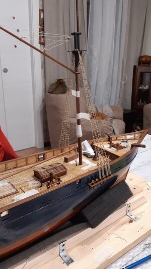
Mi riferisco alle sartie principali che (nelle navi vere) sostengono gli alberi.
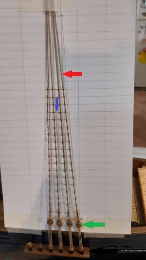
Prima di iniziare l'esposizione indico alcuni elementi che ho provato a tradurre con un glossario marittimo italiano-inglese ma che, per una migliore comprensione, evidenzio con frecce di diverso colore nelle foto allegate.
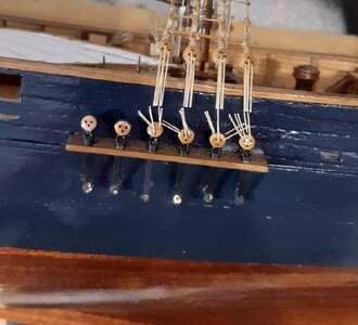
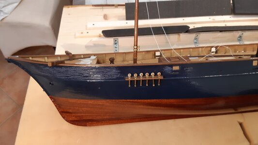
La freccia rossa indica le "sartie"
La freccia blu indica la "griselle" (rat line?)
La freccia gialla indica la "landre" (chain plate?)
La freccia nera indica il parasartie". (channel?)
La freccia verde indicale bigotte che letteralmente si traducono bigots. (deadeyes)

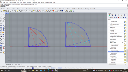
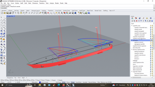
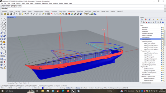
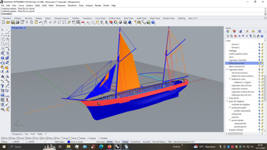
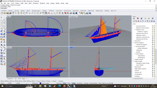
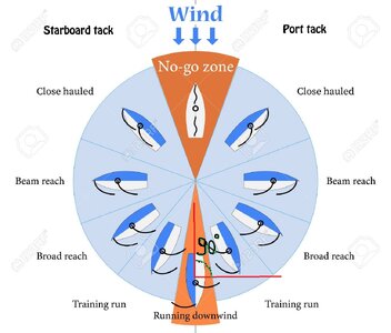
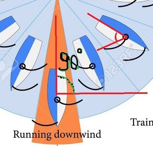
Come potete vedere nelle prime immagini delle schermate del software, avevo previsto un'apertura del boma fino a 90 gradi o quasi, rispetto alla linea longitudinale della nave (vista dall'alto).
Volevo una corsa del boma così ampia per l'andatura di poppa (vedi diagramma di corsa nell'immagine allegata).
Di conseguenza, per portare il boma in quella posizione di massima apertura, avrei dovuto posizionare le sartie maggiori (sei per lato) necessariamente nella posizione che vedete nelle schermate allegate (disegnate con Rhinoceros).

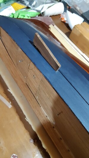
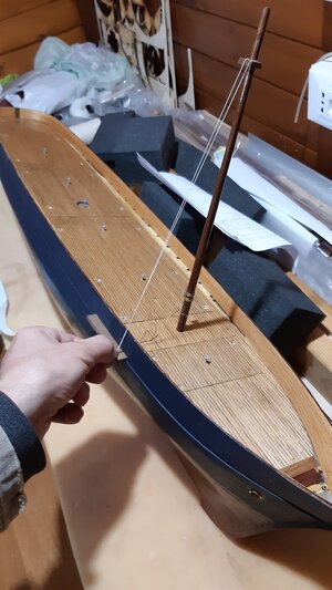
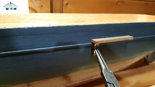
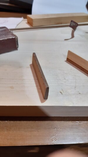
Le immagini che seguono mostrano le fasi costruttive dalle lande, dai parasartie alle sartie e alle griselle.
I parasartie non sono stati semplicemente incollati alla “murata”, ma direttamente alla foglio di compensato che costituisce il ponte superiore.
Per fare ciò è stato necessario effettuare un taglio “chirurgico” sullo scafo in corrispondenza degli spazi interni già predisposti.
In questo modo i parasartie potevano combaciare e incollarsi su una superficie diritta.
Il risultato è stato un'eccezionale robustezza dei parasartie.
L'intera nave a pieno carico potrebbe essere presa dai parasartie senza che questi possano staccarsi.
Sottolineo la fatica e il tempo spesi in questo lavoro perché tutto questo è stato inutile, ho dovuto togliere tutte le sartie, le cime, le lande e tagliare i parasartie, dovendo rifare tutto da capo.
Nelle ultime foto è presente uno studio delle vele effettuato con cartoncino bianco.
Ringrazio ancora tutti quelli che si sono interessati al mio lavoro. Ogni parere è sempre molto gradito e mi può far ragionare su qualcosa a cui non avevo pensato.
Le foto dopo la nr. 25 continuano nel seguente post dalla 26 in poi.

Hello to all members of this forum.

I'm almost at the current work in progress.

This phase that I am about to show you is a phase that I could have skipped, but I don't skip it because some very attentive forum users (keen observers) could notice a notable difference between the project and the final realization.
I am referring to the major shrouds that (in real ships) support the masts.

Before starting the exposition, I indicate some elements that I tried to translate with an Italian-English maritime glossary but which, for better understanding, I highlight with differently colored arrows in the attached photos.

The red arrow indicates the "shrouds"
The blue arrow indicates the "griselle" (rat line?)
The yellow arrow indicates the "landre" (chain plate?)
The black arrow points to the "shroud". (channel ?)
The green arrow points to the "bigoted". (deadeyes)

As you can see in the first images of the software screens, I had foreseen an opening of the boom up to 90 degrees or almost, compared to the longitudinal line of the ship (viewed from above).
I wanted such a wide boom travel for downwind running (see running diagram in the attached image).

Consequently, to get the boom to that maximum opening position, I would have had to position the major shrouds (six on each side) necessarily in the position you see in the attached screens (drawn with Rhinoceros).


The images following the screens show the construction phases from chain plates, channels to shrouds and rat lines.

The channels were not simply glued to the "bulwark", but directly to the plywood sheet that constitutes the upper deck.
To do this it was necessary to make a "surgical" cut on the hull in correspondence with the internal spaces already prepared.
In this way the channels could fit together and glue onto a straight surface.
The result was an exceptional robustness of the channels. The entire fully loaded ship could be taken by the channels without them being able to detach.

I'm emphasizing the effort and time spent on this job because all of this was useless, I had to remove all the shrouds, rat lines, chain plates, and cut the channels, having to do it all over again.

In the last photos there is a study of the sails carried out with white cardboard.
Thanks again to everyone who took an interest in my work. Any opinion is always very welcome and can make me think about something I hadn't thought of.
The photos after nr. 25 continue in the following post from 26 onwards.


top solo rinvvi.png

2 rinvii.png

3 rinvio.png

4 rinvio.png

5 rinvio.png

6 rinvio.png

20201120_165341.jpg

20201120_172238.jpg

20201111_201521.jpg

20201121_190247.jpg

20201121_193653.jpg

20201125_182249.jpg

20201128_195346.jpg

20201128_195351.jpg

20201128_200127.jpg

20201128_201635.jpg

20201128_203250.jpg

20201130_180151.jpg

20211003_175040.jpg

20211003_182947.jpg

20211017_002856.jpg

20211017_002902.jpg

20211017_012658.jpg

20211017_012700.jpg

20211017_020225.jpg
 
The red arrow indicates the "shrouds"
The blue arrow indicates the "griselle" (rat line?)
The yellow arrow indicates the "landre" (chain plate?)
The black arrow points to the "shroud". (channel ?)
The green arrow points to the "bigoted". (deadeyes)
I would say you nailed the translation of these parts.
 
Hello Alessandro,
With respect to your remarks on the boom angle of 90 degrees the following:
- My sailing instructor instructed me to not have the wind exactly coming from the six o'clock position on the downwind leg, due to the risk of jibbing; the wind is almost never from the exact same position, nor is the course your sailing an exact one. So he argued that, when sailing downwind, the wind always had to come from the upwind side of the boat.
- Shrouds typically run from almost in line to the mast to a certain distance aft of the mast, on square rigged ships this might be rather pronounced, due to the fact that their incapability to sail very close to the wind, so the forces on the sails and masts would originate more from between halfwind or downwind directions. On fore/aft rigged ships, although being able to sail close to the wind, still have their shrouds from parallel to the masts to aft of the masts, which is clearly visible on the Bluenose schooner. This prevents the boom to go to a full 90 degree deflection. The gaffs however are not so limited and may rotate to 90 degrees, or a bit more, depending on geometry. Not having available any data on your model, I haphazard a guess that the shrouds were oriented quite similar to the other schooner of the day.
Ciao Johan.

Quello che scrivi è, come al solito, molto interessante.

Peccato che io non sia riuscito ad capire bene tutto al cento per cento.
Quello che sono riuscito a comprendere mi trova d'accordo con te.

Non so come tradurre jibbing, ma dal discorso che hai fatto penso di aver capito il concetto.
Forse è questo: quando si naviga "running" cioò con il vento che viene esattamente da dietro (ad ore sei come dici tu) il boma è tutto lascato ed è pericoloso prechè può passare repentinamente dalla parte opposta ("to gybe" forse?).

Forse stai anticipando quello che stavo scrivendo per spiegare in che consiste il mio errore.

Come avevo già accennato nel post precedente, la posizione delle sartie era determinata dalla posizione del boma nella sua massima escursione, cioè a circa novanta gradi (o poco meno) tra il boma stesso e l'asse longitudinale della nave.
In altre parole nel progetto avevo posizionato le sartie nella posizione più arretrata possibile, ma tale da non impedire al boma di spostarsi e di formare quasi un angolo retto con la linea longitudinale dello scafo (visto dall'alto).

Come avete potuto vedere dalle foto dell'ultimo post descrittivo, in questo modo le sartie vengono poste un po' avanti e un po' dietro gli alberi, non tutte dietro.

Ebbene, col passare del tempo mi sono reso conto di aver commesso un errore anche se avevo seguito un ragionamento abbastanza logico.

Più osservavo navi di quell'epoca e di quel tipo, per carpire altri dettagli costruttivi da riprodurre in scala sul mio modello, più mi rendevo conto di aver sbagliato qualcosa.

Indubbiamente le sartie dovevano essere posizionate molto più indietro.
Ho subito notato che, spostando le sartie all'indietro, il boma non riusciva a formare un angolo retto.
L'angolo sarebbe stato molto più stretto, e non di poco.

Questo mi sembrava strano, quindi ho pensato che fosse solo una caratteristica del mio modello. Quindi ho verificato facendo alcune simulazioni su altre navi esistenti con almeno una vela aurica (una randa).
Dovevo tenere conto che le sartie erano tutte a poppavia dell'albero, anche se questo limitava la corsa del boma.
Non c'è nave di quell'epoca che ne abbia una a prua.
Non essendo un progettista navale di quell’epoca, non essendo un marinaio di quell’epoca o un marinaio che naviga su navi auriche ho fatto solo congetture.

Avrei dovuto avere la fortuna di incontrare e parlare con qualcuno della nave scuola italiana "Palinuro", meno conosciuta dell'"Amerigo Vespucci" ma bella e allestita come una goletta, che era ciò di cui avevo bisogno.

Le congetture consistevano nel chiedermi perché le sartie delle navi dell'epoca (in realtà anche sulle navi di epoche precedenti) si trovavano in quella posizione?
Perchè rinunciare ad aprire completamente la randa per andare sottovento?

Ecco la mia spiegazione:
Le sartie maggiori hanno due funzioni principali.
La prima funzione è quella di mantenere stabile l'albero trasversalmente. Per fare questo (è abbastanza intuitivo) lavorano in contrasto (lato destro contro lato sinistro) per mantenere l'albero in posizione ferma.
La seconda funzione è quella di garantire anche la stabilità longitudinale (attenzione, vi ricordo che stiamo parlando di golette, quindi di armo aurico). Per questo motivo tirano l'albero all'indietro, lavorando in contrasto con gli stralli che tirano in avanti.
Questa seconda funzione era probabilmente considerata più importante della necessità di aprire completamente il boma, raggiungendo i 90 gradi o quasi.
Inoltre, è probabile che l'andatura sottovento non fosse una priorità in quanto, come è noto, è la più scomoda e raramente utilizzata dalle navi a vela, nemmeno da quelle da diporto.
Sicuramente sai perché, quindi non mi dilungherò su questo.
Per le andature portanti è sicuramente più comodo raggiungere l'andatura, per cui è sufficiente l'apertura del boma consentita dalle sartie posteriori.

Alla luce di queste scoperte ho dovuto prendere la decisione più difficile da quando ho iniziato il progetto.

Alla fine mi sono fatto coraggio, perché non riuscivo a vedere un errore così evidente e ho distrutto tutto.

Nel prossimo post illustrerò le fasi di rottura, recupero dei pezzi e ricostruzione totale delle sartie.


Hi Johan.

What you write is, as usual, very interesting.
Too bad I wasn't able to understand everything one hundred percent.
What I managed to understand I agree with you.
I don't know how to translate jibbing, but from what you said I think I understand the concept.
Maybe it's this: when sailing "running" that is, with the wind coming exactly from behind (at six o'clock as you say) the boom is completely loose and is dangerous because it can suddenly pass to the opposite side ("to gybe" perhaps?) .

Maybe you're anticipating what I was writing to explain what my mistake consists of.


As I had already stated in the previous post, the position of the shrouds was determined by the position of the boom at its maximum excursion, i.e. around ninety degrees (or a little less) between the boom itself and the longitudinal axis of the ship.
In other words, in the project I had placed the shrouds in the most rearward position possible, but such as not to prevent the boom from moving and forming almost a right angle with the longitudinal line of the hull (seen from above).

As you could see from the photos in the last descriptive post, in this way the shrouds are placed a little forward and a little behind the masts, not all behind.

Well, as time went by I realized that I had made a mistake even though I had followed a fairly logical argument.

The more I observed ships of that era and of that type, to glean other construction details to reproduce in scale on my model, the more I realized that I had done something wrong.

Unmistakably the shrouds had to be placed much further back.
I immediately noticed that, by moving the shrouds backwards, the boom would not be able to form a right angle.
The angle would have been much narrower, and not by a little.

This seemed strange to me, so I thought it was just a feature of my model. So I checked by doing some simulations on other existing ships with at least one gaff sail (a mainsail).
I had to take note that the shrouds were all aft of the mast, even though this limited the boom's travel.
There isn't a ship from that era that even has some in the bow.
Not being a naval designer of that era, not being a sailor of that era or a sailor who sails on gaff rigged ships I only made conjectures.

I should have been lucky enough to meet and talk to someone from the Italian training ship "Palinuro", less well known than the "Amerigo Vespucci" but beautiful and rigged as a schooner, which is what I needed.

The conjectures consisted in asking me why the shrouds of the ships of the time (in reality also on the vessels of previous times) were in that position?
Why give up opening the mainsail completely for downwind running?

Here is my explanation:
The main shrouds have two main functions.
The first function is to keep the mast stable transversely. To do this (it's quite intuitive) they work in contrast (the right side against the left side) to keep the tree in a firm position.
The second function is to also guarantee longitudinal stability (be careful, I remind you that we are talking about schooners, therefore gaff rigs). For this reason they are pulled back and pull the mast backwards, working in contrast to the stays which pull forward.
This second function was probably considered more important than the need to open the boom completely, reaching 90 degrees or almost.
Furthermore, it is probable that the running downwind pace was not a priority as it is well known that it is the most inconvenient and rarely used by sailing ships, not even by pleasure boats.
Surely you know why, so I won't dwell on it.
For downwind sailing, reaching sailing is certainly more convenient, so the opening of the boom allowed by the rear shrouds is sufficient.


In light of these discoveries I had to make the most difficult decision since I started the project.

In the end I got courageous, because I couldn't see such a clear mistake and I destroyed everything.

In the next post I will illustrate the phases of breakage, recovery of the pieces and total reconstruction of the shrouds.


andature inglesi.jpg

andature inglesi - Copia.jpg
 
Last edited:
To jibb, to gybe, I think they're synonyms.

Again a big thank you for your very extensive answer to my remarks.
Until now it was my understanding that shrouds are primarily meant for sideways support and that (back) stays are used to trim sails and to apply tension on the other stays.
The Bluenose schooner carried two (LH &RH) topmast flying backstays, although there is also some evidence showing lower mast backstays.
I do understand you decided to redo the shrouds; once you realize they are not correct, your eyes will always be drawn to the sore spot. So a redo is in order...
I think the diagrams you added are self explanatory; sailing a course with the wind coming exactly from your six o'clock is not advisable. This also eliminates the need for a 90 degree rotation angle on your boom.
I wish you good luck with your redo.
Ciao Johan.


"Again a big thank you for your very extensive answer to my remarks." Per me è un piacere dialogare con te e con gli altri ragazzi di questo forum.


"I do understand you decided to redo the shrouds; once you realize they are not correct, your eyes will always be drawn to the sore spot. So a redo is in order..."
Verissimo. E' proprio così.


"I think the diagrams you added are self explanatory; sailing a course with the wind coming exactly from your six o'clock is not advisable. This also eliminates the need for a 90 degree rotation angle on your boom."
Posso aggiungere che lo svantaggio è ancora maggiore per i velieri con vele quadre. Infatti in questo caso le vele del mizenmast o comunque del mast più arretrato toglieranno completamente il vento a tutte le vele davanti a loro.
Nelle golette questo può essere ovviato con la disposizione "a farfalla".

Grazie Johan.


Hi Johan.

"Again a big thank you for your very extensive answer to my remarks."
It's a pleasure for me to talk with you and the other guys on this forum.

"I do understand you decided to redo the shrouds; once you realize they are not correct, your eyes will always be drawn to the sore spot. So a redo is in order..."
Very true. That's it.

"I think the diagrams you added are self explanatory; sailing a course with the wind coming exactly from your six o'clock is not advisable. This also eliminates the need for a 90 degree rotation angle on your boom."
I can add that the disadvantage is even greater for square-rigged sailing ships. In fact in this case the sails of the mizenmast or in any case of the rearmost mast will completely remove the wind from all the sails in front of them.
In schooners this can be overcome with the "butterfly" arrangement.

Thanks Johan.
 
Un saluto a tutti voi modellisti.

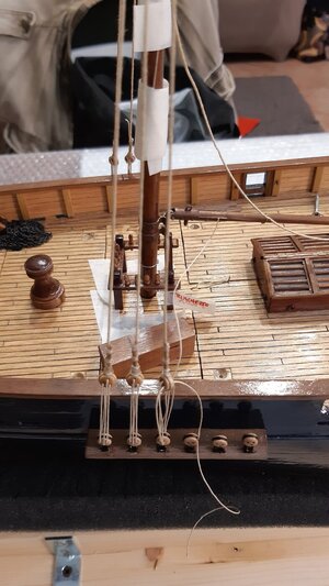
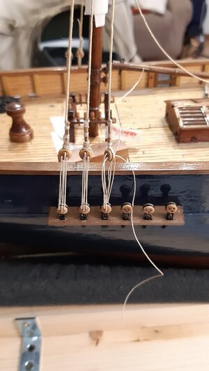
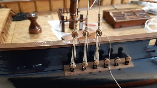
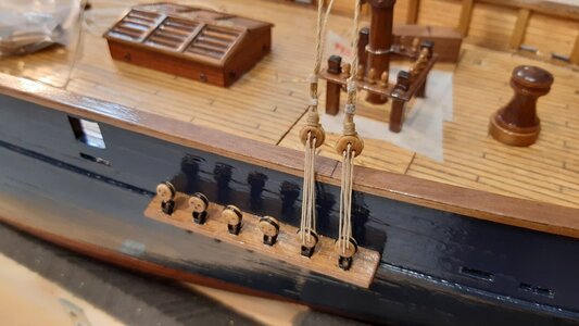
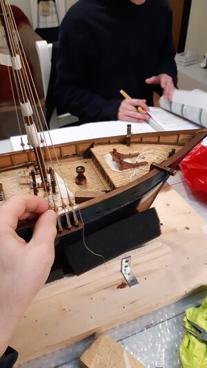
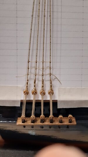
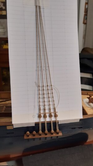
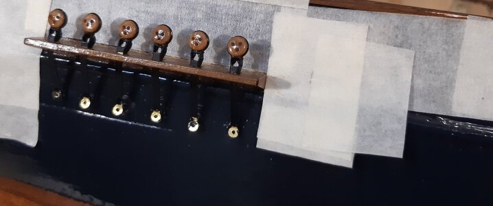
Ecco la prima foto del taglio traumatico: il filo utilizzato per stringere (tendere) le "bigotte" (deadeyes).
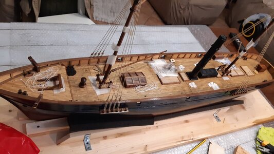
Per fortuna (e sinceramente non me lo aspettavo) sono riuscito a riutilizzare quasi tutte le parti tagliate, tutte tranne le sartie e le griselle.
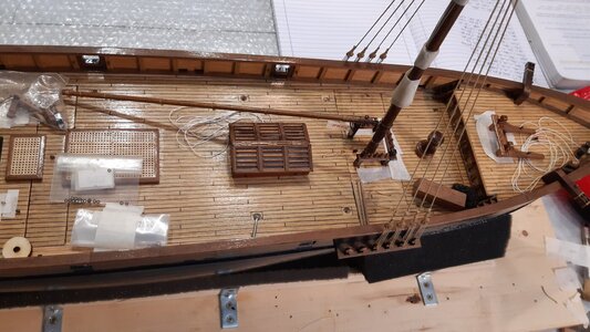
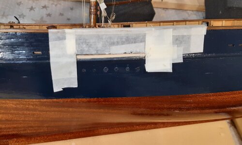
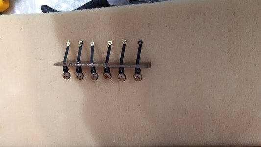
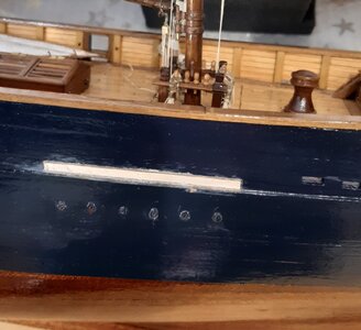
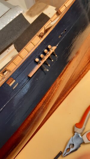
È stato molto difficile tagliare i parasartie a filo dello scafo. Sono riuscito ad essere preciso con il taglierino e quindi ho recuperato i parasartie, che ho incollato più indietro.
Ho tolto tutte le "landre", che ho ridipinto e riutilizzato.
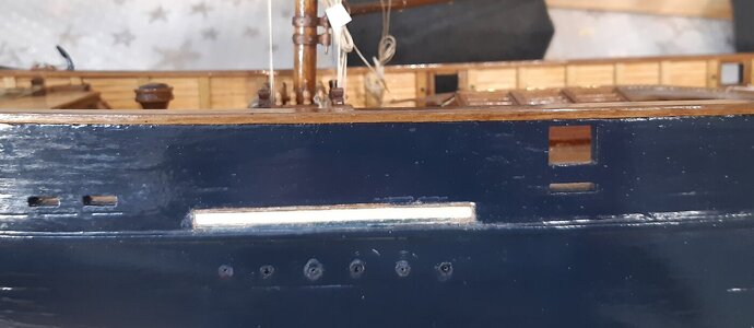
Ho dovuto tappare i buchi rimasti sulla landra e farne altri più dietro, riverniciando anche lo scafo.
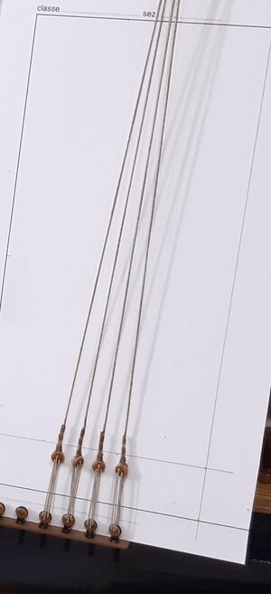
Tutti i deadeye (che erano stati verniciati per l'impermeabilizzazione) sono stati recuperati.
È stato difficile staccare le sartie in testa d'albero senza causare danni.
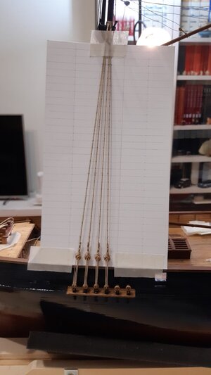
Le sartie sono legate a coppie sull'albero e non è facile dare la giusta tensione sia alla coppia sinistra che a quella destra e allo stesso tempo far allineare tutti i deadeyes.
Logicamente tutte le sartie vecchie sono state gettate via perché non riutilizzabili.
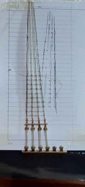
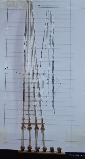
Le ho rifatte daccapo e ho legato la griselle usando un disegno guida sulla carta.

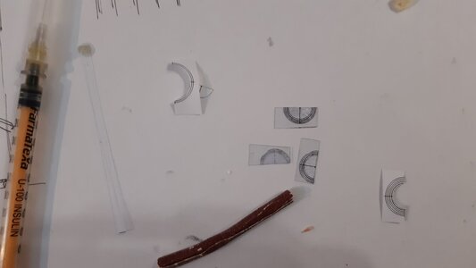
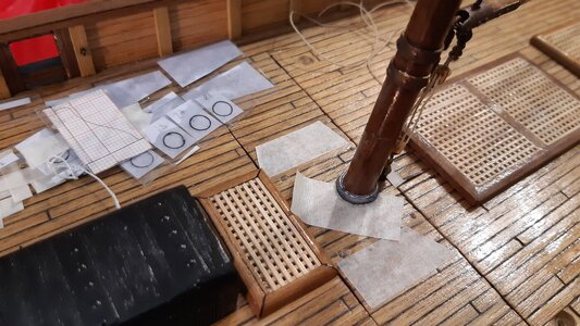
In questo stesso post vi mostro il piede d'albero.
Amati, Corel, Mantua Model e Mamoli li vendono già pronti, ma non ce n'erano che facessero al caso mio ed erano tutti metallici.
Le ultime foto mostrano come appariva prima di dipingerlo in modo che sembrasse reale. Ho usato il solito modo di sovrapporre la plastica.
Il piede dell'albero è molto importante non solo per coerenza storica ed estetica ma anche per evitare che l'acqua entri in quel punto.

Greetings to all you modelers.

Here is the first photo of the traumatic cut: the thread used to tighten (tension) the "bigotte" (deadeyes).
Luckily (and I honestly didn't expect it) I managed to reuse almost all the cut parts, all except the shrouds and rat lines.
It was very difficult to cut the channels flush with the hull. I managed to be precise with the cutter and therefore I recovered the channels, which I glued further aft.
I removed all the "chains plates", which I repainted and reused.
I had to plug the holes left in the chain plate and make others further behind, also repainting the hull.
All the deadeyes (which had been painted for waterproofing) were recovered.
It was difficult to detach the shrouds at the masthead without causing damage.
The shrouds are tied in pairs on the tree and it is not easy to give the right tension to both the left and right pairs and at the same time get all the deadeyes to align.
Logically all the shrouds were thrown away as they were not repairable.
I made them again and tied the griselle (rat line) using a guide design on the card.

In this same post I show you the mast foot.
Amati, Corel, Mantua Model and Mamoli sell them ready-made, but there were none that were right for me and they were all metallic.
The last photos show how it looked before painting it so that it looked real. I used the usual way of overlapping plastic.
The foot of the tree is very important not only for historical and aesthetic coherence but also to prevent water from entering that point.


20221223_125653.jpg

20221223_162046.jpg

20221223_180136.jpg

20221223_180155.jpg

20221223_181058.jpg

20221223_201635.jpg

20230416_185900.jpg

20230424_203309.jpg

20230424_203313.jpg

20230424_203319.jpg

20220508_181416.jpg

20220508_181407.jpg
 
Back
Top