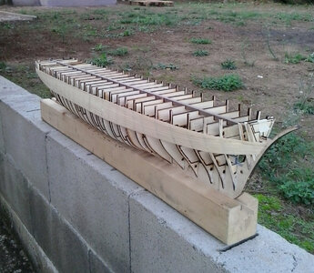
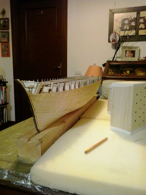
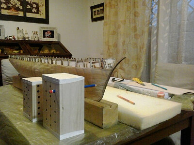
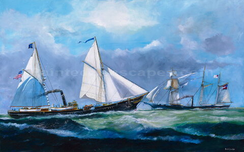
1/60 scale RC model of a schooner, loosely based on a gunboat steamship from the second half of the 19th century.

Joined
Sep 22, 2023
Messages
173
Points
143

Modello RC in scala 1/60 di goletta, liberamente ispirato ad un piroscafo cannoniera della seconda metà del 1800.

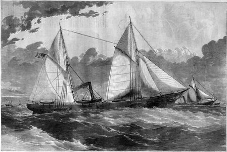
Per "liberamente ispirato" intendo che non avevo nè immagini dettagliate nè piani ma solo queste litografie che allego.

Ho scelto questo tipo di nave perchè in quel periodo la vela e la propulsione ad elica hanno convissuto.
In questo modo ho potuto costruire un modello RC navigante a vela e a motore, storicamente coerente.

Si tratta di cannoniere della classe USS Unadilla che hanno combattuto nella guerra civile americana.

Era importante che il modello potesse entrare nel bagagliaio di un'autovettura e questo tipo di nave, se fatto in scala 1/60, andava bene.

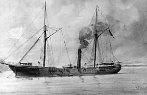
By "freely inspired" I mean that I had neither detailed images nor plans but only these lithographs that I attach.
I chose this type of ship because in that period sailing and propeller propulsion coexisted.
In this way I was able to build a historically coherent sailing and motor RC model.
These are USS Unadilla class gunboats that fought in the American Civil War.
It was important that the model could fit in the trunk of a car and this type of ship, if made in 1/60 scale, was fine.
300px-USS_Cayuga_(1861).jpg

1864-USS-Winona-against-the-Roanoke.jpg

098604304.jpg
 
Quando ho intrapreso il progetto avevo pochissime conoscenze nautiche.
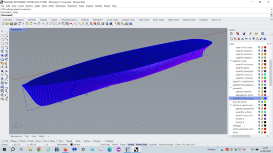
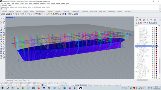
Per il progetto ho usato il programma 3d Rhinoceros, che ho imparato (solo parzialmente) per questa esigenza.

Inizialmente, la classe USS Unadilla mi è servita solo come punto di partenza;
Man mano che la costruzione procedeva, pur seguendo il mio progetto per lo scafo e la parte dinamica, cercavo sempre più particolari e dettagli per una ricostruzione coerente.

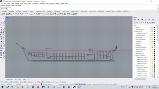
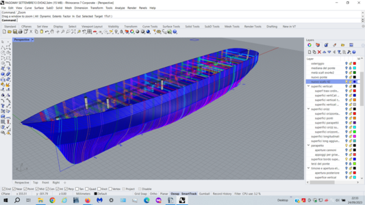
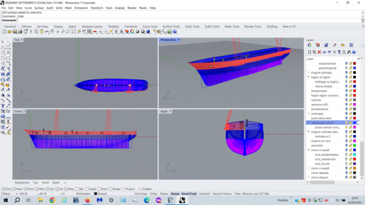
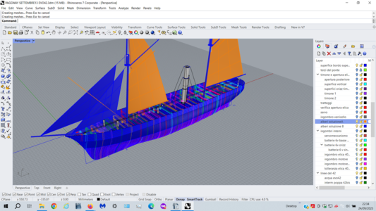
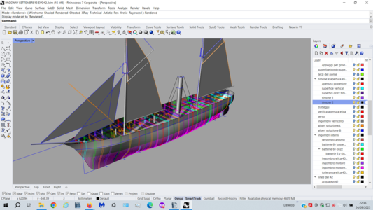
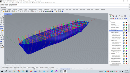
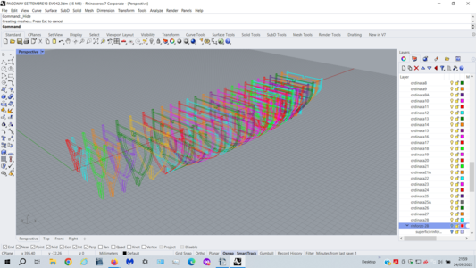
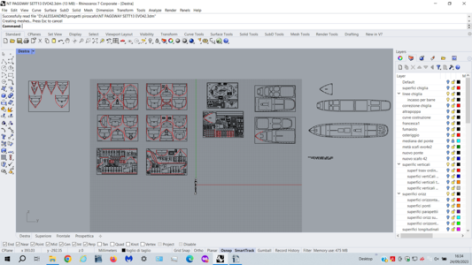
Nel link video e nelle immagini potete vedere alcuni degli aspetti salienti del progetto.
In estrema sintesi dal disegno della ciglia e delle linee principali ho creato (con moltissime difficoltà) la superficie dello scafo. dalla suferice dello scafo, ho creato le varie ordinate che ho posizionato su vari fogli per il successivo taglio.

When I undertook the project I had very little nautical knowledge.
For the project I used the 3D program Rhinoceros which I learned (only partially) for this need.

Initially, the USS Unadilla class only served as a starting point for me;
As the construction progressed, while following my project for the hull and the dynamic part, I was looking for more and more details for a coherent reconstruction.

In the video link and in the images you can see some of the salient aspects of the project.

In a nutshell, from the design of the eyelash and the main lines I created (with great difficulty) the surface of the hull. from the surface of the hull, I created the various frames which I positioned on various sheets for subsequent cutting.


solo chiglia.png

scafo e ordinate.png

con sartie.png

con fumaiolo e alberi.png

con timone.png

ordinate e scafo.png

solo ordimate.png

tavole per il taglio.png

volume immerso.png

volume immerso con ordinate.png
 
To be honest, I am quite interested in your design- and build process. Currently I am close to complete another Bluenose build and I started thinking about the next project. One of the options being considered is a typical Dutch, steam driven tug from the early twentieth century. It's rather likely that drawings are available, but those are more of than not very unreliable.
 
To be honest, I am quite interested in your design- and build process. Currently I am close to complete another Bluenose build and I started thinking about the next project. One of the options being considered is a typical Dutch, steam driven tug from the early twentieth century. It's rather likely that drawings are available, but those are more of than not very unreliable.
Grazie molto RDN1954.

Ho imparato solo una minima parte dei comandi di Rhinoceros, molto tempo fa. Però mi sono bastati per il mio scopo, cioè ottenere: chiglia, frames, e deck da ritagliare su legno.
E' vero quello che scrivi, disegnare la superfice dello scafo è stato difficilissimo. Infatti, ci sono piccole imperfezioni a prua, che ho eliminato in fase costruttiva (carta vetrata).
Inoltre non sono riuscito a chidere i volumi dello scafo. Quest'ultimo non è un problema per la costruzione, perchè sono errori invisibili, ma ciò mi ha impedito di ottenere informazioni automaticamente dal software stesso.
Ad esempio avrei potuto sapere, automaticamente, con un solo comando, il volume immerso in mm3 e la posizione esatta del centro di carena 8ferse si dice "centre of buoyancy"). Questi problemi non sono riusciti a risolverli nemmeno degli Youtuber che pubblicavano tutorial su Rhinoceros. Perciò sono andato avanti perchè mi ero scocciato di disegnare e volevo costruire (segare, scartavetrare, bucare, incollare ecc. ecc.)

Thanks very much RDN1954.

I only learned a fraction of the Rhinoceros commands, a long time ago. But they were enough for my purpose, that is to obtain: keel, frames, and deck to be cut out of wood.

What you write is true, drawing the surface of the hull was very difficult. In fact, there are small imperfections on the bow, which I eliminated during the construction phase (sandpaper).
Furthermore, I was unable to close the hull volumes. The latter is not a problem for the construction, because they are invisible errors, but this prevented me from obtaining information automatically from the software itself.
For example, I could have known, automatically, with a single command, the volume immersed in mm3 and the exact position of the center of the hull (8ferse it is called "center of buoyancy"). Even Youtubers who posted tutorials on Rhinoceros couldn't solve these problems.
So I went ahead because I was bored with drawing and wanted to build (sawing, sanding, drilling, gluing etc. etc.)
 
A highly interesting project - I am looking forward to see much more of your work
Grazie mille Uwek.

Continuerò ad illustrare le fasi di montaggio.
Ho proceduto da autodidatta ma ho seguito molti consigli utili.
In alcuni casi, la soluzione che ho adotatto, per uno specifico problema, non era forse la migliore.
Non abbiate timore di commentare negativamente alcune scelte.
Se, però, qualche scelta tecnica, un pò fuori standard, potrà essere utile agli altri sarò veramente contento.

Thank you very much Uwek.

I will continue to illustrate the assembly phases.
I proceeded as a self-taught but I followed many useful tips. In some cases, the solution I adopted for a specific problem was perhaps not the best.
Don't be afraid to comment negatively on some choices.
If, however, some technical choices, a little out of standard, can be useful to others I will be really happy.
 
Buona sera (o buon giorno) a tutti.

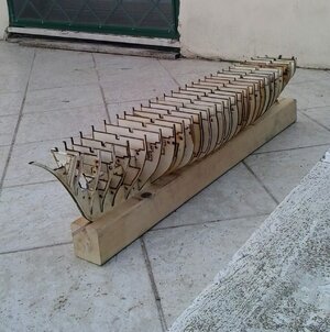
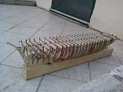
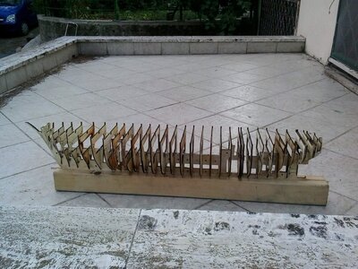
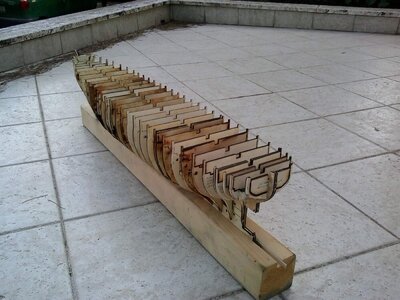
Una volta ottenute le frames, la chiglia e i ponti per il taglio, ho inziato a lavorare manualmente.
Per essere più veloce, decisi di provare per la prima volta il taglio laser, invece del classico seghetto a traforo (seghetto ad arco).
Sono andato da un amico che lo usava per la prima volta sul legno compensato da 4 mm di spessore.
Il risultato è stato disastroso, invece di un taglio perfetto ha bruciato tutti i bordi.
Volevo buttare tutto e ricominciare, invece ho deciso di proseguire. Sarebbe stato meglio rifare il taglio ma il legno da buttare era molto.
Vi sto spiegando questo perchè vedrete le ordinate con i segni di bruciato.

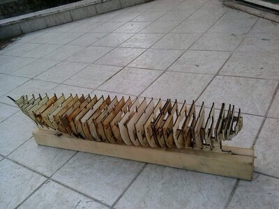
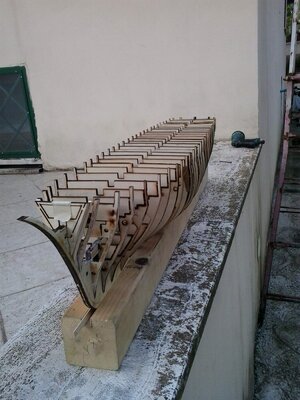
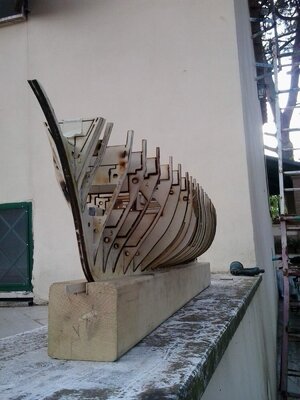
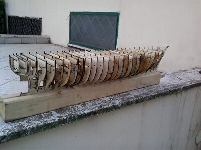
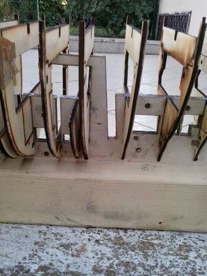
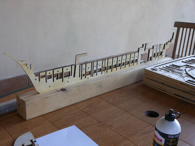
Il risultato è stato che le frames "ballavano" sulla chiglia, invece di incastrarsi perfettamente, come avrebbero dovuto.
Nelle immagini potete vedere anche la predisposizione per un regolo per allineare ulteriormente tutte le ordinate.
Insomma, ho dovuto faticare tantissimo e spendere molto più tempo per curare la giusta posizione di ogni frame.
Iniziavamo proprio male.

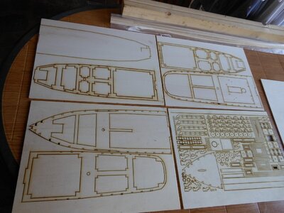
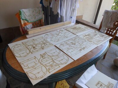
I cerchi e i quadrati che vedete sulle singole ordinate, sono i pretagli per far passare cavi o elementi di rinforzo come quadrelli di legno.
Le forme strane sono gli alloggiamenti per il motore, gli alberi., ecc. ecc. In seguito sarà tutto più chiaro.
Una volta finito il fasciame dello scafo, la parte interna delle frames andra tolto e rimarranno solo delle sottili costole.

Good evening (or good morning) everyone.

Once I had the frames, the keel and the decks for cutting I started working manually.
To be faster, I decided to try laser cutting for the first time, instead of the classic fret saw (bow saw).
I went to a friend who was using it for the first time on 4mm thick plywood.
The result was disastrous, instead of a perfect cut it burned all the edges.
I wanted to throw everything away and start again, but instead I decided to continue.
It would have been better to redo the cut but there was a lot of wood to throw away.
I'm explaining this to you because you will see the frames with burn marks.

The result was that the frames "danced" on the keel, instead of fitting together perfectly, as they should have.
In the images you can also see the provision for a ruler to further align all the ordinates.
In short, I had to work a lot and spend a lot more time getting the right position for each frame.
We started off really badly.

The circles and squares that you see on the individual frames are the pre-cuts for passing cables or reinforcing elements such as wooden squares.
The strange shapes are the engine housings, the shafts, etc. etc.
Everything will be clearer later.
Once the hull plating is finished, the internal part of the frames will be removed and only thin ribs will remain.

I hope I was understandable.


si possono evitare - Copia.jpg

tav1 - Copia.jpg

20140820_162627.jpg

20140820_162635.jpg

20140820_162640.jpg

20140820_162651.jpg

20140820_162656.jpg

20140820_162718.jpg

20140820_162725.jpg

20140820_162811.jpg

20140820_162821.jpg
 
Grazie molto RDN1954.

Ho imparato solo una minima parte dei comandi di Rhinoceros, molto tempo fa. Però mi sono bastati per il mio scopo, cioè ottenere: chiglia, frames, e deck da ritagliare su legno.
E' vero quello che scrivi, disegnare la superfice dello scafo è stato difficilissimo. Infatti, ci sono piccole imperfezioni a prua, che ho eliminato in fase costruttiva (carta vetrata).
Inoltre non sono riuscito a chidere i volumi dello scafo. Quest'ultimo non è un problema per la costruzione, perchè sono errori invisibili, ma ciò mi ha impedito di ottenere informazioni automaticamente dal software stesso.
Ad esempio avrei potuto sapere, automaticamente, con un solo comando, il volume immerso in mm3 e la posizione esatta del centro di carena 8ferse si dice "centre of buoyancy"). Questi problemi non sono riusciti a risolverli nemmeno degli Youtuber che pubblicavano tutorial su Rhinoceros. Perciò sono andato avanti perchè mi ero scocciato di disegnare e volevo costruire (segare, scartavetrare, bucare, incollare ecc. ecc.)

Thanks very much RDN1954.

I only learned a fraction of the Rhinoceros commands, a long time ago. But they were enough for my purpose, that is to obtain: keel, frames, and deck to be cut out of wood.

What you write is true, drawing the surface of the hull was very difficult. In fact, there are small imperfections on the bow, which I eliminated during the construction phase (sandpaper).
Furthermore, I was unable to close the hull volumes. The latter is not a problem for the construction, because they are invisible errors, but this prevented me from obtaining information automatically from the software itself.
For example, I could have known, automatically, with a single command, the volume immersed in mm3 and the exact position of the center of the hull (8ferse it is called "center of buoyancy"). Even Youtubers who posted tutorials on Rhinoceros couldn't solve these problems.
So I went ahead because I was bored with drawing and wanted to build (sawing, sanding, drilling, gluing etc. etc.)
It would have helped tremendously if you would have been able to generate proper surface- and volume defintions. I am not familiar with Rhinoceros, but the earlier versions of CATIA, a Dassault Systêmes product, had similar issues, even to the extend it was not really useful.
 
Buona sera (o buon giorno) a tutti.

Una volta ottenute le frames, la chiglia e i ponti per il taglio, ho inziato a lavorare manualmente.
Per essere più veloce, decisi di provare per la prima volta il taglio laser, invece del classico seghetto a traforo (seghetto ad arco).
Sono andato da un amico che lo usava per la prima volta sul legno compensato da 4 mm di spessore.
Il risultato è stato disastroso, invece di un taglio perfetto ha bruciato tutti i bordi.
Volevo buttare tutto e ricominciare, invece ho deciso di proseguire. Sarebbe stato meglio rifare il taglio ma il legno da buttare era molto.
Vi sto spiegando questo perchè vedrete le ordinate con i segni di bruciato.

Il risultato è stato che le frames "ballavano" sulla chiglia, invece di incastrarsi perfettamente, come avrebbero dovuto.
Nelle immagini potete vedere anche la predisposizione per un regolo per allineare ulteriormente tutte le ordinate.
Insomma, ho dovuto faticare tantissimo e spendere molto più tempo per curare la giusta posizione di ogni frame.
Iniziavamo proprio male.

I cerchi e i quadrati che vedete sulle singole ordinate, sono i pretagli per far passare cavi o elementi di rinforzo come quadrelli di legno.
Le forme strane sono gli alloggiamenti per il motore, gli alberi., ecc. ecc. In seguito sarà tutto più chiaro.
Una volta finito il fasciame dello scafo, la parte interna delle frames andra tolto e rimarranno solo delle sottili costole.

Good evening (or good morning) everyone.

Once I had the frames, the keel and the decks for cutting I started working manually.
To be faster, I decided to try laser cutting for the first time, instead of the classic fret saw (bow saw).
I went to a friend who was using it for the first time on 4mm thick plywood.
The result was disastrous, instead of a perfect cut it burned all the edges.
I wanted to throw everything away and start again, but instead I decided to continue.
It would have been better to redo the cut but there was a lot of wood to throw away.
I'm explaining this to you because you will see the frames with burn marks.

The result was that the frames "danced" on the keel, instead of fitting together perfectly, as they should have.
In the images you can also see the provision for a ruler to further align all the ordinates.
In short, I had to work a lot and spend a lot more time getting the right position for each frame.
We started off really badly.

The circles and squares that you see on the individual frames are the pre-cuts for passing cables or reinforcing elements such as wooden squares.
The strange shapes are the engine housings, the shafts, etc. etc.
Everything will be clearer later.
Once the hull plating is finished, the internal part of the frames will be removed and only thin ribs will remain.

I hope I was understandable.


View attachment 396595

View attachment 396596

View attachment 396597

View attachment 396598

View attachment 396599

View attachment 396600

View attachment 396601

View attachment 396602

View attachment 396603

View attachment 396604

View attachment 396605
How was the accuracy of the laser-cut parts? Apparently you experienced quite some variation in the energy output, which may lead to inconsistent dimensional variations.
Another noteworthy phenomenon is the large number of frames. Did you copy the exact same number of frames in your build?
 
Buongiorno RDN1954 e salute a tutti i modellisti.

Si, credo che tu abbia ragione.
Normalmente il taglio laser è molto preciso e veloce.
A differenza del seghetto che "mangia" almeno un millimetro di legno, la perdita con il taglio laser è esigua, è trascurabile.
Questo normalmente però. Nel mio caso il laser del mio amico non ha funzionato bene, ha bruciato troppo e mi ha fatto perdere molto più legno del dovuto; ecco perchè le frames "ballavano" sulla chiglia invece di incastrarsi alla perfezione.

E' vero le frames sono molte. E' stata una scelta iniziale voluta.
Sono consapevole che i piani e i kit non prevedono molte frames per la costruzione.
In fase di progetto ho immaginato quali potessero essere i vantaggi di questa scelta.
In primis: Mettere molte frames mi avrebbe aiutato a posizionate il primo fasciame, per il metodo che uso io. Infatti non uso chiudini o altri oggetti per fermare i listelli di legno ma solo la colla, tipo mastice.
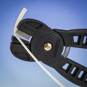
Considera che in quel tempo non conoscevo la "pinza piegalistelli". Un oggetto semplice, economico, ma efficientissimo. L'ho scoperta mentre lavoravo al secondo fasciame.
In questo caso avere più frames vuol dire avere maggiore superfice di incollaggio. Estremizzando il metodo si avrebbe già uno scafo con le sole frames.
In secundis: Molte frames sono utili per predisporre già gli alloggiamenti (e le basi ortogonali) per le batterie, per il motore, per l'asse portaelica, per i servomeccanismi, ecc. ecc.
Tertium non datur, ahahahahah.

Essendo un modello navigante RC, dovevo stare molto attento al peso, e non superare i 5 kg di dislocamento, che mi sono imposto per rispettare la linea di galleggiamento disegnata. Dovevo risparmiare su tutto perciò, per compensare il peso di tante frames, ho tolto quasi tutto il legno interno di ogni frame che, alla fine si sono ridotte a delle costole.
Nel mio caso costolette alla brace.

Yes, I think you're right.

Normally laser cutting is very precise and fast.
Unlike the hacksaw which "eats" at least a millimeter of wood, the loss with laser cutting is small, it is negligible.
This is normal though. In my case my friend's laser didn't work well, it burned too much and made me lose much more wood than it should; this is why the frames "danced" on the keel instead of fitting perfectly.

It's true there are many frames. It was a deliberate initial choice.
I am aware that the plans and kits do not include many frames for construction.
During the design phase I imagined what the advantages of this choice could be.
First of all: Putting many frames would have helped me position the first planking, for the method I use. In fact, I don't use closures or other objects to secure the wooden strips but only glue, like putty.
Consider that at that time I didn't know the "bending pliers". A simple, economical, but very efficient object. I discovered it while I was working on the second planking.In this case, having more frames means having a greater bonding surface.
Taking the method to the extreme you would already have a hull with only frames.
Secondly: Many frames are useful for already preparing the housings (and orthogonal bases) for the batteries, for the motor, for the propeller shaft, for the servomechanisms, etc. etc.
Tertium non datur, ahahahahah.

Being an RC sailing model, I had to be very careful about the weight, and not exceed the 5 kg of displacement, which I imposed on myself to respect the designed waterline.
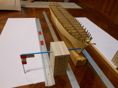
I had to save on everything so, to compensate for the weight of so many frames, I removed almost all the internal wood from each frame which in the end was reduced to ribs.
In my case grilled ribs.
Very impressive; a lot of design effort went into your model.
I can't oppose to the number of frames you used, other than that there seems to be some redundancy, especially in the more or less constant cross section area of the hull. Having additional frames in stem and stern are very helpful in planking the hull.
Laser-cut parts are in general very accurate, the main drawback being the char removal; I spend countless hours sanding.
I'm surprised you had to use bending pliers; the curvatures seem to be rather benign. But a useful tool it is.
Le tue osservazioni sono corrette.
Considera, però, che molte scelte sono state fatte quando le mie conoscenze erano molto limitate. In fase di realizzazione ho acquisito man mano molte informazioni da libri e su internet (testi, immagini e video).
Oggi sono soddisfatto solo di alcune scelte tecniche che ho adottato, anche se inconsuete, ma molte scelte sono invece da evitare, oggi non le rifarei.
Per quanto riguarda le "bending pliers" , non ne ho avuto bisogno finchè gli scafi dei modelli avevano un " transom" piatto. In questo caso, come dici tu giustamente: "le curvature sembrano essere piuttosto benigne".
In questo modello la poop, invece, è tonda e le curvature sono molto accentuate, bisogna fare addirittura un cerchio sui listelli più vicini al ponte.
Per non spezzarli si possono usare molti metodi: la candela, il vapore, l'acqua bollente ecc. ecc. Tutti medoti molto laboriosi e lunghi secondo me.
La pinza piegalistelli è geniale per quanto semplice, piega il listello grazie a delle tacche che fa sul legno, senza spezzarlo.
Più sono fitte le tacche che si fanno tanto più la curvatura del listello di legno è accentuata. Le tacche sono antiestetiche (brutte a vedersi), ma non c'è problema, perchè capitano sempre nella parte concava e quindi non sono visibili.
E' incredibile quanto tardi ho scoperto questo strumento che tutti conoscevano.

Your observations are correct.

Consider, however, that many choices were made when my knowledge was very limited.
During the creation phase I gradually acquired a lot of information from books and on the internet (texts, images and videos).
Today I am only satisfied with some of the technical choices I have adopted, even if they are unusual, but many choices are to be avoided and I wouldn't do them again today.

As for the bending pliers, I didn't need them as long as the model hulls had a flat transom.
In this case, as you rightly say: "the curvatures appear to be rather benign".
In this model, however, the poop is round and the curvatures are very accentuated, you even have to make a circle on the slats closest to the bridge.
To avoid breaking them, many methods can be used: candle, steam, boiling water, etc. etc. All very laborious and time-consuming methods in my opinion.
The strip bending pliers are ingenious yet simple, they bend the strip thanks to the notches they make on the wood, without breaking it.
The denser the notches are made, the more accentuated the curvature of the wooden strip is.
The notches are unsightly (unsightly), but there is no problem, because they always occur in the concave part and therefore are not visible.It's amazing how late I discovered this tool that everyone knew about.


n.jpg
 
Buonasera a tutti i modellisti.

Ho dimenticato di mostrare la chiglia, non ho potuto farla in un unico pezzo. Eccola allegata.

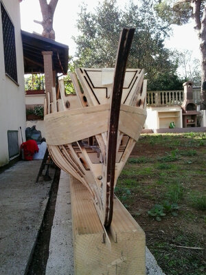
Inserisco anche le immagini del primo fasciame.
Slats di legno di tiglio spessi 0.5 mm.

Queste che vedete per ultimo sono, invece, le immagini di un "truschino" .
Questo "truschino" (non so come tradurlo in inglese) è fatto da me. Ho preferito farmelo da solo invece che comprarlo.
Se avete capito di che cosa si tratta, aiutatemi a tradurlo. Che termine usate?
Serve per tracciare la linea di galleggiamento.
In questo caso l'ho usato per tracciare le varie linee d'acqua su un foglio.
Questo procedimento empirico mi è servito per rilevare e poi correggere alcune piccole imperfezioni a prua.
Quando avrò tempo correggerò anche il progetto 3d in Rhinoceros.

ll regolo di legno (quadrello di legno) che vedete sopra alle ordinate serve come ulteriore allineamento delle frames.


Good evening to all modelers.

I forgot to show the keel, I couldn't make it in one piece.
Here she is attached.

I also insert images of the first planking.
0.5 mm thick lime wood slats.
The wooden ruler (wooden square) that you see above the frames serves as a further alignment of the frames.

These that you see last are, however, the images of a "cushion".
This "cushion" (I don't know how to translate it into English) is made by me.
I preferred to make it myself rather than buy it.
If you understand what it is, help me translate it. What term do you use?
It is used to trace the waterline.

In this case I used it to trace the various water lines on a sheet of paper.
This empirical procedure helped me detect and then correct some small imperfections on the bow. When I have time I will also correct the 3D project in Rhinoceros.
When I have time I will also correct the 3D project in Rhinoceros.
The wooden ruler (wooden square) that you see above the frames serves as a further alignment of the frames.


n.jpg

primo fasciame.jpg

primi listelli.jpg

scafo primo.jpg

truschino.jpg

linee d'acqua.jpg
 
These that you see last are, however, the images of a "cushion".
This "cushion" (I don't know how to translate it into English) is made by me.
I preferred to make it myself rather than buy it.
If you understand what it is, help me translate it. What term do you use?
It is used to trace the waterline.
I would call it a waterline marker jig. If you refer to those apparently foam parts, assuming you use them to get the waterline marker at the right height, I would refer to it as spacer.
 
Back
Top