You are using an out of date browser. It may not display this or other websites correctly.
You should upgrade or use an alternative browser.
You should upgrade or use an alternative browser.
Kingfisher 1770 1:48 POF
- Thread starter dockattner
- Start date
- Watchers 109
- Joined
- Oct 23, 2018
- Messages
- 537
- Points
- 353

I would use treenails for the keel and stem parts and also for the frames. For a sloop 6 nails are common for the keel parts. David shows the position for the treenails at the frames in his book. There is one bolt in the centerline which goes through the keelson to the frames. Further you can show 8 treenails at the side for the connection of the keelson parts.Good thoughts Christian. Unless I read wrong, bolts were common on the centerline framing and then treenails in the frames?
I hope I've nothing forgotten.
Wonderful work Paul and a pleasure to follow your build. There’s some very interesting questions, observations and knowledgable advice already.
This piece (stern deadwood) was almost the end of me: tapered top to bottom and also front to back - and then notched to receive the aft cant frames. But the kit design made this something even a relative newcomer could accomplish with careful chisel work and sanding blocks. Well done, LSS and Mr. Hunt.
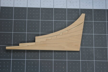
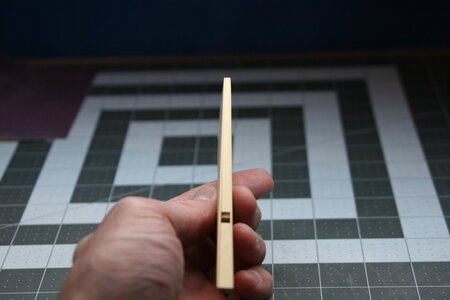
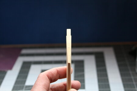
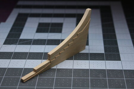
The top to bottom taper should be more concave but I'm hoping this will still work. Thanks for stopping by!


The top to bottom taper should be more concave but I'm hoping this will still work. Thanks for stopping by!
- Joined
- Sep 3, 2021
- Messages
- 4,296
- Points
- 688

Time for some CNC-equipment?The top to bottom taper should be more concave
I wouldn't be able to tell whether the taper should be more concave or convex, so I'm convinced...
This part looks very nice and sharp, Paul. Well done.This piece (stern deadwood) was almost the end of me: tapered top to bottom and also front to back - and then notched to receive the aft cant frames. But the kit design made this something even a relative newcomer could accomplish with careful chisel work and sanding blocks. Well done, LSS and Mr. Hunt.
View attachment 353124
View attachment 353125
View attachment 353126
View attachment 353127
The top to bottom taper should be more concave but I'm hoping this will still work. Thanks for stopping by!
Regards, Peter
Extremely good work Paul !!
Kind Regards
Nigel
Kind Regards
Nigel
Good morning Paul. Your work is soooo good.! I see what you mean re the tapering. I think the fact this is macro the convex may be exagerated.You are talking minute margins for sure. Unfortunally when you build a POF ship minute margins make a difference so I hope this works for you. Now you know why Im still on POB kitsThis piece (stern deadwood) was almost the end of me: tapered top to bottom and also front to back - and then notched to receive the aft cant frames. But the kit design made this something even a relative newcomer could accomplish with careful chisel work and sanding blocks. Well done, LSS and Mr. Hunt.
View attachment 353124
View attachment 353125
View attachment 353126
View attachment 353127
The top to bottom taper should be more concave but I'm hoping this will still work. Thanks for stopping by!
 . Cheers Grant
Thank you kindly, gentlemen, for the encouraging posts and likes. I've decided to refine the tapering a bit more in order to get me closer to the build requirements found in TFFM.
A passing observation from my experience using this series of books thus far: the measurements provided in the text are generally given full-size and in the imperial system. For example, for the stern deadwood I am told to make the width at the bearding line (basically where you see the notched area for the frames to seat into) 15 inches and then taper down to 5 inches at the bottom where the deadwood joins the keel.
By using actual measurements from a full-sized ship this allows the book series to accommodate every modeler's preferred scale. Makes perfect sense, right?
Well, this creates all sorts of tripping-up points for me because I think in metric (Why, you ask? Because I can picture 2.6 mm in my mind but not .104 inches). This means I need to first convert inches into mm and then adjust for my scale (1:48). Of course, the math isn't hard, but it all introduces room for mistakes to be made. I find myself constantly checking and recalculating things over and over again. I can't tell you how many times I've said to myself: how can you be so dumb?
When my dad was frustrated with me he used to say, "you've the dumbest smart kid I ever met." I didn't like that very much - but it seems he may have been right .
.
A passing observation from my experience using this series of books thus far: the measurements provided in the text are generally given full-size and in the imperial system. For example, for the stern deadwood I am told to make the width at the bearding line (basically where you see the notched area for the frames to seat into) 15 inches and then taper down to 5 inches at the bottom where the deadwood joins the keel.
By using actual measurements from a full-sized ship this allows the book series to accommodate every modeler's preferred scale. Makes perfect sense, right?
Well, this creates all sorts of tripping-up points for me because I think in metric (Why, you ask? Because I can picture 2.6 mm in my mind but not .104 inches). This means I need to first convert inches into mm and then adjust for my scale (1:48). Of course, the math isn't hard, but it all introduces room for mistakes to be made. I find myself constantly checking and recalculating things over and over again. I can't tell you how many times I've said to myself: how can you be so dumb?
When my dad was frustrated with me he used to say, "you've the dumbest smart kid I ever met." I didn't like that very much - but it seems he may have been right
 .
.
Last edited:
- Joined
- Oct 23, 2018
- Messages
- 537
- Points
- 353

If you have Excel or another spreadsheet program, it's very easy to make a sheet with a all the necessary calculations.
I've prepared me an Excel sheet to calculate the values in scale 1/36 and 1/48 every 0.1'' of the original ship
I've prepared me an Excel sheet to calculate the values in scale 1/36 and 1/48 every 0.1'' of the original ship
- Joined
- Jan 9, 2020
- Messages
- 10,378
- Points
- 938

I understand exactly where you are coming from. I grew up in the metric era and inches to me are a proper PITA. Your work though looks beautiful, Paul. Just take your time, check and re-check; then we can't be too dumb,Thank you kindly, gentlemen, for the encouraging posts and likes. I've decided to refine the tapering a bit more in order to get me closer to the build requirements found in TFFM.
A passing observation from my experience using this series of books thus far: the measurements provided in the text are generally given full-size and in the imperial system. For example, for the stern deadwood I am told to make the width at the bearding line (basically where you see the notched area for the frames to seat into) 15 inches and then taper down to 5 inches at the bottom where the deadwood joins the keel.
By using actual measurements from a full-sized ship this allows the book series to accommodate every modeler's preferred scale. Makes perfect sense, right?
Well, this creates all sorts of tripping-up points for me because I think in metric (Why, you ask? Because I can picture 2.6 mm in my mind but not .104 inches). This means I need to first convert inches into mm and then adjust for my scale (1:48). Of course, the math isn't hard, but it all introduces room for mistakes to be made. I find myself constantly checking and recalculating things over and over again. I can't tell you how many times I've said to myself: how can you be so dumb?
When my dad was frustrated with me he used to say, "you've the dumbest smart kid I ever met." I didn't like that very much - but it seems he may have been right.
I am a big fan of your work - and maybe get a big fan also for this kit
- Joined
- Oct 23, 2018
- Messages
- 537
- Points
- 353

I am a big fan of your work - and maybe get a big fan also for this kit
The kit has only one big problem, what I discussed with Paul already. The frame design from Cygent which Bob has used to produce the kit is not correct for the Kingfisher. If you have a look at the available original drawings you can see that Kingfisher has double frames in the midship area. The new design is only valid for the newer ships of the class.
Phoning a friend... Topic: rabbet at the sternpost.
In the LSS instructions it says the rabbet transitions above the bearding line from a shallow V and ends in a U - but TFFM seems to say the rabbet remains a shallow V above the bearding line.
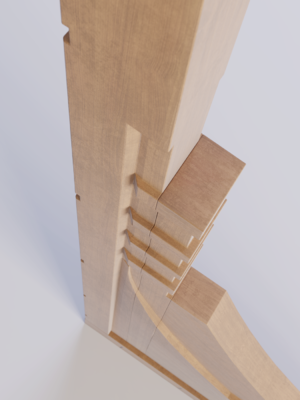
Should the rabbet be more of a U near the top (unlike what is shown in this 3D graphic image)? That would seem to make more sense...but...
In the LSS instructions it says the rabbet transitions above the bearding line from a shallow V and ends in a U - but TFFM seems to say the rabbet remains a shallow V above the bearding line.

Should the rabbet be more of a U near the top (unlike what is shown in this 3D graphic image)? That would seem to make more sense...but...
Last edited:
- Joined
- Oct 23, 2018
- Messages
- 537
- Points
- 353

Wow, this is a beautyful stem. Are there more pictures of the model available? The transition of the rabbet looks good.
Are you modeling now on a computer and make a virtuel model?
It is not a real photo of your wooden model stern post, or?
It is not a real photo of your wooden model stern post, or?
That was also my thought by the last picture.Are you modeling now on a computer and make a virtuel model?
It is not a real photo of your wooden model stern post, or?
Regards, Peter
Last edited:


