tug boat ALVA B

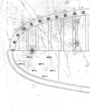
I know that tugs can sink the stern when they are pulling real hard. I wonder if this is a way of getting rid of the water although you'd think there would be better methods.

once again Don you are on the right track here is an answer i got off facebook

The raised deck covers the rudder quadrant (the two rail-like things leading to it from the rear of the cabin are covers for the steering chains). There would be hinged/removable panels to access the rudder quadrant. Also, you could often see the towing hawser coiled up on top of it when not in use, so the slots are to allow water to drain away from a wet hawser.

1662129566888.png
 
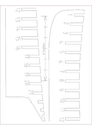
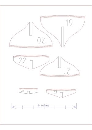
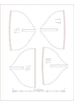
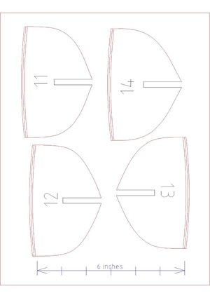
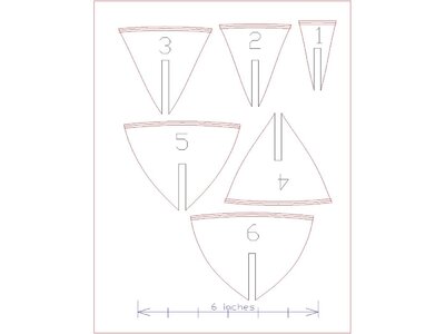
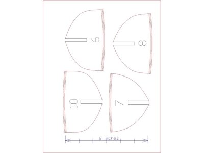
here are 8 1/2 x 11 printable set of bulkheads and a profile for the hull

for some reason sheets 1 and 2 did not convert from DWG to a JEPEG so i have to look into that

i also posted PDF files that should print. Print a sheet and check the size there is a 6 inch scale on each sheet

there are 3 deck lines on the bulkheads the top line is the deck the one under the top is the deck planks and the botton line is for adding a false deck.

The problem with adding a 1/8 plywood false deck is bending the sheet from stem to stern and also bending it side to side.

what i would do in this case is either filling the spaces between the bulkheads to create a solid surface for the deck and hull planking or plank the deck with 1/8 thick material and sand the deck down.

profile-page-001.jpgbulkhead_sheet5-page-001.jpgbulkhead_sheet4-page-001.jpgbulkhead_sheet3-page-001.jpg
 

Attachments

  • profile.pdf
    22.4 KB · Views: 7
  • bulkhead_sheet5.pdf
    24.6 KB · Views: 6
  • bulkhead_sheet4.pdf
    16.8 KB · Views: 6
  • bulkhead_sheet3.pdf
    16.3 KB · Views: 5
  • bulkhead sheet2.pdf
    30.4 KB · Views: 3
  • bulkhead sheet1.pdf
    28.3 KB · Views: 4
Last edited:
In the past, to alleviate trying to force a heavy sub deck material to follow the lines of the tops of the bulkheads I added a little extra materiel to the tops. In this case I would add !/16th to the top of the bulkheads, lay a 1/32 plywood sub deck, and finish off with a 1/32 inch cherry planking. These excellent drawings makes me think I need another tug boat in my collection.
 
Thanks for the info 3 hours of tracing and cutting and sanding, 6 bulkheads done and now you tell me my model is going to be an 1/8 inch too tall or I can add a false deck in between the bulkheads would also work?? or could use 1/32 plywood as a false deck, I think using 1/4 spacers of some soft wood in between the original would be easier to follow the camber of deck?? bill s.
 
In the past, to alleviate trying to force a heavy sub deck material to follow the lines of the tops of the bulkheads I added a little extra materiel to the tops. In this case I would add !/16th to the top of the bulkheads, lay a 1/32 plywood sub deck, and finish off with a 1/32 inch cherry planking. These excellent drawings makes me think I need another tug boat in my collection.
 
In the past, to alleviate trying to force a heavy sub deck material to follow the lines of the tops of the bulkheads I added a little extra materiel to the tops. In this case I would add !/16th to the top of the bulkheads, lay a 1/32 plywood sub deck, and finish off with a 1/32 inch cherry planking. These excellent drawings makes me think I need another tug boat in my collection.
 
I agree, filling the spaces in between the bulkheads is a great way to add extra glueing surface for a sub deck or final planking. Depending how close my bulkheads were to each other I have done it both ways. Regardless which way I use, my bottom line has always been use 1/32 ply for my sub decks and plank on top of it. Do you plan to make your tug RC? Jim
 
dear fourseas: how funny we thought nearly the same thing at nearly the identical time,, I already started to cut bulkheads last night, hate to waste the time I might try the keel today because it's raining I believe I CAN DO THIS DO THIS!! I think filling them in might prove easier than bending a false deck in two planes Bill s.
 
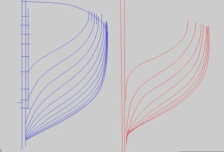
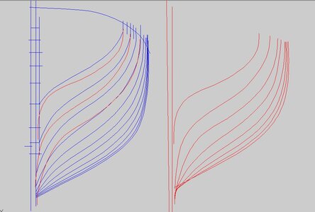
i have different sheets of plans that give me different hull shapes you can see the difference in the two drawings

bp2.JPG

when i place the red station lines over the blue bodyplan at some point along the way someone changed things

bp1.JPG
 
i based the shape of the bulkheads on the blue bodyplan i figured that was the final drawing used to lift off the frame shapes, the red bodyplan was taken from a half model so it was apparently refined to look like the blue bodyplan.

it is also confusing because the blue bodyplan was drawn with a level keel and the red bodyplan was drawn with a level waterline.

so the Alva is drawn 2 ways one for framing the hull and one for all the deck and cabin work.

interesting

was the Alva built on a level keel and all the frames perpendicular to the level keel? if so there would be a slight slant to the frames when the hull was floating. So once the hull was framed up and planked the Alva B could have been launched and the rest of the structure from the deck up was built as the Alva B was floating on a level waterline.
 
Last edited:
Dave ; You are the most meticulous I think the red ones create a more knife edge keel and floating higher hull (broader surface area), I was going to build it with the slanting keel, I think the spacers in between the bulkheads are 5/8 wide say by 1/4 to give you some sanding room, Can you make me some soft wood (basswood?) 5/8 x1/4 let me set up the bulkheads after I finish them and maybe I could stop by to pick them up and show you what I have got done, Holiday rain makes this a great hobby,, Bill s.
 
here is some general information


Old steam tugs often have crew bunks because they typically ran 24-7. They were needed/used much more frequently back then.
Starting a steam tug takes a bit of time (have to fire the boilers, build pressure, oil engines and etc.) It's a lot different
than a diesel that can be ready to work in relatively short time. So, to be responsive, once the boilers are lit in the spring,
they're typically kept lit and the pressure maintained until they shut them down for winter. So, someone needs to stay on board
for extended periods. The old Edna G. has 4 bunk beds beneath her fantail, two more in her forepeak for the captain as well as a
galley and mess. She also has a head.


Steam tugs always at the ready would have crew on board for long spells. This tug appears to have a separate steam exhaust pipe behind
the stack - some older arrangements had no condenser to return the exhaust steam to boiler feed water. A condenser could be a mechanical
drawback for alll the maneuvering. The boiler also has a large steam dome, to give a ready supply. That big single cylinder would gulp steam
- maybe Clyde puffer-like noises from that exhaust


I’m having a hard time understanding that boiler. It seems like the grate is ahead of the boiler. I also don’t understand the engine,
is it a single expansion?

Single expansion non-condensing, I'd guess - the boiler may be Scotch type with the return flue, so the blue area is the furnace itself
with the stokehold and furnace doors on the right. The horizontal separation between the furnace and the stack isn't shown I guess.
The non-Scotch boiler feature would be that giant steam dome.

definitely odd.


I recall reading about old tugboat boiler explosions caused by boiler "panting". The big single cylinder's action would cause the boiler
to pulse and lead to cracking along the seams. Quite chunky timber around the thrust block supports too.

"Tugs are not meant for long stays out so there is no need for crew quarters."
I'll have to tell that one to my friends who work in the towing business.

Minimum 5 men on a watch more likely 6 to 8 man crew.
 
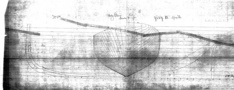
Union dry Dock in Buffalo were building tugs one right after another. It is possible they had one or two half hulls that were the "generic" shape of a tug hull. When a new tug was started the generic hull was tweaked. On one of the drawings did say from a model. The final bow and stern of the Alva B is different from the original model lines.

the first drawing is noted from a model

Line-Profile model.jpg

this drawing says bodyplan Alva B and it does not match the top drawing, close but not the same. My reasoning is the bottom drawing is the final, for one thing all the frame shapes are drawn and you would not do that on a first draft.


Line-Profile model2.jpg
 
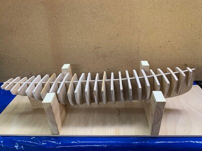
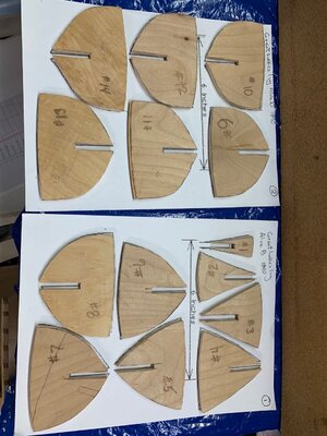
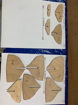
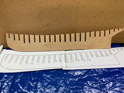
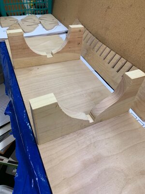
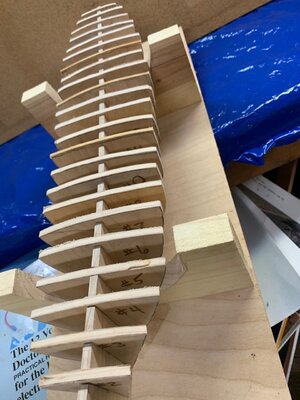
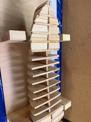
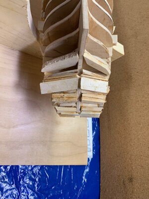
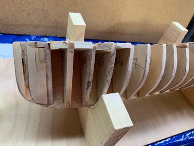
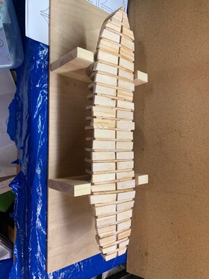
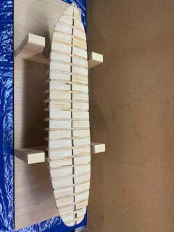
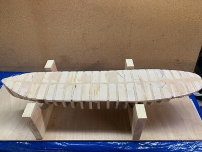
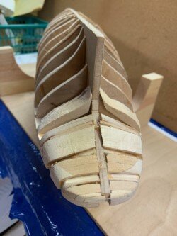
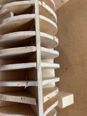
Hello Dave and other nautical carpenters, with the bad weather I decided to get started with the original drawings 2 weeks ago got the original drawings enlarged by 308% so that the 6 inch line would be really 6 inches, so here is the start, I plan to fill in the deck portion of the bulkheads to improve the deck surface, I think the extra 1/8" will give me some bulk to refine the deck slope and camber before planking, I'm planning on building it with some slope to the keel, I'm now starting to block in the bow with some scrap basswood and gluing the other bulkheads, Once glued and deck supported I believe to fair the bulkheads and fabricate a keel with a rabbit for the planking of the hull. hopefully some advice from the gallery would be helpful on this scratch build But I believe there are enough original plans to make this model a reality,, Bill s.

thumbnail_IMG_2082.jpg

thumbnail_IMG_2087.jpg

thumbnail_IMG_2089.jpg

thumbnail_IMG_2091.jpg

thumbnail_IMG_2095.jpg

thumbnail_IMG_2085.jpg
 
just finished getting the false deck boards fitted and glued, added some scrap lumber to the bow and stern for more surface area for the planking , will try to get some new pics after the sanding and shaping of the deck contours, Bill S
 
Back
Top