tug boat ALVA B

Hi Dave,

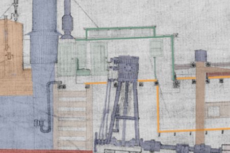
My guess for the aft small funnel is engine/steam exhaust maybe they weren't running a condenser.
As for the forward light tan items they look a bit like bunks, but you wouldn't expect bunks in a harbor tug I would think.
Hopefully you will get answers to your questions.

Cheers,
Stephen.

i am also on a steam engine forum and these guys are the experts
your right it is a steam exhaust

i agree bunks on a harbor tug seems out of place.

for those folling the plan development here is an up date
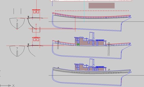
up date 8 21.JPG

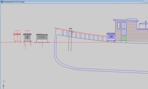
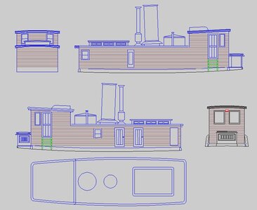
at the bottom is the outside profile
above that is the inside profile in progress without the bulkwark in the way you can see the full cabin down to the deck.
remove the cabin and the top is the cap rail line, stanchions and the deck line. With those references i started a front view of the wheelhouse, that is what is going on at the left.

in the top drawing the vertical red line is bulkhead 7 right at the front of the wheelhouse.

missing in the drawings is the companion way in front of the wheelhouse. Thats because i did not know what is was at first.

the Alva had sisters and the Alva is #54
searching plans sometimes the ID of the plan is a number like #54 or #44

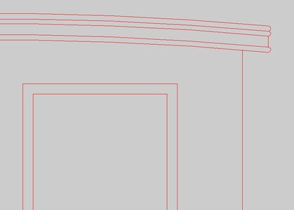
about that whining about the molding well
i found a drawing showing the cabin roof molding so i was able to recreate it, it looks like this
up date 8 21aq.JPG
 
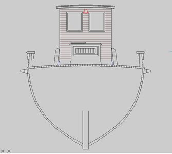
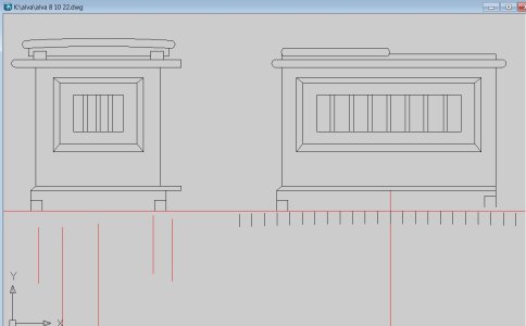
the front view of the wheelhouse is done
interesting hull planking at the keel there is a wide and thick garboard plank then a run of wide bottom planks, at the turn of the bilge the planks get narrower and finally at the sides the planks are the narrowest. the deck planks are actually not a plank they are 3 x 3 inch timber.

Today i will draw the back view of the cabin and wheelhouse

wheelhouse front.JPG
 
way back when i started out in the graphic arts i use to be a table top draftsman that is with a T square, triangles and things like a compass, pen and ink. i even had to go analog and use a steel ruler where i had to read and mark out points. My digital ruler is quite different. All i need to do is type the start and finish and the angle. I wondered how those shipwrights could build a ship with no plans, now i know it is all about the numbers and entire ship can be recorded in a note book of numbers.


Back then to do the rear view i would have to use mylar and trace the wheelhouse or project points from one view to another. With CAD all i need to do is select, copy and paste the front view and make the changes for a rear view.

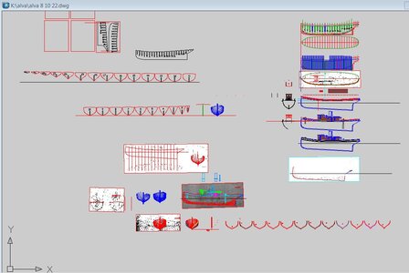
This is the working file, at the top are the bulkheads which will be copied and arranged in the red squares which are 8 1/2 x 11 and printable with an average printer. At the bottom each frame is being drawn out for a timbering model with all the frames and hopefully a 3D printed steam engine

full drawing.JPG
 
Last edited:
Nice work Dave, your drawing is very well organized and looks good.
 
thanks mike

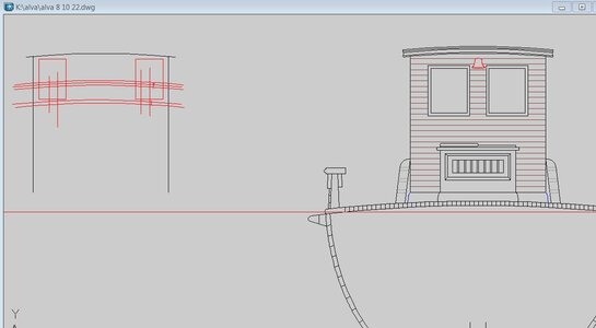
for the rear view i set up the drawing

project locations from the front view
top black line bottom of wheelhouse roof
red boxs are windows
tripple arc lines roof of skylight
bottom 2 red lines roof of cabin
bottom red line deck

back cabin1.JPG

as for the details of what the back wall looked like, take a guess!

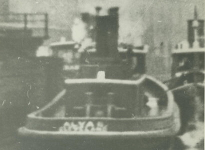
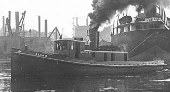
this is a low resolution of the Alva B so i Emailed the source and asked if there was a high resolution image available. If there is i can play with the image in Photoshop and see if i can pull out any detail. But this might take days or weeks or just cost to much to get an image or there isn't a high res image.

if nothing comes of this my guess is looking between the two posts there is an ever so slightly darker square, you have to look a few times to see it, that might be a window.

back cabin bigger.jpg
 
finding information on the steam engine is going to be a rough job. finding an actual drawing will be even harder


Registry and Rig Information
Vessel Name: ALVA B.
Nationality: U.S.
Official Number: 106738
Rig: Tug
Dimensions and Tonnage
Length: 73.50
Width: 18.42
Depth: 10.50
Masts: 0
Gross Tonnage: 83.00
Net Tonnage: 41.00
Hull Material: Wood
Hull Number: 00054
Vessel History
Rebuilds:
History:
Disposition: Foundered November 1, 1917 off Avon Point, OH, Lake Erie; no lives lost. Had reportedly lain for some time at Sandusky, OH,
and had dried out.
Build Information

Builder: Union Dry Dock Co.
Place Built: Buffalo, NY
Year Built: 1890
Ownership Changes

Owner Date Registry Official Number
Vessel Owners' Towing Co. 1890 - 1899 U.S. 106738
Great Lakes Towing Co. 1899 - 1914 U.S. 106738
H.S. Kerbaugh, Inc. 1914 - 1917 U.S. 106738
American Towing Co. 1917 - 1917 U.S. 106738
Name Changes

Name Date Registry Official Number
No name changes recorded.

tugs by Union Dry Dock. The Alva B had a 22" bore x 24" stroke, 425 hp 2 120 rpm, HPNC (High Pressure Non-Condensing)
engine built by Whitman Co., Buffalo, NY and a 8'2" x 15", 140 psi, firebox boiler, built by Lake Erie Boiler Works, Buffalo, NY.
Of the 11 tugs built between 1888 & 1893, 10 had HPNC engines of which 9 were built by Whitman Co. All but two of the 11 firebox
boilers came from Lake Erie Boiler Works.
 
i figured it out

why the plan is drawn with a window in the side of the cabin

cabin side.JPG

and why the photo shows a door?


alva b1_edited-1.jpg

on the plan your looking through the cabin at the inside of the wall on the other side, in the photo your looking at the outside of the cabin
the back wall will have to be a fill in the blank


i know Buffallo Dry Dock built 14 of these tugs between 1878-ish to 1889- ish at the rate of one or two every year for 10 years and plans of them all survied or for the most part 61 drawings in total of all 14 tugs. By taking all the plans and combine them you can see the how these where built. A detail left off one drawing may be on another. In the collection of drawings one may have the back wall of the cabin.
 
Do you have access to all 61? Low or high res.? I never thought it might be a problem to be overwhelmed with drawings :) :) :)

that is a no and a yes

NO even though i live within driving distance to the Bowling Green library and archive i can go there and seasrch through thousands of holdings in the archives. That would take a day or two and an over night stay in the area. So adding up hotel costs, gas costs, eating cost and time, it is adding up to hundreds of dollars for a research trip.

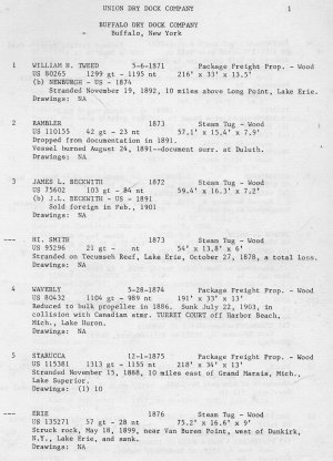
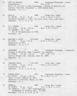
YES i have access to the archives through the website, they do not list all the drawings or what drawings are available to what ship. what i have is the MS-212 a inner library publication listing of all the drawings. it is what was called the orange book OR
Naval Architectural Drawings
American Ship Building Co. & predecessors 1867 - 1920
Center for archival collections MS 212

the book lists each ship builder and all the ship built in the yard
the numbers after DRAWINGS: 1 through 10 are the type of drawing like inside profile or deck etc

having the listing i then email Mark who is the archivest at Bowling Green and give him the exact info like

listing #54 ALVA B plan #3 and he will send me a high res TIFF file


planlist1.jpg

planlist2.jpg
 
once i get all the main parts of the drawing done then i will go back and add smaller details, cross section drawings, construction drawings etc.

As i draw the tug i am seeing interesting things like you can not go from the bow to the stern below deck. The hull is divided into 3 parts the bow area, i do not think is a crew quarters it is where all the tow ropes and cables are stored. This area is sectioned off by a wall below the wheelhouse. The the engine and boiler area only way down is a throught a door in the side of the cabin and down through a small hatchway. One third of the area below deck is all engine. At the stern the cabin is another storage area. I did notice the floors in the bow and stern have a slant. So i was told that is to let the water from wet rope and cable to drain so the rope does not sit in a puddle of water. I don't know if that is true or not. You can accomplish the same thing by leaving a small space between the floor boards.
 
and now for the deck

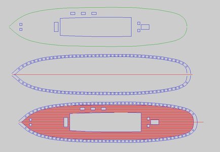
the first drawing is a pattern for a plywood sub deck the center is the cabin area aft is a skylight and bit posts, forward is the companion way and 2 more posts.

drawing below that is a pattern for the waterways, a tricky piece to fabricate if you are going to set in the bulwark stansions you will need to cut a lot of square holes.

and the last drawing shows the decking and waterways the deck is covered with 3 inch square pieces so there are a lot of them.

the drawings are being done for plank on frame with deck beams. As a plank on bulkhead model with a sub deck the bulkheads will need to be modified. With a plywood sub deck and planked with 1/16 decking the deck will be to high.

deck.JPG
 
Hello Dave: Were the plans I dropped off the same as yours or length side view different? Just wondering? Bill S. Hope the can help, Sorry I missed you,,
 
i have scan of the same plans but looking at a scanned image you can not zoom far enough in befoe the image begins to break up Seeing the paper plans i can see more details.
 
Last edited:
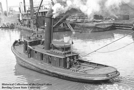
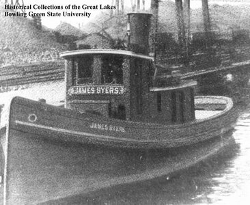
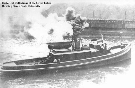
another question i see all tugs have a raised deck at the stern

michigan.jpgbyers.jpgday.jpg
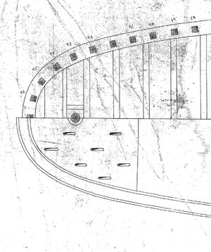
the drawing of the Alva shows the raised stern deck but there are slots or something drawn on the deck, anyone venture a guess as to what they are?

stern deck.jpg
 
Bill dropped off a set of plans which i am now able to see more details. I could zoom in only so far on the large scans now i can scan in high resolution

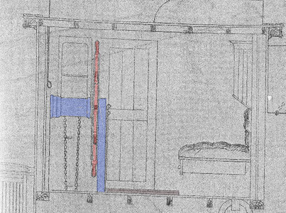
wheelhouse.jpg

inside the wheelhouse i can see the wheel the mount and the stearing chain along with a platform at the wheel


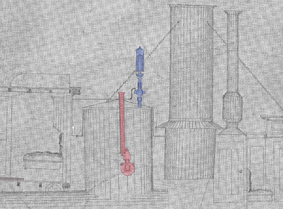
stack.jpg

behind the wheelhouse there is the boiler then the blue steam whistle smoke stack and a steam stack. I do not know what the red pipe is but i will find out.
 
Last edited:
I know that tugs can sink the stern when they are pulling real hard. I wonder if this is a way of getting rid of the water although you'd think there would be better methods.
 
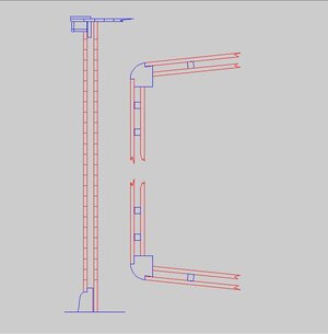
as the drawings develope more and more details are added, here is a construction drawing of the cabin walls. Top view the corner are a beam with the outer corner rounded and the siding is set into the beam.

side view shows the outer siding sits on top of the waterway and the inside siding sets against the inside face of the waterway, at the top is the built up roof molding

cabin walls1.JPG
 
Back
Top