The fluyt by Åke Rålamb 1691 – Dutch bottom-first graphically

Joined
Apr 26, 2023
Messages
383
Points
323

Location
European Union
.​

The first attempts with the 3D reconstruction model are coming out very well, so I think the thread can now be started. Why should they not come out? The method is so easy and even fool-proof that small children could manage it.

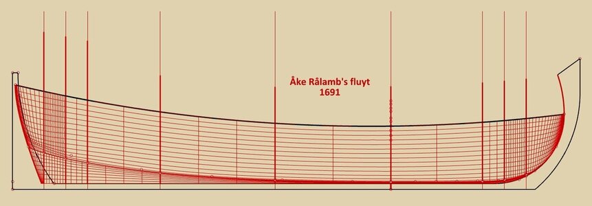
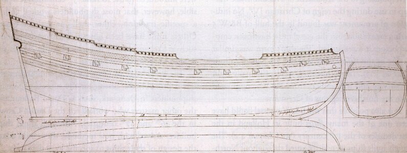
But to the point. The fluyt from plate G in the work Skeps Byggerij 1691 by Åke Rålamb, is a highly specialised type of merchant ship widely used in a number of variants. This one is 130 feet long and 28 feet wide (L/B = 4.64:1) and has characteristics typical of vessels sailing in the northern waters of the continent (Fig. 1).
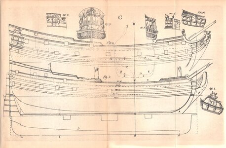

Skeps Byggerij - Tafl.G.jpg


In design terms, the drawing itself can be interpreted in several ways. For the main presentation, I have chosen a non-graphical variant of the bottom-first method, that is, one that does not require prior plans on paper before actual construction. Of course, there is nothing to prevent such a draught on paper, at least partial, being made, either then or today. Mais pourquoi le faire du tout? Basically, the method shown will be very similar to the one presented in the thread on the boyer from the same work by Åke Rålamb. The only significant difference comes down to the slightly different positioning of the hanging guide rails, i.e. by means of a beams attached to the ship's posts, as shown in the figure below.

001.jpg


The construction sequence will not be described in its entirety, as this is already very well presented in the existing literature. While Witsen's base work is rather too hermetic to be consulted directly, the indispensable Nicolaes Witsen and Shipbuilding in the Dutch Golden Age by Ab Hoving can be particularly recommended, and on a archaeological level, for example, the excellent The Renaissance Shipwrecks from Christianshavn by Christian Lemée.
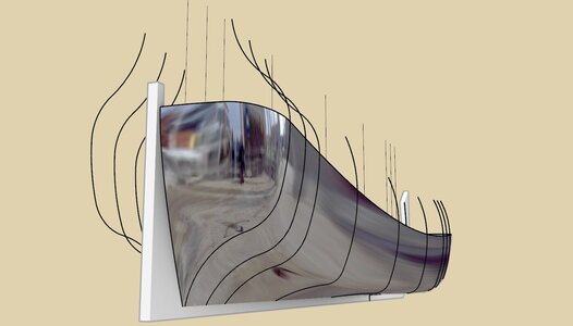
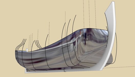
ViewCapture20230801_024419.jpg


ViewCapture20230801_024543.jpg


ViewCapture20230801_024648.jpg


ViewCapture20230801_025109.jpg

.​
 
Last edited:
.​

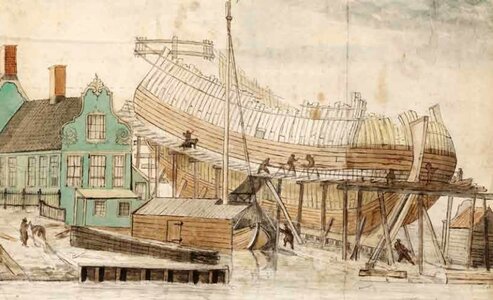
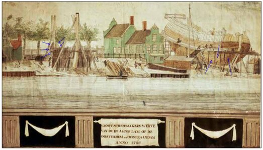
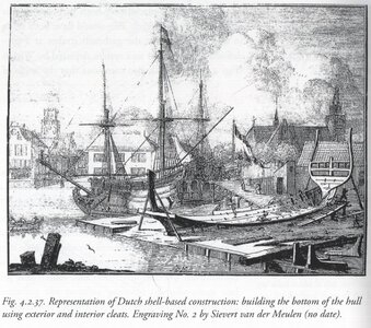
And there is another and rather little known, yet important engraving from the period, just kindly provided by Ab. It is particularly interesting, as it shows horizontal beams at both ends of the hull under construction, and at several levels. Acting perhaps as a support for scaffolding, but possibly also for hulls of more complex shapes, as opposed to boxy fluyts. Many, many thanks Ab.


scheepswerven-2 (2).jpg

.​
 
Last edited:
Hi Waldemar,

Good to see the first steps on the fluyt.
I am very curious about what you can find about the radius of the bilge and the shape of the futtocks and change a of the futtocks over the length of the hull.
The use of a rope to determine the curvature of the wale looks very interesting and something I can certainly use "test" in the build of my model.
 
Last edited:
.​

And there is another and rather little known, yet important engraving from the period, just kindly provided by Ab. It is particularly interesting, as it shows horizontal beams at both ends of the hull under construction, and at several levels. Acting perhaps as a support for scaffolding, but possibly also for hulls of more complex shapes, as opposed to boxy fluyts. Many, many thanks Ab.


View attachment 387676

.​
Hi Waldemar, the thing with this engraving is that it shows three ships which appear not being build using shell first but more like ships build at the Maze "Rotterdam" or Zeeland area frame first with the use of "centen"
 
.​
Hi Waldemar, the thing with this engraving is that it shows three ships which appear not being build using shell first but more like ships build at the Maze "Rotterdam" or Zeeland area frame first with the use of "centen"

Rightly Maarten, thanks for your input. However, my main point was to show that in general it was quite routine to use these crossbeams, and that they were quite multipurpose in nature. Just with different examples and in different applications. Besides, without going into details, I guess one could also say that both methods, i.e. described by Witsen and van Yk, were already generally skeletal after the 'flat' and bilge strakes had been laid (in bottom-first method), so various similar 'tricks' were possible in both of these methods. And, I simply chose this figure as well, because it is particularly didactic, or, in other words, to familiarise readers with their apparently widespread use.

At least such was a general idea. :)

I think I will still add to or modify my description to make it clearer.

Many thanks.

.​
 
Last edited:
.​

What I see here, is clearly shell-first building.

Yes, and at this late date it is even surprising for such large units. Although I heard recently that even today shipwrights still use this method to build small vessels, and that's only a few dozen kilometres from where I live! I'll have to go there.

But if you want to suggest something specifically, please go ahead, otherwise I might not be able to guess and respond. Besides, I've already found hints from other participants to be very beneficial more than once. Kindness or gentleness won't bother me as long as they don't replace openness. :)

.​
 
.​

Well, I still do not understand. Whom do you cite? And why? This is not my statement...

.​
Calm down, please, there is no why. I just expressed a thought concerning that engraving, nothing more.
 
.​

@ara

Indeed, a great book. I have both versions, that is the Dutch-language one and its English translation. But I don't remember being involved in its writing, unfortunately, and my name is certainly not on the list of its authors. Can you please edit your post accordingly indicating the actual author? Thank you.

.​
 
.​

Ah, yes. Indeed a little confusion has arisen, as sometimes it is difficult to discern the meaning. Thanks.

In addition to the Rålamb's fluit, I'm also keen to take a simultaneous look at some other ship(s) with similar characteristics, and from an earlier period. For several reasons: to test the method's feasibility for a slightly different form, to demonstrate the flexibility of the bottom-first method, to see what a Dutch shipwright would have achieved by building a ship based on a design à la anglaise (which routinely happened in Denmark at the time), that is also my most favourite period.

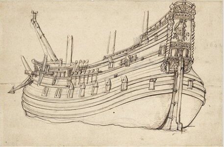
For example, this Danish defensionsskib, a hybrid of a fluit and a warship, designed by David Balfour in 1630 and built by various shipwrights to the number of 30 (Danish archives, E8).


Defensionsskibe 1630.jpg


I would expect to get a general appearance like in this 1642 van de Velde engraving, sporting somewhat rounder bow and stern shapes than seen in 'typical' designs known from later period (NMM).


fluita 1642 - NMM.jpg

.​
 
Last edited:
.​

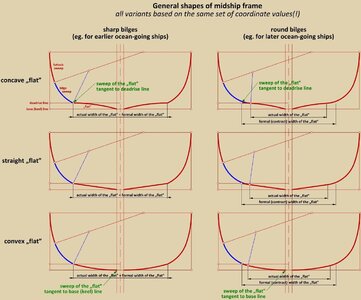
The essence of the method presented is primarily based on the assumption that the actual width of the 'flat' does not necessarily equal the formal width of the 'flat'. By 'formal width' it is meant the width used to design the shape of the frame, and as such assumed to be also given in shipbuilding contracts and at least on some surviving period plans as well. By contrast, the 'actual width' is the result of a possible truncation of the formal width of the 'flat' by the bilge sweep.

The reason for this actual shortening of the 'flat' may be primarily due to the use of round bilges by the shipwright, or, in geometrical terms – making the bilge sweep tangent to the curve of the 'flat'. While the theoretical/formal width obviously remains necessary, the outer, physical edge of the 'flat' planking may actually be reduced by the bilge sweep in variants sporting round bilges. This is shown in the diagram below.

In addition to this, it is shown below how very different midship frame shapes can be obtained by using identical(!) co-ordinates, taken, for example, from some contract or written specification. These kinds of 'subtleties' are actually no longer described in the treatises of the period, but are clearly suggested above all by the archaeological material and at least some of the surviving plans in graphic form. This state of affairs, on the one hand, makes graphic reconstructions on the basis of written specifications (as found in a very large number of surviving contracts) more difficult, by multiplying the number of possible variants, on the other hand, however, can perfectly explain all sorts of apparent mere anomalies (eg. apparent inconsistency of written specifications with plans of Danish Hummeren 1623 or French 1686 design of a frigate by Chaillé).


ViewCapture20230802_181521.jpg

.​
 
Last edited:
.​

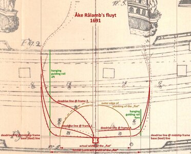
As if to illustrate, so to speak, and to verify the presented method on a concrete example, below is an additional diagram comparing the contours thus obtained to the contours of the frames on the original draught from Rålamb's work. In addition, an outer edge of the physical planking of the 'flat', as seen in the end-on view is also marked with a brown line. If this is a circle, delineating the equal width of this planking, then, apart from the aft section, it corresponds quite accurately to the geometrically correct actual width of the 'flat' on all frames.

It should also be added that the run of the hanging guide rails (green) in the vertical plane is perfectly straight, which is a dream circumstance for the eventual shipbuilder. Equally important, in the proposed method there is no need to calculate the cross-sectional radii of the 'flat' at all, and perfect, variable radius contours are obtained along all the length of the hull anyway.


ViewCapture20230803_111042.jpg

.​
 
Last edited:
.​

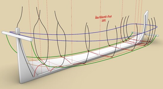
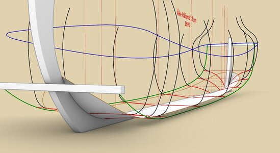
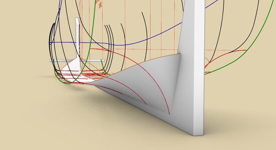
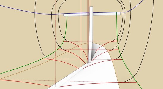
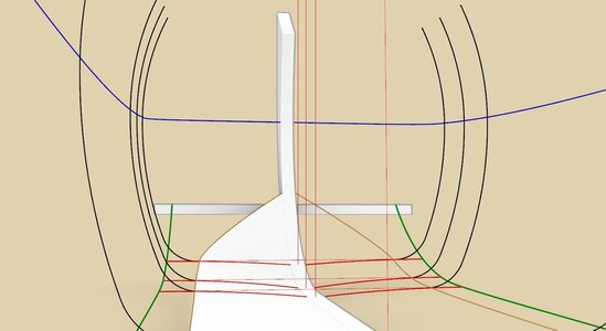
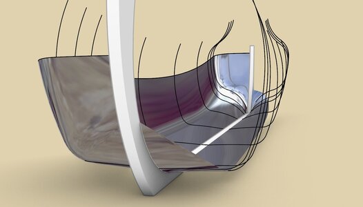
The same is shown in the 3D diagrams below. It just so happens that the 'flat' in Rålamb's fluit is concave throughout. This makes it possible for the transverse control strings/laths (thick red) to be placed anywhere along the length of the keel and at any density.

However, if the cross-section of the 'flat' changes, for example, from convex or straight (amidships) to concave at the stern, a larger gap should be left between the two sections so that the shape transformation could be smooth. The larger the gap, the smoother the transition of the shape.

The diagrams below are probably too clear to comment on in detail, but it may be added that the transverse control strings/laths (thick red) are perfect arcs of the circle, tangent to the straight sections (thin red) spanning between the hanging guide rails (green).


ViewCapture20230804_084125.jpg


ViewCapture20230804_084353.jpg


ViewCapture20230804_084311.jpg


ViewCapture20230804_084429.jpg

ViewCapture20230804_084535.jpg

.​
 
.​

Actually, the design concept of the Rålamb's fluit is too simple to continue. The radii of all futtock sweeps are the same (only they have different lengths), the radii of all bilge sweeps are the same (except the most extreme ones at the stern for its nice round shape). The translation of the printed text in Swedish, even in its ancient seventeenth-century specificity, is too simple. Boring, for me and probably for the readers as well.

I think I will now look around for some more challenging samples, though.

For now, thank you for your attention so far,
Waldemar Gurgul

.​
 
Back
Top