The boyer by Åke Rålamb 1691 – shaping Dutch hulls using graphic methods

.​

Ab, I am very sorry that you found the substance of my explanations disappointing. However, this way works in practice, and a substantive discussion with arguments of the "no because no" kind is simply not possible. Escher's drawings obviously have nothing to do here, and to contrast attractive form and correctness of the solution is not quite fair. Would this also mean that all your wonderful creations are worthless in terms of their historical reliability? Indeed, it would probably be best for you to present your own, alternative interpretation of this line, instead of suggesting the opposite and vague at the same time in an unspecific way that explains nothing.

Nonetheless, in accordance with your wish, I offer additional clarification below.

First of all, the method I have presented is very closely related to the essence of the bottom-first method, known from Witsen's descriptions, and actually follows directly from it.

Secondly, the contours of the frames obtained in this way agree very well with the contours of Rålamb's frames (you can check it yourself).

Thirdly, it is a mistaken assumption that the transverse strings/lattices would interfere with the work, as they did not have to be permanently mounted, but only applied for a moment to check the shapes obtained.

Fourthly, similarly, in the context of the possible obstruction by these longitudinal guides, one may associate them with scaffolding on the building construction sites. They, too, obstruct access to the façade to a certain extent, but are nevertheless always used.

Fifthly, the side guides outside the constructed hull I show, could in practice be both precisely set according to pre-calculated co-ordinates by the most rigorous shipwrights, but could equally well be set by eye by those less formalistic workers, giving almost equally good results. All that was really needed was for them to be more or less symmetrical, and their run in a generally correct manner, and even without much precision it was probably possible to build a somehow-floating hull. In this sense, it's a very practical, versatile method with the potential for widespread, convenient use.

Sixthly, what rule-of-thumbs are you talking about? I have just now demonstrated such a rule-of-thumb working in practice. Because it is not about the width of the flat at all, which is easily controlled by the obvious measuring, but its correct angle, variable along the length of the hull, which is much harder to control without this guide. The width of the flat and its inclination are two different things.

And one more general remark. The applied mathematical operations are so simple in this case, and the amount of resulting data (numbers) is so small that they could really be easily remembered or recalculated in the head on the spot, even without any abacuses or drawing these lines on paper. A person incapable of these simplest arithmetic calculations would also be completely helpless and incapable of independent living at all. Although I've heard that the Amazon Indians can only count to three, any number greater than that is "a lot."

.​
 
Let me start by saying that if anything I answered to your suggested solution of the riddle has offended you, I want to apologize. I thought we could discuss this in a friendly way with respect from both sides. If you see that differently, I deeply regret having mixed in your thread from the beginning. But I hardly believe it has to end this way. Let's just look at what we have here and try to explain what we see in the drawing without taking as an offence what was certainly not meant to be.

I have no solution for the question asked so I don't suggest any opposite and vague. I simply don't know where Ralamb gets his line from or what it stands for. When I saw you call it a' logarithmic curve' I was excited, because I thought you had found a way to construct or even calculate it. I was apparently wrong and sorry again, I don't see your explanation as very practical, apart from the fact that I never saw a painting or drawing where a construction like yours is pictured. Neither can I find anything in the written sources we have available, that sounds like such a method. In the full-size reconstructions and replica's I witnessed, I never heard of its desirability either.

But this hanging line is not the only remarkable thing in the Ralamb drawings. He shows us no less than 5 frames for his boyer, all drawn very accurately. How on earth did he do that? Does it have anything to do with the (provisionally rather misty) method he describes of which I placed the original drawing in post #9? I have the German translation of the text belonging to this method, if you are interested. The translator mentioned the defects, caused by misinterpretations and sloppiness of the engraver, so it will not really be an easy task to work this thing out, but it might give a clue to what we see here. There must be some geometry and mathematics in here, but that is much more your strong point than mine.

Let's not argue, but work together on this mystery.
 
.​

Thanks, Ab. I would be happy to undertake such cooperation or at least exchange of information and views, because conceptual issues are the most interesting for me. Although, I am a bit afraid, because recently there was even a brawl due to the heavy abuse of demagoguery by my debaters. And in such a seemingly safe issue as the technology from several centuries ago!

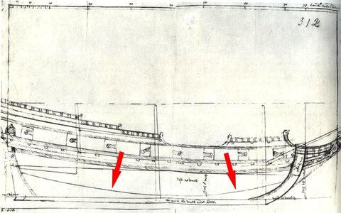
For now, I will only give an example of the line of the floor, or perhaps its variant in the form of a hanging guide line as interpreted by me and explained above, on the draught of the Dutch origin. This draught, or rather sketch, was made by Jakob Prunk – the Dutch professional shipwright in the Swedish service, around 1660.


Jakob Prunk 1660.jpg

.​
 
Last edited:
No harm done Waldemar, I consider it an honor to be working with you, even though it might me limited to exchanging ideas and other stuff.

The line in the drawing by Prunk (Pronk?) you show here is definitely the outline of the bottom, nothing geometrical. This is obviously an attempt to answer to a king's wish to present a draught before building the actual ship. As you can see, technically spoken this is not much more than an attempt, because in Holland a drawing was never demanded.
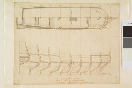
Another drawing (by Storck 1678) also shows a hanging line of which I am in limbo. What does it mean and how was it drawn?

a0149(0860) 30.3x39 kopie.jpg

This is one of the drawings of the Scheepvaartmuseum, Amsterdam I hold for being fake in some respect. I published several articles about them, but there are still some riddles to be solved. It is a proven fact that the drawings are 17th century. I hoped we could add the Ralamb drawings to the lot and draw some general conclusions.
 
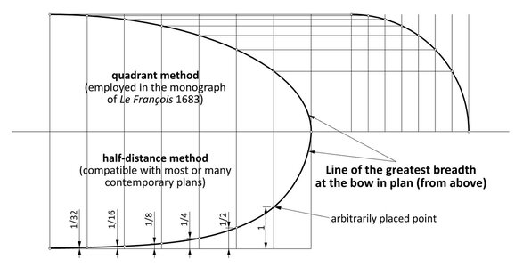
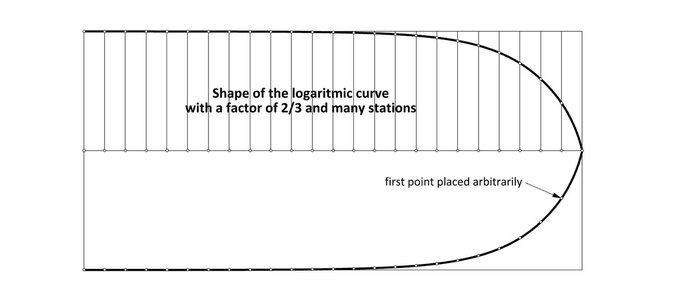
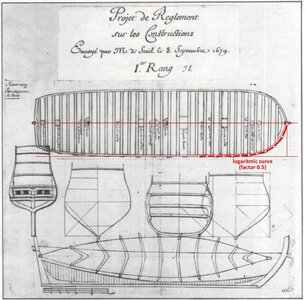
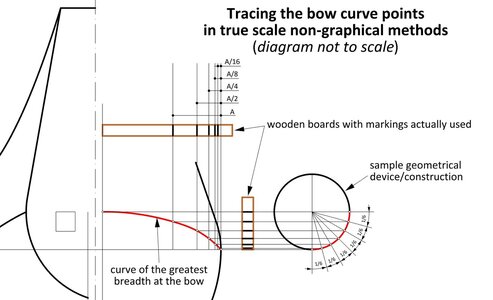
a logarithmic curve was drawn, starting from the last point (astern). All subsequent points were successively lowered (by half the height in this instance), up to the last one at the midship.

When I saw you call it a' logarithmic curve' I was excited, because I thought you had found a way to construct or even calculate it. I was apparently wrong and sorry again, I don't see your explanation as very practical


The function and the shape of a design line, although obviously related, are two different things and should not be equated. I have already given a recipe for constructing this line earlier in this thread, but presenting the whole mathematical theory behind trivial division by two would be overkill. Although I know that some people devote entire threads to explaining how to draw a line perpendicular to another line, for example. I'm assuming we've all finished primary school, so I personally find it a waste of time, both writing and reading.

.​
 
So, if I understand you well, Ralamb constructed this line. I do remember having finished primary school, but I must admit that I do not have ready the method to make a logarithmic curve, and I suppose many readers with me. So perhaps you could take the trouble explaining it to us.

Perhaps you can also elucidate why it starts high at the stern and ends somewhere in the middle of the stem. How and why were these locations chosen? It is obviously not the bottom in side view like in Pronk's drawing, because that would cause a massive problem with the planking of the aft part of the hull.

Is there any possibility that there is a connection to the English 'rising line of floor'? You have worked with these things into great depts, so if anyone can tell, it's you. Ralamb may have been a gentleman with clean sleeves on his shirt, but he must have had his eyes wide open, considering his ambitious encyclopedia project. We are not looking at nonsense here.
 
Does it have anything to do with the (provisionally rather misty) method he describes of which I placed the original drawing in post #9? I have the German translation of the text belonging to this method, if you are interested.

Ralamb's drawing, which you showed in post #9, is easily recognisable as depicting the simplest variant of the English hauling down/pulling up method. One don't even need to read the description of this drawing as all its usual components are clearly seen: the floor sweep, lower breadth sweep and the reconciling (futtock) sweep combining them.

.​
 
.

Perhaps you can also elucidate why it starts high at the stern and ends somewhere in the middle of the stem. How and why were these locations chosen? It is obviously not the bottom in side view like in Pronk's drawing, because that would cause a massive problem with the planking of the aft part of the hull.

The high position of these guides translates into sharp forms of the hull, the low position – into full hull shapes.

These hanging (guiding) rails are very near equivalent of the rising line of the floor, as they both perform exactly the same function, as shortly explained in the above cited excerpt. Geometrically, they may be constructed by almost any type of curve (be it straight line, ellipse, arc(s), logarithmic curve), depending on the designer's objective and skills. As a last resort, they can even be shaped/drawn manually, i.e. without any aid.

Could you elaborate on the supposed massive problem with the planking of the ship? I can't see any, assuming these lines are a sort of lines of the floor, and not some outlines of the bottom of unknown meaning...

.​
 
Last edited:
.​

Oh, Jules! Hello again! :)

Yes, that may be quite the right explanation for this particular line, which I will check in a few hours. In either way, I still find my method very possible and convenient to use anyway. Can you think of anything more practical than relying solely on the eye in this method?

.​
 
Last edited:
I like the M.C. Escher references. Model plans and instructions are often about as likely to lead you to a logical, real world solution as that!Cautious
Sounds like Waldemar is referring to what they call on the Easten Shore of the Chesapeake Bay the " Winchum Squinchum" method.
Eyeball and Thumbsup.
 
Last edited:
.​

Peter, this really isn't some interplanetary championship of demagoguery. You can say something of substantive value here. Please :)

.​
 
Last edited:
.​

Yes, on this point Jules correctly pointed out that this line is for the ship below on this plate (i.e. English hoy or schmack). But I also want to make it clear that the way I found by chance, allowing precise control of the angle, and even more importantly – curvature of the bottom „flat” of the hull is the only way known to me (and probably anyone) that gives at least correct reconstruction results, especially valuable for the most troublesome aft part of the hull, and consistent with the lines on the preserved plans and at the same time realistic. Unless someone is satisfied with the method that Peter calls "Winchum Squinchum", which has also certainly been used in the past.

.​
 
.​

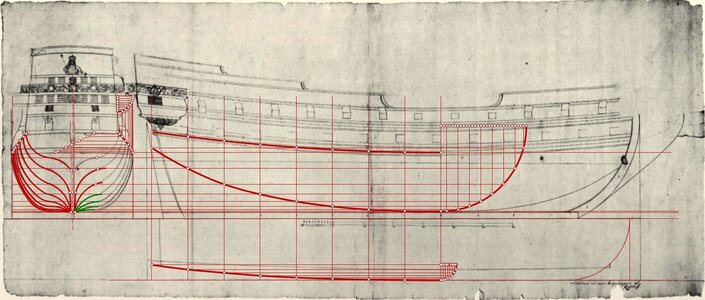
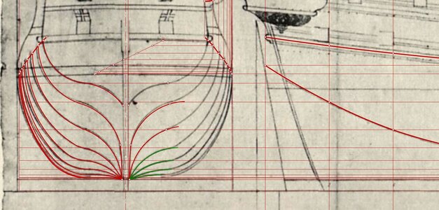
Perhaps to conclude already, one more plan from the Danish archives (A944), made in the mid-17th century. This time it is of a warship with sharper hull forms, so necessarily of a different geometric design. However, all the hull features are characteristically Dutch (except perhaps the decoration), including the distinctive frame construction , in which there are no separate futtock (reconciling) sweeps and lower breadth sweeps. Here they are a single circular arc of variable radius.

Significantly, most of the bottom arcs (in green) are tangent to lines coming from the floor line, exactly as in my proposal. Only the last ones, because of the peculiarity of the shape, are tangent directly to the futtock sweeps.


ViewCapture20230724_195752.jpg


ViewCapture20230724_195752 - Copy.jpg

.​
 
.​

On reflection... Yes, Ab is right, a bit more can and should be said about these extremely simple to use logarithmic curves. Also to show that they were known and applied by shipwrights of Dutch origin as well.

The graphics below are from my thread on another forum – Bow shape of Le François 1683 and La Néréïde 1722 (https://modelshipworld.com/topic/32948-bow-shape-of-le-françois-1683-and-la-néréïde-1722/).


Comparison of the elliptical curve (top) with the logarithmic curve (bottom), along with the method of how they are drawn:

ViewCapture20220912_092828.jpg


Example of a logarithmic curve for densely spaced stations:

ViewCapture20220917_110434.jpg


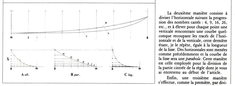
Examples of different curves given by Jean Boudriot. Among them, the logarithmic curve, denoted by the letter "C":

Boudriot.jpg


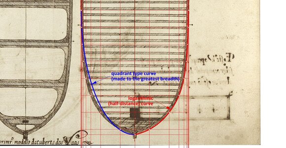
Example of the application of the logarithmic curve on a plan from 1616, by the Portuguese shipwright Manoel Fernandez in his Livro da Tracas de Carpintaria:

ViewCapture20220915_001733.jpg


An example of the application of the logarithmic curve by the shipwright of Dutch origin in the French service, Laurent Hubac, from 1679. Incidentally, this plan displays an unmistakably general Dutch design concept and structural features as well:

1679 - 1st rate ship of the line - project - 1.jpg


An example of the practical application of the logarithmic curve for tracing the contours of frames on a body plan or right away on a mould loft in the shipyard:

ViewCapture20220916_202213.jpg

.​
 
.
Interesting discussion here gentleman. Think we can learn a lot here and come to new insights. Hopefully this post will continue, seems the knowledge and input are present from multiple sides.


Maybe the guests will lead this thread a bit now? I'm a bit sarcastic because I just remembered one of the more extreme cases I had on another forum – it wasn't until a completely worthless and endless sermon by some commentator in my thread that caused a frenzy of enthusiasm among the audience. In fact, it was even funny. They mistook the ship's forum for a church service?

.​
 
.​

As can be seen from the contemporary graphic examples shown above in this thread, and also those presented in the thread on Chaillé's frigate of 1686, Dutch 17th century ship design could be geometric par excellence and expressed graphically on paper as well, had the authorities so required, under condition of course, that the draughts were not done by landscape painters, but by professional shipwrights with technical drawing courses provided. Given, for example, by land architects, which was certainly already practiced in France at that time.

I am also planning to perform a likewise reconstruction of the shapes of the fluyt from plate G in Rålamb's work, on a very similar principles as here, with just minor modifications, but that's probably in a separate thread.

.​
 
Last edited:
.​

Hello Jules,

Yes, this is, of course, a perfectly geometric construction, like in the Danish plan from 1665, Laurent and Étienne Hubac's designs for the French government, Ole Judichær's at the turn of the century or Åke Rålamb's quite accurate sketches.

It had to be used, if only because each conceptual method necessarily began with determining the shape of the main frame. And if not this way, then how? A rather rhetorical question. Also, for boxy hull shapes, such a "template" directly provided bilge and futtock radii for most of the ship's frame components (as I showed in this thread), which had to be specified when ordering at the supplier the needed timber.

The method of shaping this main frame was so simple, that in my opinion (which you may or may not share) there was no need to even draw it. After all, these are just a few numbers to remember or to simply recalculate in one's head if necessary. A drop in the ocean compared to „billions” of other numbers needed to build an entire ship – it is enough to look at a multitude of contracts, various types of cost statements, material needs, etc.

Cheers,
Waldemar
.​
 
Last edited:
.​

Personally, I interpret this particular statement by Witsen in a more extended, variant way:

„The figure at the letter W, at the top, shows how to make the construction on paper [if one so wishes], before starting on the Ship”.

Since I know that perhaps all languages as tools of communication have the potential to be quite unreliable when it comes to the precision of the expression of thoughts, and the writers themselves are not always disciplined in this respect either. I myself edit my texts sometimes many times over in order to finally express what I mean as precisely as possible. What I mean by all this, is that it would be rather imprudent to always take every statement strictly literally – for example, awareness that sometimes a quantifier may simply be missing (like "usually", "always", "sometimes", "rarely", etc.) is very important. I am sure you yourself have similar experiences.

As to the main frame morphology, these are my current general views:

Judging by various examples in more or less theoretical works of the period (e.g. Oliveira 1580, Lavanha 1610, Fernandez 1616, Furttenbach 1629, Fournier 1643, Witsen 1671, Dassié 1677, Rålamb 1691), this very simple shape of the main frame must have even been common and used all over Europe (only in the English hauling down method was a lower breadth sweep added). Therefore, one could probably speak of a fairly universal shape used throughout the continent. However, truly interesting things begin only in the next phase of building of ships, i.e. when transforming the shape of this "template" frame along the hull in the various conceptual methods (réduction de couples).

For this period, personally, I would most generally distinguish the Mediterranean method and its derivative English hauling down method, as well as the North Continental methods, even without narrowing them down to the Netherlands alone. For now I guess that the term "in the Dutch way" could for the contemporaries commonly mean the bottom-first method, which had already died out in other parts of the continent, at least for building larger ships. After all, medieval cogs built with this method were also made in the German Hanseatic cities in the north, not to mention even more ancient archaeological examples.

But let me tell you honestly that synthetics are very risky (yet unavoidable), this is why I prefer to focus on the analysis of specific cases.

,.​
 
Last edited:
Back
Top