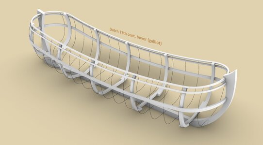
The boyer by Åke Rålamb 1691 – shaping Dutch hulls using graphic methods

Joined
Apr 26, 2023
Messages
383
Points
323

Location
European Union
.​

Despite the enormous scale of shipbuilding in the Netherlands in the 17th century, and the unparalleled, extraordinarily extensive Dutch works on shipbuilding of that period, the details of the conceptual shaping of hulls are not entirely clear, as evidenced by various disputes that are still going on today.

In this particular context, it should be emphasized that the intention here is not so much to enter into these disputes, and even more so to settle the practices applied at that time, but rather to verify whether it is possible to design a credible shape of a "typical" Dutch ship in a graphic way, using regular geometric methods, based on information coming directly from sources. Particularly useful data of conceptual nature can be found in materials of Danish and Swedish origin, where ships were also built using Dutch methods in this period.

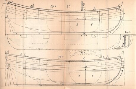
A good example for such an attempt is the plan of the Dutch boyer, with its accompanying description, in Skeps Byggerij 1691 by Åke Rålamb (upper vessel on the draught below).


Skeps Byggerij - TaflC-2.jpg

.​
 
Last edited:
.​

I too thank you for your interest, Ab. Actually, I've already finished the essential part of the work, and in the course of it I've come up with so many different detailed insights that I'm not sure I'll remember to write about all of them in the upcoming comments, especially given my efforts to be as concise as possible. In case of any such ambiguities, just ask, and chances are I'll be able to give a factual answer.

.​
 
Last edited:
.​

Even before explaining the details, I will say straight away that the application of a few simple rules has produced shapes that are near to perfection in a geometrical sense, requiring little, if any, adjustments. In fact, these rules are so simple that wasting time and paper writing them down or drawing plans could probably expose professional shipwrights to ridicule, at least for standard designs.

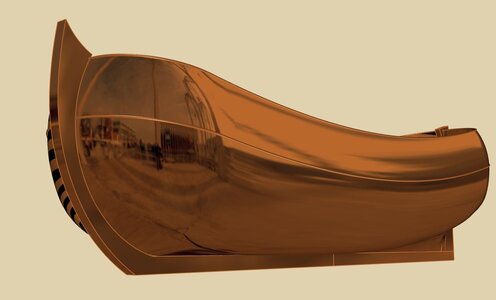
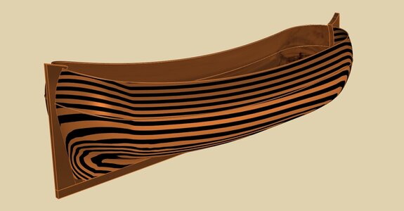
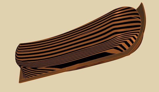
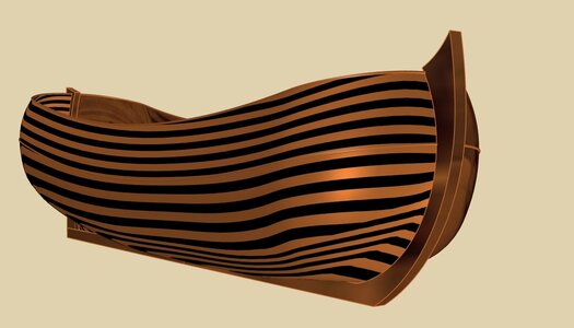
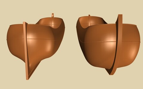
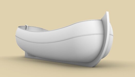
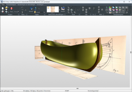
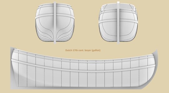
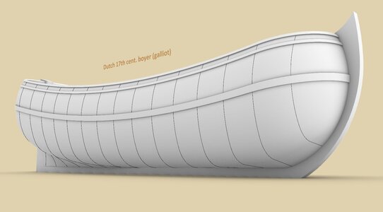
While preparing more detailed diagrams, for now a few renders with general views of the resulting shapes (no corrections whatsoever applied).


ViewCapture20230721_231249.jpg

ViewCapture20230721_231402.jpg

ViewCapture20230721_231438.jpg

ViewCapture20230721_231520.jpg

ViewCapture20230721_235355.jpg

ViewCapture20230722_005201.jpg

.​
 
Last edited:
Beautyfully rendered and very recognizable as a Dutch vessel. Thank you so much.

I have some doubts about the name of the type. In the 17th century the boyer was a very old fashioned type, which was gradually replaced by types as galliots and wide ships. If my information is correct (and there are always lots of reasons to doubt that) the top planking of a boyer ended in an open triangle just above the stern post, to give acces to the helm, entering the ship. I would call this ship a galliot, a so-called 'draai-over-boord' (litt: turn-over-board) referring to the helm, which has much more swing compared with a boyer. The way it shows now it might even be a (fish)hooker. But the size of the ship could be decisive. If I take the depth marks at stem and stern (resp.8 and 9 feet) the ship must have been closely to 65 feet of length (18.40 m depending of the used foot size), which is quite small for a freighter, but fits the size of a hooker.

If I interpret Ralamb's drawing correctly he offers two possible hull shapes for the same ship. One with an angled bilge and one without (or does the lower hull end up in a flat tuck?). I havent had his book in my hands for over 10 years (I had a copy in my workshop in the museum), but I would be very interested in what he has to say about this drawing. So far we 'only' have a shape.

The rigging for boyers usually consisted of what we call an 'anderhalve mast tuig' (litt: one and a half mast rig). That means a normal mast at about one third of the ship's length and a small mast in the back. One more reason to consider the ship to be a hooker, which had only one mast.

In how far geometrical shapes like circles and ellipses were involved in this design? Can you say anything about the construction of the main frame?
 
Last edited:
.​

Thanks a lot, Ab. For naming matters, I rely entirely on you because it's a devil that only a few can contend with :). Admittedly, I must stick to the name given by Rålamb (i.e. Hållensk Båyort), but to avoid possible misunderstandings I will try to use double nomenclature, i.e. "boyer/galliot" or similar.

The vessel is described by Rålamb more or less this way: It is a Boyer in Dutch manner/ commonly used here in Sweden/ built for sailing and somewhat for freight/ Of 65 feet length between posts and 16½ feet breadth/ Carries 60 ordinary lasts. And capable of carrying all types of cargo/ Should it be required to sail in shallower waters, the waterline must be laid lower, as its draft now is 9 foot/ In effect, it may then draw less, i.e. 8 foot.

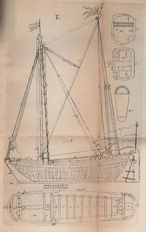
As for sharp bilges, Rålamb thus shows one of the boats, which he calls Dutch or Ship's Äsping, of 20 feet length and 6 feet breadth (plate B, fig. 6). Sharp bilges are also depicted on a vessel on plate E, which is described by Rålamb as „called Cagh (Kaag) in the Netherlands”. These sharp bilges can be clearly seen in the reproduction below:


Skeps Byggerij - Tafl.E.jpg


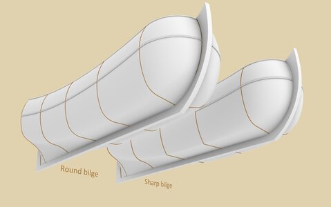
As if on my own initiative, I also made a second variant of Rålamb's boyer/galliot, sporting sharp bilges. If only to check this possibility in the case of vessels from earlier decades of the century or, for example, for later, smaller units. This is technically entirely feasible, and even in its extreme form with no bilge sweeps at all, as can be seen in the render below. Just two midship frames were accordingly replaced, the other three frames keep the same shape as in the variant given by Rålamb.


Round bilge - Sharp bilge.jpg

When it comes to design-geometric details, I will describe it all in the next posts, so that this post would not grow to the size of encyclopedia.

.​
 
Last edited:
Hej Waldemar and Ab,
Nice to see Waldemar taking this on, as I have wondered a little about this design in Rålamb. I think that the boyert (Swedish variant) survived as a type name a little longer here than in the Low Countries, and we did not adopt a variant of hooker. Eventually vessels in this size range with a two-masted rig (although a more substantial after mast) came to be called galeas in the 18th century, readily equivalent to the English galliot.

Boyerts were a common type of naval auxilliary craft from at least the early 17th century here, and were also used as harbour service vessels (lighters, etc). The navy yard in Stockholm usually had one or two in service.

Waldemar's digital work is, as always, lovely.

Fred
 
.​

At the outset, it should be emphasized that in this particular case, the economy was the top priority, both in terms of the cost of construction and the subsequent operation of the ship. Unlike specialized warships, which required the best possible sea properties, and whose hulls usually had more sophisticated shapes, here a boxy form was deliberately used with only the necessary modifications for tolerable movement in the water. Such a choice not only optimized the carrying capability, but also allowed the use of cheapest set of timbers of both uniform and little curvature for most of the hull. Also, the design concept itself is simplified to the absolute minimum, achievable in fact for shipwrights at almost any level of general education.

These perhaps may be generally known issues, only having been recalled here because they have a decisive impact on the specificity of this project, its analysis and interpretation.

Spine assembly and dimensions
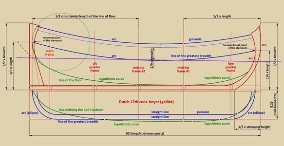
The dimensions in the diagram are taken from the text description and are in most cases (but not always) consistent with the original plan. Sometimes it is an obvious mistake in the text, and in other cases it may be the result of inadvertent drawing inaccuracies. Particularly noteworthy is the lack of the upper keel line, or in other words, only its lower edge and both rabbet lines were drawn on the side view.

Line of greatest breadth (blue colour)
In the top view of the original plan, both curves of this line, closing the hull at both ends, have been conventionally drawn as arcs of a circle, resulting in kinks at their junction with the straight side. This was corrected by replacing these arcs with elliptical curves.

Floor line (green colour)
For these lines, logarithmic curves give the best fit on both views. Contrary to appearances, logarithmic curves are probably the easiest curves to obtain, not requiring knowledge of their theory or even awareness of the existence of such a theory. Simply knowing how to divide, for example by two, is enough.

In the aft part of the hull, part of this line has been additionally modified as shown in the diagram to get even stronger sheer in this particular spot. In the top view, this line has a form that deserves to be discussed in a separate post, together with the issue of shaping the cross-sections of the hull.

The longitudinal position of the leading frames
As in van Yk's description, there are two main frames, two quarter frames and a stern frame (equivalent to fashion pieces on ships sporting square sterns). Both extreme frames are located as close as possible to their respective stems. The fore quarter frame is placed exactly at the junction of the straight line of the ship's side with the ellipse of the bow.

The limited number of leading frames is not accidental, being quite sufficient in this simple-shaped hull. On the other hand, a larger number of them would even be harmful, potentially causing surface irregularities. In contrast, in warships with more complex shapes, the number of these leading frames would have to be larger in proportion to the length of the vessel in order to correctly reproduce the desired shapes. When creating 3D models of hulls, all this comes out quite clearly.

ViewCapture20230722_184008.jpg

.​
 
Last edited:
Funny that you mention an Encyclopedia. Did you know that Ralamb wrote such a voluminous book? I share this internet fragment with you:

'Åke Rålamb (1651-1718), the son of Baron Claes Rålamb and Anna Stålarm, served in the Life Guard, becoming a colonel in 1711. He is the author of an encyclopedia, entitled 'Adelig Öfning' (Noble Exercise), of which six scattered volumes appeared in 1690–1694, on arithmetic, surveying, rapid writing, fortification, shipbuilding, economics, household, etc., with engraved copper engravings executed by the author. An extract, including interest calculation, became a chapbook under the title 'En liten handbok af adeligöfning' (a small handbook of nobility) and was published in a number of editions until the 19th century.
His 'Deduction how large land acquisitions came illegally from the crown' was published together with a writing by Edvard Ehrenstéen in 1709. He is also alleged to be the author of a handwritten writing 'Refuting the clergy' in Stockholm's sermon on tax money in 1693, which was subject to prohibition. In the Rålambska collection in the Royal Library there are several collections of royal letters and decrees on various subjects, prepared by him. A "Samblebook" of laws, constitutions and more prepared by Rålamb (19 volumes of folio and 7 volumes of "key") was purchased by the Swedish state in 1698 for 6,000 thalers of silver coins and is held in the National Archives.'

Part ten in his encyclopedia was about shipbuilding. It is hardly defendable that he has been a real expert in shipbuilding, amongst all these other specialisms. I seem to have read somewhere that he and Nicolaes Witsen met in Amsterdam (gentlemen among themselves...) That he was not a 'man of the trade' is not surprising for a nobleman like him. Like Witsen (and many more patricians) he seemed to have felt the publishing of a contribution to society as one of the tasks in a gentleman's life. That's why he probably wrote this work.

I recognize Witsen's instructions for the construction of the main frame in many of Ralamb's drawings. Tragic detail of his instructions is that they are totally useless. Nice for constructing a main frame, but for all the other frames we have no clue from where to draw our sweeps. But Ralamb offers the reader a method to construct some more frames:
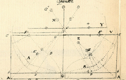
Schermafbeelding 2023-07-22 om 18.43.31.png
That is remarkable and this method should be investigated thoroughly, but that seems to be more complicated than expected.
I found the text referring to this page in my modest archive. It is a transcript/translation of Ralambs text for this page and the one before, written by a Werner Dammann in German. He complaints:

'Ralamb's work is almost 300 years old, written in an old-fashioned Swedish, which made the translation quite questionable in places. As Ralamb himself complains, the engraver made a few mistakes, and mistakes by the typesetters may have crept in - as far as the mistake was recognizable, I corrected it in the translation, but this was not always possible. Below are some expressions that may have different meanings or are unclear from case to case. Width: the expression is also used by Ralamb for length! half width: is used by Ralamb both for the body plan and for the top view, but can also refer to dimensions, which is often very confusing. Ridge is always the highest point of an arc or curve. Impact is always the circle - impact meant. Point can be the starting point for the point of the compass as well as a reference point provided with a code letter. Ralamb says in all Centrum, which is only partially correct. Letters - spelling: the spelling of Note - Letters differ between text and drawings in some cases. For example, the frames have letters that are not identical to those of the side and top views. In addition, upper and lower case letters were mixed up several times. Bottom width: the expression could not be clarified. [Ralamb, page 3, line l] Fractions in Ralamb: page 2 line G, 5th line, the denominator of the fraction cannot be identified [6/?].'

Many tests show that only seldom the constructed main frame as described by Witsen, matches with anyone described in specification contracts. I always had the feeling that Witsen added this peculiar method to compete with the book 'Hydrographie contenant la Théorie et la Pratique de toutes les parties de la navigation' (1643) by Father Fournier whom he admired much. A technical construction always looks much more interesting in a book than just some rules of thumb Witsen could refer to. Nevertheless Ralamb succeeded in presenting something, probably with more chance of success. In his 10th chapter he gathers a lot of interesting information.

Ralamb writes that, different from what I expected, the lower drawing presents another ship type than the upper one. The latter presents a boyer to be used as a freighter, the other one is an English 'Gay' (?) or Schmack for fishing and for transportation of general cargo. I think here he made another mistake. Different from what he says, the lower one on the drawing is obviously a freighter judged by the big main hatch and the upper one the fishing boat. To me it seems that the similarity is more than a coincidence.
But I will stop here, before you all think I am crazy and try to steal Waldemar's thread. No way!

While writing these lines Fred Hocker's contribution came in. Thank you Fred for your explanation of the ship types. (and can you please answer my question which I sent you on July 3?

Not only Fred came in, but Waldemar offered his latest contribution as well. I should gain some speed in reacting. Well... it's the age.
 
Last edited:
.​

@fred.hocker

Many thanks Fred for the terminology clarification. Nevertheless, it is perhaps better to keep these both quasi-aliases for the sake of universalism – hopefully, when it comes to the specificity of the hull shape, at least in the underwater part, the two types probably did not differ from each other.


@Ab Hoving

Done, I have replaced the diagram in the post above. There are now two lines, both of the greatest breadth and gunwale.

As far as identifying the two craft from plate C, I think the shape of the bow frame would be deciding. For the top vessel (boyer) this frame has a flat bottom, as one would expect from the Dutch bottom-first method, while on the vessel below (hoy/schmack) this frame is quite rounded. Accidentally, this has to do with a discovery or a new interpretation, which I will present in the next post. I believe that this building related detail has not been shown before.

.​
 
Last edited:
.​

@Ab Hoving

When it comes to the line of the floor aft – first, a logarithmic curve was drawn, starting from the last point (astern). All subsequent points were successively lowered (by half the height in this instance), up to the last one at the midship. Then a circle (green in colour) was added, tangent to this logarithmic curve and passing through the rearmost point on the stern post (incidentally, the same point that terminates the line of greatest breadth at the stern). Finally, the unnecessary parts of these lines were cut off.

.​
 
Last edited:
.​

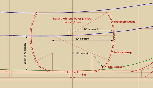
Even before describing the method of shaping the hull surface, below still a diagram of the midship frame, according to the proportions given by Rålamb for this vessel.

In any conceptual method, the shape of the midship frame had to be imagined before actual construction began, either in one's head or, in later times, on paper as a plan in graphic form. The particular shape chosen depended above all on the requirements for the designed vessel and, within practical limits, was not limited by the method used. For example, the stereotypical identification of Dutch conceptual methods with the small draft of ships is a nightmarish misunderstanding. In this sense, the Dutch methods were as flexible as any other, perfectly capable of creating ships of both small and deep draft.

The particular shape of the midship frame, shown below, can be seen as a compromise between the more rectangular shapes of highly specialised merchantmen and the round forms of warships, as Rålamb himself suggests when writing about the seaworthiness of this craft (Seglatie) and its ability to carry cargo (Last).

The flat of the midship frame has no deadrise (unlike in all other frames of this hull), and the bilge channel is formed by sloping the garboard strake, in typical Dutch fashion (shown in the diagram). An important peculiarity of the vessel is her uniform breadth along almost the entire length of the hull. This feature makes it in conceptually and economically very convenient way, that futtock and bilge sweeps for all the frames at this length can have the same radius as those in the midship frame (more on this in future posts).


boyer 1691 - midship frame.jpg

.​
 
Last edited:
Before you go on Waldemar, could you please elaborate about this logarithmic curve? What is it supposed to show? Where is it supposed to be in the body plan? It is even wider than the ship itself in topview!
I simply don't grasp the function and the general idea behind it.

My loyal cooperator Rene Hendrickx is working on the same drawing in Delftship now and gets (of course ) the same beautiful Dutch shape you have. I need this Delfship file to select the station lines I need in case of making a model. Then I can compare the hulls.
Schermafbeelding 2023-07-23 123810.png
 
.​

This mysterious logarithmic line seen in the top view, not seen anywhere else, must be closely related to the way this ship was built, i.e. the bottom-first method. Or, more precisely, it is difficult to find another explanation for it. Perhaps we owe it to Rålamb the gentleman (as opposed to Rålamb the professional, as Ab noted earlier), who possibly didn't realize in time that he should ignore or suppress this line for a general reader.

Anyway, my interpretation of this line is as follows and, it must be said, results in near-to-perfect shapes, at least in the geometric sense.

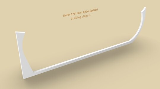
Stage 1.
Keel-posts assembly erected.
stage 1.jpg

Stage 2.
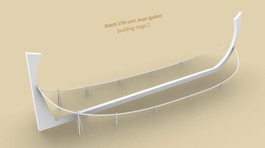
The guides of the bottom flat are mounted along the boat under construction. The coordinates of these guides are exactly the same as those drawn on Rålamb's draught. They terminate at both posts, however, in between these guides must clear the hull, i.e. be laid wider than the hull under construction, otherwise they would foul the work. The high position of these guides translates into sharp forms of the hull, the low position – into full hull shapes.
stage 2.jpg

Stage 3.
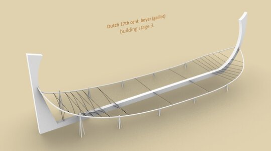
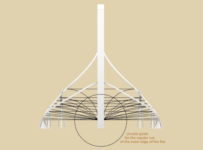
Stretching the transverse strings or lats, which could be done anywhere along the keel. In the central and fore part, i.e. where the bottom was intended to be completely flat, the strings were attached to the keel. In the aft part, where the bottom had to be concave, the strings connected both guides, and then the guiding lateral arcs were arranged. In this particular case, the best results were obtained by using circular arcs tangential to the transverse horizontal strings, passing through points on the both side guides and on the keel itself. I believe that it was possible to achieve the same effect in real practice without much difficulty.
stage 3.jpg

Stage 4.
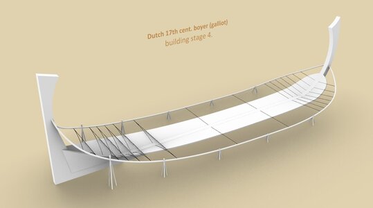
Planking the flat of the bottom. As can be seen, the run of these strakes and the final shape of the flat was, or at least could be, precisely controlled by transverse strings or slats explained above.
stage 4.jpg

In the next diagram, a way to get an even width of the "flat" is given. Only at the stern was the point of contact raised a few inches.
edge of the flat.jpg

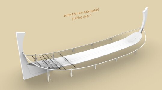
Stage 5.
Removal of a part of the strings with a rectilinear shape to avoid collisions with the bilge boards tilted upwards, which will be laid in the next stage.
stage 5.jpg

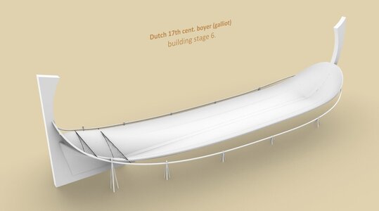
Stage 6.
About half of the bilge strakes have been laid. The strings might still be helpful at the aft end, but templates had to be used in all other places to be sure of the uniform roundness of the bilge shape. In fact, just one template, with a radius equal to the radius of the bilge sweep taken from the midship frame.
stage 6.jpg

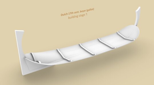
Stage 7.
Insertion of floors. The ends of these timbers have, again, a radius equal to the radius of the bilge sweep taken from the midship frame.
stage 7.jpg

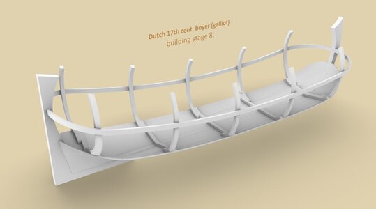
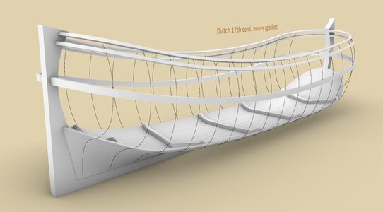
Stage 8.
More or less simultaneous erection of a wale (or actually its temporary equivalent) and of some leading frames. All these timbers have the same two radii, taken from the midship frame, i.e. bilge and futtock sweeps. Only the last, aft rib has a bilge sweep radius that is one and a half as large to obtain a nice, round shape of the stern, which, incidentally, agrees with the contour of this frame as drawn by Rålamb.
stage 8.jpg

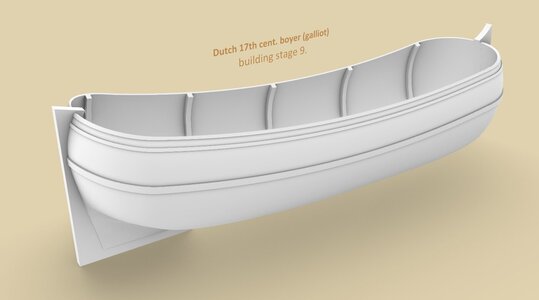
Stage 9.
Enjoy. :)
stage 9.jpg


As can be seen from the above, the entire procedure of the bottom-first method can be expressed in perfect, and more importantly, historically correct geometry, despite the fact that plans in graphic form were not used at all for the construction of real sized ships.

.​
 
Last edited:
Thank you very much Waldemar, how beautifully explained and illustrated.

The trouble with beauty has always been that it can be incredibly misleading. Of course you know Escher's work in which he clearly shows water running upwards and stairs climbed sideways. You are aware that your leg is pulled, but you cannot say what is wrong in the beautiful images he presents.
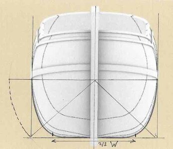
What I mean to say is that if the mysterious hanging line in Ralamb's side views was meant the way you draw, it can impossibly have been wider than the ships total beam. If a shipbuilder thought he needed to help his experienced eyes with a batten that showed the run of the bottom of his ship (for which he had perfect rules-of-thumb anyway like: width bottom = 2/3 of width ship), why would he not place it where the outside of the bottom really was supposed to be? Why so much wider on a place where it in all probability would be hopelessly in the way during work?

I hoped you had come with a geometrical solution for this 'logarithmic curve', like the 'sent-lines' the Dutch shipbuilder Van Zwijndregt shows in his manuscript from 1755. He draws a square in which the frames are constructed, using diagonal lines from stem and stern to the far low corner as an aid. Once pivoted in a flat such diagonal lines might very well stick out from the circumference of the ship. (sorry for abusing your drawing)

sent-line.jpg

The question is: how did he construct it. Preliminary designs on paper? And the second is: does this show daily practice on shipyards of his days or is it just an intellectual addon configured by an ambitious gentleman?
What is truth here?

It is my firm conviction that constructing shapes of frames prior to the actual build only works with the adoption of mathematics in the whole concept. Longitudinal lines that can be explained geometrically, like you showed so unsurpassed in your reconstructions of English design methods. But so far I havent seen them in the scarce Dutch drawings we have.

To round it up, I don't think we have the final answer for this mysterious hanging line yet.
But I am very interested in any other explanation, because I simply don't grasp it.
 
Last edited:
Back
Top