
Thanks Splinter. My Spanish isn’t good enough to get all he’s saying but the videos are still informative.I came across this on YouTube, it might be fun to watch, there are now 101 episodes

Le Rochefort de ANCRE: Introducción al Modelismo de Arsenal Ep. 1
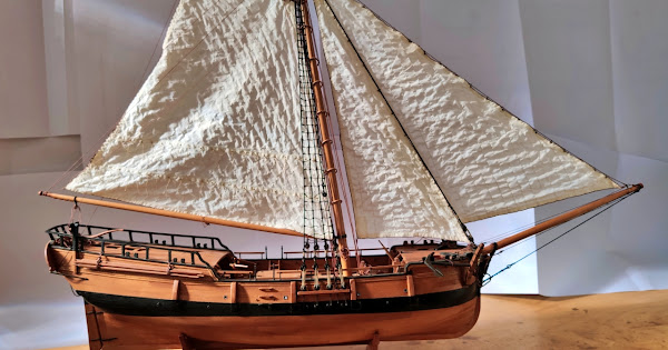
Le Rochefort es un pequeño yacht de construcción simple que se usaba en el puerto-arsenal de Rochefort para asistir y equipar los barcos anclados en la rada ...www.youtube.com

You are using an out of date browser. It may not display this or other websites correctly.
You should upgrade or use an alternative browser.
You should upgrade or use an alternative browser.
"Start-up Conversations" and "Build Support-Tips, Advice" here.

One tip:Thanks Splinter. My Spanish isn’t good enough to get all he’s saying but the videos are still informative.
activate the "subtitles" and in "Settings" you can activate the automatic translation into english or any other language
This may help
")
BTW: a good find

Uwek, thank you for this tip on translation activation.One tip:
activate the "subtitles" and in "Settings" you can activate the automatic translation into english or any other language
This may help
BTW: a good find
As there were many discussions about the thickness of the keel and keelson I would like to summarize my findings about this.
I guess this thread for tips is the right place to post it.
Thanks also to Tobias who was the perfect sparring partner for some discussions and to make me think about it.
All dimensions below are valid for 1/36 scale.
As a result I consider the 6.95 mm shown in Adrian's book as wrong, 6.75 mm as final thickness (width) of the keel would be correct.
Starting point is the chapter "Scantlings of the wooden framing" at the end of the monograph:

Please note also, that the keelson has at the stern a separate part (rear keelson in below image), marked as "k" on plan 2. This part of the keelson is less wide (6.75 mm) compared to the rest of the keelson (7.5 mm). I came to the 6.75 mm for this part by comparing it with the width of the keel. Both parts are showing the same width in my point of view. I checked it with caliper and magnifying glasses.
Note: The same is valid for part "j" at the front.
So both ends of the keelson (k and j) are only 6.75 mm wide and not 7.5 as the rest of the keelson.

Here are some measurements/dimensions of the single parts:


That this rear and front part of the keelson is less wide can also be seen on different parts of different plans. Only shown for the rear part in the following images.


So in a nutshell:
Width keel: 6.75 mm
Width keelson: 7.50 mm
Width rear and front part of the keelson: 6.75 mm
I hope this helps and was not too confusing.
I guess this thread for tips is the right place to post it.
Thanks also to Tobias who was the perfect sparring partner for some discussions and to make me think about it.
All dimensions below are valid for 1/36 scale.
As a result I consider the 6.95 mm shown in Adrian's book as wrong, 6.75 mm as final thickness (width) of the keel would be correct.
Starting point is the chapter "Scantlings of the wooden framing" at the end of the monograph:
Please note also, that the keelson has at the stern a separate part (rear keelson in below image), marked as "k" on plan 2. This part of the keelson is less wide (6.75 mm) compared to the rest of the keelson (7.5 mm). I came to the 6.75 mm for this part by comparing it with the width of the keel. Both parts are showing the same width in my point of view. I checked it with caliper and magnifying glasses.
Note: The same is valid for part "j" at the front.
So both ends of the keelson (k and j) are only 6.75 mm wide and not 7.5 as the rest of the keelson.
Here are some measurements/dimensions of the single parts:
That this rear and front part of the keelson is less wide can also be seen on different parts of different plans. Only shown for the rear part in the following images.
So in a nutshell:
Width keel: 6.75 mm
Width keelson: 7.50 mm
Width rear and front part of the keelson: 6.75 mm
I hope this helps and was not too confusing.
Last edited:
Adrian's book <An introduction to PLANKED ON FRAME SCALE MODEL SHIP BUILDING "DOCKYARD STYLE> from ancre.fr is from my point of view a must if you want to build a model of the Le Rochefort. At least if you are a beginner like me .
But there is another source that is a good complement to Adrian's book:
This is a link to Adrian's Google Share Drive, which contains most of the images from his book. It also includes pictures of the rigging that is not in his book. For me, it's also very helpful to zoom in on some of the pictures to see some of the details better.

.But there is another source that is a good complement to Adrian's book:
This is a link to Adrian's Google Share Drive, which contains most of the images from his book. It also includes pictures of the rigging that is not in his book. For me, it's also very helpful to zoom in on some of the pictures to see some of the details better.

Dieter, thanks for that link, very useful.
Thanks for finding this Dieter! Excellent additional resource.
I asked GD about the tar which was used. His answer:
"The tar used is of vegetable origin, so it is reddish-brown in color. It is not mineral tar which is black."
Maybe this is an useful information for this group build and also for other models from this era.
"The tar used is of vegetable origin, so it is reddish-brown in color. It is not mineral tar which is black."
Maybe this is an useful information for this group build and also for other models from this era.
There was a very good finding from @Tobias, that there is a mismatch for the mast step on plan 6

Gerard's answer:
Bonjour,
Il y a en effet un petit décalage (1,25 mm au 1/36) que je n'explique pas sur la planche 6, il faut prendre l'implantation qui figure sur la planche 10.
Il faut que les varangues sèches de la carlingue soient centrées sur les varangues de la charpente.
Which translates (IMHO) to:
Hello,
There is indeed a small offset (1.25 mm at 1/36) that I cannot explain on plate 6, you have to take the layout that appears on plate 10.
It is necessary that the floor timbers (of the mast step) on the keelson are centered on the floor timbers of the frames.
In making the transom timbers I found an inconsistency between Adrian’s book and the monograph.
Adrian’s book says that the transom pieces are the same thickness as the frames (5.3mm).

However the plans measure 4.5mm

The 4.5mm thickness is confirmed in the Scantlings Chart in GD’s booklet.

I am discovering that we must pay close attention to the plans and GD’s booklet as those are the true “bible” for this build.
EDIT: The fashion pieces (number 9-G on plate 5) do start out as 5.3mm thick…
Adrian’s book says that the transom pieces are the same thickness as the frames (5.3mm).
However the plans measure 4.5mm
The 4.5mm thickness is confirmed in the Scantlings Chart in GD’s booklet.
I am discovering that we must pay close attention to the plans and GD’s booklet as those are the true “bible” for this build.
EDIT: The fashion pieces (number 9-G on plate 5) do start out as 5.3mm thick…
Last edited:
Question , I’m wondering if the frames are built up from various pieces . I’ve attached a photo from Dave Stevens thread of the Oneida which I
referred to for my Oneida build. To this point the
Oneida the Caustic and my current build the Halifax use this type of construction. Though they all are laser cut frames I have on many occasions remade parts to frames and completes redo of all frame members. This model may be a good choice for a build.
Your thoughts please
Thank you
Hello Mavrick, the frames consist of individual parts. It is a double frame. We would be delighted if you would like to join us.


Hello everyone,
I would like to point out a small error in the plans. The dimensions are wrong!!!


I would like to point out a small error in the plans. The dimensions are wrong!!!
The question will be, what is the correct dimension? I guess the deck drawing where the planking is shownHello everyone,
I would like to point out a small error in the plans. The dimensions are wrong!!!
View attachment 442087
View attachment 442088
View attachment 442089
I guess it is possible to see at the detailed drawing of the bitts ....
Hello Uwe, it's good that you mentioned it, it was my mistake not to have gone into it in more detail. Your assumption is correct, the drawing below is the correct one and it also matches the drawing of the detailed plan.The question will be, what is the correct dimension? I guess the deck drawing where the planking is shown
I guess it is possible to see at the detailed drawing of the bitts ....
