Pinas 1671 by Nicolaes Witsen – the backbone of the fleets

.​
:) It's quite a plan – to publish in a poorly circulated periodical with a forgotten title, and therefore probably rather unknown content...

* * *​

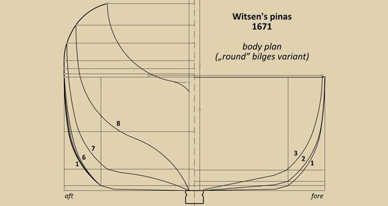
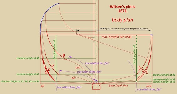
Body plan. The body plan has been drawn in exactly the same way as described in both my threads on fluits, i.e. futtock sweeps for almost all frames (except for frame #3) are of the same radius, and bilge sweeps for all frames are of the same radius as well. The bilge sweeps (thicker red lines) connect futtock sweeps (tangentially) and the „flat”, terminating at its edge (not tangentially). The only real novelty for the readers may be that the actual width of the 'flat' was determined not in a straight line in the case of its curved cross-sections, but along this curved line, which is shown in the diagram.

The coordinates given by Witsen are marked as small circles. As mentioned earlier, they are intended for shipyard workers and mark the boundary of groups of planks laid in successive, separate stages of the ship's construction. It would be difficult to demand an even better correspondence between these co-ordinates and the reconstructed hull lines, so consequently the design method presented.


ViewCapture20230831_154641.jpg

.​
 
Last edited:
These two are the best I can think of in our tiny, closed-circuit, world of ship and model enthusiasts. Perhaps Smithsonian magazine or the like in the E.U. or in England. Perhaps with one of the appropriate publications of the Dutch or Greenwich maritime museums and the like. I am sure that they would like all of your exhaustive efforts to see as much of the light of day as possible.
I think of my own many decades of creative efforts that are most likely destined for the dust bin of history after my demise. Such is entropy, the way of the universe. :rolleyes:

Pete
 
Last edited:
.​

Anyway, not a very popular theme this pinas, time to close the thread. Here are still the effects of rounding bilges in all frames in the way described in Witsen's work and also above in this thread, should anyone prefer this variant.

Thank you for your participation and attention,
Waldemar Gurgul


ViewCapture20230831_193237.jpg

.​
 
Waldemar! Now that I'm just catching on, you close the thread? Just when I'm starting to stretch my horizon, reach for a higher bar?
Well, I plan to go back, review the thread, and try to deepen of my understanding. Jeepers! This may not have been a topic that I initially had interest in, but now, thanks to you, I have a much better appreciation of this history and the naval architecture involved, as well as a whole new field of interest. It wasn't exactly a 101 class, but I'm all the better for sitting in. I hope that you will continue to share your knowledge, protocols for investigation and exacting standards (let alone your intellectual curiosity) with us on the forum! Thumbsup
I hope that you will soon entertain another topic of investigation.

By the way, I have become as appreciative of "virtual" modelling now as I have been of actual physical modelling due to your enlightening use of it.Okay

A new and devoted fan of your work, Pete:D
 
Last edited:
.​

Anyway, not a very popular theme this pinas, time to close the thread. Here are still the effects of rounding bilges in all frames in the way described in Witsen's work and also above in this thread, should anyone prefer this variant.

Thank you for your participation and attention,
Waldemar Gurgul


View attachment 392295

.​
Hi Waldemar,

I think you are wrong that this is not a popular topic. I saw it was the second or third best viewed topic of last week on the whole site.
It means a lot of people are looking and reading but are not giving comments. So people are definately interested in this.
 
Hi Waldemar,

I think you are wrong that this is not a popular topic. I saw it was the second or third best viewed topic of last week on the whole site.
It means a lot of people are looking and reading but are not giving comments. So people are definately interested in this.
Regardless of the number of people viewing this topic, this topic is still very interesting, especially so since the historical sources (the few there are) are confusing at best. For a number of reasons I started to read (part of) the publications of Witsen and van Yk, plus some analysis of Witsen's work and I can't say it helped me much so far. Especially when you're interested in the concept design of the ships of that particular era, there's preciously little background information.
 
.​

Thank you gentlemen for your entries. Admittedly, I still have a few interesting (at least to me) 17th century cases, but this whole „design concept campaign” has perhaps tired me out a bit and some rest is needed.

Waiting in the queue, for example, are the Swedish/Dutch Vasa 1628, the Swedish/Dutch Amarant/Spees 1653, the Danish Prins Carl/Prins Wilhelm 1696 and Ole Judichær designs of the same period, the Dutch VOC standard designs 1697, or the Danish/Dutch Stormarn 1703.

.​
 
.​

Thank you gentlemen for your entries. Admittedly, I still have a few interesting (at least to me) 17th century cases, but this whole „design concept campaign” has perhaps tired me out a bit and some rest is needed.

Waiting in the queue, for example, are the Swedish/Dutch Vasa 1628, the Swedish/Dutch Amarant/Spees 1653, the Danish Prins Carl/Prins Wilhelm 1696 and Ole Judichær designs of the same period, the Dutch VOC standard designs 1697, or the Danish/Dutch Stormarn 1703.

.​
You're welcome!

Since I'm neither a scholar nor a scientist, it takes me forever to search for and find relevant documents, yet I am interested in the big question "why", especially in all things related to the concepts of designs and lately in the designs of 17th century vessels. Having read some of both Witsen's and van Yk's work I am still left with the idea that we know to some extent how the ship's were build, but the why question is still unanswered for the main part. One of the issues which is also beyond me is the fact that no drawings or detailed specifications appear to exist for these Dutch ships.
These are a couple of reasons I was so intrigued by this thread; I was hoping for an exchange of information, ideas and possible scenarios.
Hopefully you'll find some energy again soon to continue this thread.

Kind regards,

Johan
 
.​
One of the issues which is also beyond me is the fact that no drawings or detailed specifications appear to exist for these Dutch ships.

Ah, the issue of the use or non-use of scale construction plans comes up again and again, but in essence it is only an apparent problem if one considers the methods of ship construction.

The point is that none of the methods of the time (whether Mediterranean, English or bottom-first) required complete plans on paper, i.e. including frame contours (except master frame), and in many or even most cases did not require them at all, especially for routine, conceptually simple designs.

Fortunately for us, in a few cases such (more or less partial) plans were nevertheless produced, as this gives us a better idea of how the rest of the ships were built.

Now, the issue of resolving the question of the use of plans, though for me rather rhetorical in nature. If, say, 99.5% of the ships were built without plans, and only 0.5% with the help of plans, what will be the correct diagnosis of this phenomenon if today 'everyone' necessarily demands only a clear 'yes' or 'no' answer?

Not using plans in graphic form does not at all mean that ships were built haphazardly, quite the contrary. For ships built in the Netherlands (and elsewhere), numerical written data were typically used, and any more detailed legal contract includes all or at least most of the necessary data to build the ship's hull according to the design intentions.

.​
 
Last edited:
.​

One might also add that, in this context, Ab Hoving's general approach seems – statistically – even more realistic. On the one hand, many selected parts of the hull structure had to be made precisely, yet, on the other hand, some could be made more freely. Let's take, for example, the shape of the line of greatest breadth at the bow. On a formalistic scale drawing, it might be represented by a precisely drawn ellipse, a logarithmic curve, an arc of a circle, or just a not-so-regular curve of similar shape. However, in reality, when bending the planks, eventually a 'not-so-regular curve of similar shape' will still come out.

And yet, making scale plans became more and more of a necessity. For administrative reasons, for the increasing division of labour, educational reasons, etc. The introduction of diagonals and waterlines of both a design and corrective nature finally put an end to non-graphic and partly-graphic methods (in the last decades of the 17th century, invented possibly somewhere in the Mediterranean). And this is probably how the eras in naval architecture should be distinguished – not by rather meaningless centuries, but precisely by the criterions such as the use or otherwise of diagonals (not to be confused with ribbands).

.​
 
Thank you so much for your replies, Waldemar. It's appreciated.
I can see your point on the necessity to have (or not to have) full sets of drawings. For what it's worth, your remarks threw me back in time, just when I started my career in design.
While not comparable with the different eras of shipbuilding, the engineering definitions of parts and assemblies were more or less complete, but not usable for production to manufacture and inspect the parts; a translation was required.
This translation could have various appearances, like sketches or full scale templates, press- and form blocks, jigs, tables for parts being very similar, but also master tooling etc, etc. In those cases, the engineering definition was no longer the "single source of truth", but the mentioned derivatives of the engineering drawings.
This shifted in the last fifty/sixty years or so, possibly finding it's roots in the mass production of WWII equipment and weaponry, which was needed in great numbers, thus requiring unambiguous definitions.
Also the authorities, involved in allowing cars, ships or aircraft to be used either by the general public or the military, required more accurate ánd traceable definitions. That led to the adagium that every engineering definition should be unambiguous ánd should be a "single source of truth". This probably found root in the minds of countless people around the globe and now we look back to times were different sets of rules applied, where no or limited drawing or sketches existed and where craftmanship played a key element in the final results, which is the diametrically opposite of today's industry position.
Essentially we should not impose our current day and age views on the shipwrights of the past: we are products of an evolution/development of four centuries or more.
Having said that, reverse engineering of ships of the past becomes more an more difficult and less accurate the further back in time one travels. Are we able to recreate ships from the past? Yes, definitely. With a high of accuracy? Probably not. My personal view on models of those particular eras is that they show us at best optimum how those ships could have looked.
Luckily there are still people around who are willing to put in time and effort to educate those willing to listen and learn.

Kind regards,

Johan
 
RDN1954,
So beautifully and succinctly put. This is a problem I encountered on a regular basis restoring period antique furniture time after time. Where the " expert opinion" was always cast in stone but the actual objects under consideration were most often full of anomalies. The farther back the in time the individual pieces went, the more the anomalies accumulated.
I am a fan of Baltimore Clippers of the War of 1812 period. No original drawings or plans exist (so far as is currently known). The only accurate lines were taken off by the British from captured examples. It is known, generally speaking, how they were built, and the conventions employed. But these were unconventional craft with rapidly changing and evolving purposes.
 
.​
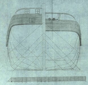
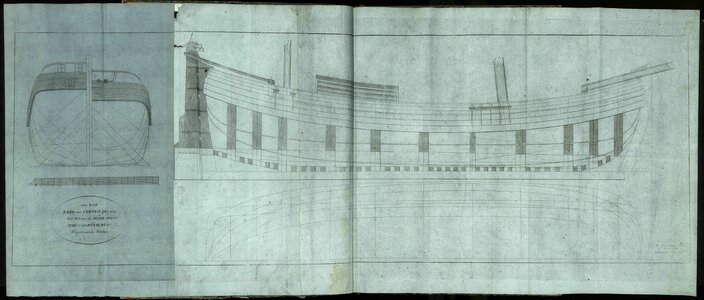
Thanks to the vigilance and kindness of Martes, I recently had the opportunity to consult a sensational, bilingual (in Russian and Dutch) album published in 1815 in St Petersburg – Drawings of merchant ships used in Holland for navigation on the Zuider Zee. The album contains plans and descriptions of ships of various types and sizes, and the hulls are already defined in a manner appropriate to the era, i.e. on the basis of diagonals, but one of the designs still features the construction detail, rather old-fashioned at the time of the album's publishing date, yet seemingly characteristic of Witsen's era – the rounding of the bilge in the carpentry manner, by means of an appropriate slant of the strake connecting the 'flat' to the 'vertical' sides of the ship.

Despite the rather large time gap, this specific detail seen on the attached plan illustrates very nicely in a graphic way the comments found in Dutch 17th century works on shipbuilding, which justify the inclusion of these reproductions in this thread.


Kof - Lang over Steven 76' 6'' Rhijnlandsche Voeten - Sections.jpg


Kof - Lang over Steven 76' 6'' Rhijnlandsche Voeten (1400x597).jpg

.​
 
Last edited:
Back
Top