Pinas 1671 by Nicolaes Witsen – the backbone of the fleets

Joined
Apr 26, 2023
Messages
383
Points
323

Location
European Union
.​

This is only the beginning of the work on Witsen's pinas, but somehow I feel that in this particular case the statement of Peter I, who, after learning shipbuilding in the Netherlands and later in England for months, would be appropriate: 'If I had contented myself with learning the art of shipbuilding in Holland, I would only have become a ship carpenter [and not a ship designer].' However, perversely, this was apparently not because Dutch shipwrights, at least some of them, were incapable of designing ships in an engineering way, but rather because they simply did not see fit to share this knowledge with the Russian ruler.

In quite the same way, as it now appears, they did not see fit to enlighten Witsen on the matter either, and if he was paying for the information, it is fair to say that he was cheated, so to speak. He was told almost 'everything': general hull shape requirements for different types of vessels, more or less simplified construction procedures, most typical proportions of ship dimensions and structural elements, etc., he was even allowed to measure ships and their parts in the shipyard (all also invaluable information today), but the most important thing – how to design ships in a conceptual sense – was denied to him.

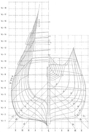
For, unlike common ships like boxy fluits and the like, with their extremely simple design concept, the pinas Witsen describes begins to appear as a rather sophisticated design for its era, already requiring a plan on paper beforehand.


General view of the pinas in Witsen's monumental work Aeloude en hedendaegsche scheeps-bouw en bestier, 1671:
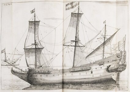
Pinas 1671.jpg


Witsen has included in his work the detailed dimensions of the various parts of the pinas and the co-ordinates of the distinctive hull lines appearing at the various stages of her construction as well, which makes it possible to attempt to reconstruct the shape of this ship, but even more interestingly, perhaps it will also make it possible to reconstruct her design concept. The necessary data can be found not only in Witsen's work itself, but also in the excellent book Nicolaes Witsen and Shipbuilding in the Dutch Golden Age by Ab Hoving.

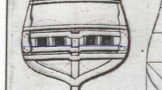
The reconstructed main proportions of the ship and the run of the line of greatest breadth (scheergang, scheerstrook), in blue, are shown below. The points on this line visible in the diagram are its coordinates measured by Witsen himself or his assistant. In the side view this line has the shape of an arc of a circle, and in the top view it is a logarithmic curve for both ends of the hull.
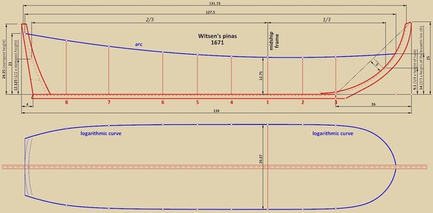

ViewCapture20230825_094458.jpg


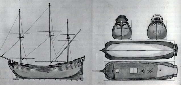
As a kind of a parallel, logarithmic curves were also used to form the line of greatest breadth by shipwrights of Dutch origin in the French service, Laurent and Étienne Hubac, in their chronologically not-too-distant designs of 1679:
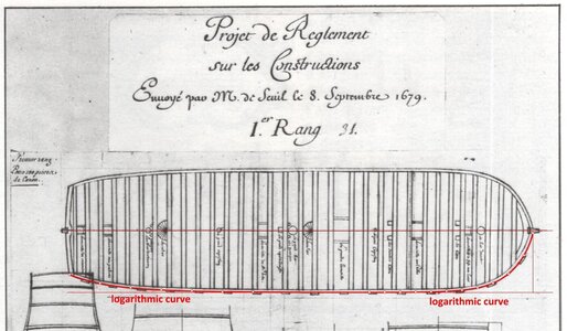
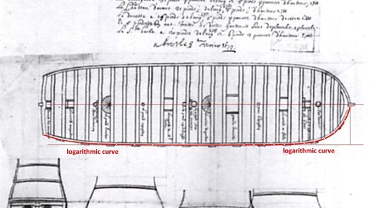
1er Rang - 1679.jpg


4eme Rang - 1679.jpg


Dimensions of the pinas' hull:

Length between posts: .................................... 134 feet
Length between rabbets: ................................ 131.73 feet
Horizontal length of the line
of greatest breadth: .......................................... 127.5 feet
Breadth: .................................................................... 29 feet 3 inches (length between rabbets / 4.5)
Depth (height of design grid
from keel to the line of greatest
breadth at midship frame): .............................. 12.75 (1/10 x horizontal length of the line of greatest breadth)
Longitudinal position of the frame #1
(most likely the midship frame): ....................... 1/3 of the horizontal length of the line of the floor.

The remaining dimensions are included in the diagram (note: this is a work-in-progress, so some details may change, which will be indicated).

.​
 
Last edited:
Hello,
I look forward to your contributions as I am also very interested in Dutch shipbuilding at the time. I already have one comment and one question.

1. It seems illogical to me if the line of greatest width in side view does not end at steven top. (If you look at the line cracks of the vasa, you can see that their greatest width leads to the top.)

2. How did you get the information that the top view line is a logarithmic curve?

Bela
 
.​

Hi Bela,

1. if you look more closely at the stern of Vasa 1628, and indeed many other ships of the era (plans or other iconography), you will notice that the wing transom is noticeably above the widest point of the stern surface. In other words, the wing transom, which is usually placed at the height of the sternpost top, is not necessarily the widest part of the stern (please take a look at the museum draught below). This is quite a normal circumstance in this era.

2 This is precisely one of the most challenging skills and difficult tricks that other researchers essentially do not undertake. In the simplest terms, by fitting and testing different possibilities, and not just for single curves, which would be much simpler, but in complex combinations with other curves, which must ultimately give a coherent, three-dimensional geometric structure, closely fitting to the available, source data.


Vasa stern - museum drawing.jpg

.​
 
Last edited:
Thank you for the execution. I wasn't specific enough in my first post. I meant the stem. The width decreases more and more towards the bow and is then almost at "0" at the stem. But this "zero point" can hardly be behind the head of the ship. What should come next in the last piece if steven falls even further? In my opinion, zero point and steven topp must be one and the same. I hope I made myself clear enough to understand. The situation on the stern is as you show it

Bela
 
.​

Yes, this is perfectly correct - in a strictly geometric sense, the line of the greatest breadth must terminate at the forward-most point of the stem post, or more precisely – forward-most point of the stem post rabbet. This point is not necessarily at the top of the stem, as the stem post (rabbet line) may be curved inward at its upper part. And this is exactly how it is drawn on many period plans, i.e. it comes to the most forward point on the stem post.

However, there is a certain convention involved here, most likely related to different proportions of the length:breadth type etc. This kind of geometric fiction is possible because, in practice, the distance between the stem post and the first frame was not defined in a regular way, i.e. by a controlled transformation of the main frame, but was formed thanks to ribbands. Today, when shaping, for example, a 3D model of a hull, we have these two options to choose from. Yet, the historical definition of this line can not simply be ignored by the reasons explained above.

The actual shape of this line on Vasa 1628 is no surprise to me. Best see my other threads and posts.

And, to be honest, I had hoped not to have to constantly go back and explain such rather trivial aspects.

Greetings,
Waldemar

.​
 
Last edited:
.​
If you're too bothered to put things up, why put them up in an open forum?

Bela, this is a very good question and I am wondering about the answer myself. There is no financial gain from it, no promotion points for a PhD degree, and the vast majority on the forum prefer other subjects anyway. Not even a kind of fame or gratitude, instead, there are indiscriminate attacks of a personal nature by more or less well-known authors in the field, feeling threatened by my work, and with the unconditional support of their fans, as has happened on another forum.

I am happy to enter into dialogue and invite you to do so, but let me say honestly that I am not too enthusiastic about having to repeat issues that have already been clarified or described, and quite recently.

.​
 
Fühlen Sie sich in keiner Weise von mir beleidigt. Aber Sie können nicht erwarten, dass ich alles lese, was Sie bereits in früheren Threads geschrieben haben, nur damit Sie sich nicht wiederholen.
 
I'm in sooooooooo far over my head. But I can relate to arguments about what I would discover in the practice of restoring pieces of period furniture that were always met with: "No! You're wrong! furniture makers NEVER did that before (fill-in the date)" Or similar argument. Critical remarks by "experts" who never actually got their hands into the inner workings of a piece of furniture, having to disassemble it (carefully!) in order to return the piece to a functional state. But there the evidence was, plainly visible, confronting the "expert" who, none the less would be loath to retreat from their "expert" opinion' their mind having been made up, regardless of the evidence.Cautious
The facts are the facts!... Until they aren't.
An example of such a discussion is described by Grant Walker (an expert for whom I have nothing but the highest regard and admiration) in his
"The Rogers Collection of Dockyard Models at the U.S. Naval Academy Museum Third Rates Volume II" Chapter 10, pages 271-2. Grant (a man with a flexibly open mind, willing to follow the evidence, wherever it may lead) graciously accepted an apparent anomaly in the construction of an air vent in the beakhead wall separating the open beakhead from the interior of the ship behind it. Logic and tradition demanded that such a thing could not exist as it would expose the interior of the ship to the weather and seas breaking over the bow. But there it was, built into the original 18th c. model by the original model shipwright. Grant graciously accepted the evidence, despite the anomaly running counter to all logic and accepted wisdom to the contrary. An English model of a Spanish ship, the " El Terrible" remains restored with its' anomaly intact, regardless of "accepted knowledge" running counter to its' existence.

Pete
 
.​

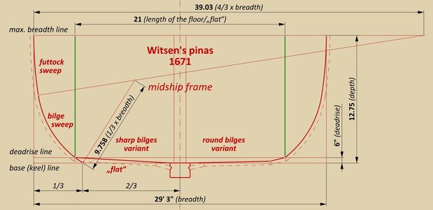
The diagram below shows two variants of the main frame of the pinas, one with sharp bilges and the other with round bilges. Both are possible and both were actually used. The round bilges variant can in this case be obtained in the carpentry way (as opposed to the conceptual-geometric way), i.e. by transversely tilting the last plank of the 'flat' more. In order to keep the co-ordinates unchanged, the 'flat' should be lowered by a few inches beforehand (which is applied here and shown in the diagram).

Somewhat pre-emptively, it can already be said that the coordinates of the hull surface of the pinas given by Witsen were obtained by geometrical methods, however, the position of these points is closely related to the carpentry aspects of the ship's construction and, in principle, this is their exclusive function. To put it another way, the co-ordinates do not necessarily denote the boundaries of the individual geometrical segments that make up the contours of the frames, but the boundaries of the areas of physical planking laid in separate stages of the ship's construction, which is not the same thing.


ViewCapture20230830_000404.jpg

.​
 
Last edited:
Hi Waldemar,

Very interesting again. One question is how do you determine the radia used for the bilge and futtock sweeps, are these retrieved from witsens data?
Is there also a rule of thumb for these depending on the type of ship for instance the fluyt being more square shaped.
 
.​

Many thanks, Maarten. Actually, I have already finished the so-called intellectual part of the work and it only remains to prepare the presentation graphics with the appropriate commentary.

Now, just to quickly answer your questions: Witsen did not give these sweeps radii in the direct way, only the coordination points resulting from the design, which were already intended for the ship carpenters actually building the ship. To put it somewhat metaphorically, Witsen, as a dilettante in these matters, gave, as it were, the result of the 'calculations' needed by the workmen, and not the method of doing these 'calculations'. I will try to elaborate more on this in the coming posts.

I am afraid that there are no 'iron' rules (proportions) here, and the selection of the specific parameters of the ship to be built (such as sweeps radii) was a discretionary competence of the individual shipwrights. Although it is of course possible to speak of certain typical ranges for particular ship types, dictated by their specificities and needs.

For example, for a boxy fluit one would expect a small deadrise, a large 'flat' width, a futtock sweep of a large radius giving almost straight vertical sides, and a bilge sweep of small radius. All this would result in a midship frame shape close to a square. A poor profile in nautical terms, but beneficial for the capacity of a merchantman.

.​
 
Last edited:
.
Do you mean, that when it actually came down to the carpenters(shipwrights) actually having to construct the ship in the shipyard, it still came down to tradition, experience, eyeball and Thumbsup?

:)

Not quite. With the co-ordinates for several leading frames, knowing the various procedures used, possibly having templates at their disposal and under the supervision of the site manager, simple carpenters (meaning: not designers) could certainly build a ship with dimensions that were fully within the expected tolerances, just as today simple construction workers successfully erect buildings even though they have no idea how to design them. And, as a rule, engineers do not personally construct buildings.

It will be also entirely appropriate to point out that this is exactly how shipbuilding was done in France in the 18th and 19th centuries. The designers first of all were expected to send the shipyards the coordinates of the hull in written form (devis de construction), and only on this basis the shipyard workers would trace the contours of the frames on the mould loft. The drawing, even if it was also sent with the written specification, was quite irrelevant because its huge up-scaling was impractical and inaccurate.

.​
 
Thankyou. That gives me a better understanding of what is at work here, a process that is less academic and easier to envision.
I appreciate all of your academic investigations none the less, however ill equipped I am at understanding even a portion of what I am seeing.
My dad, a Yale graduate, (major in physics, one of four in 1941), had a subscription to "Scientific American" magazine and would read it cover to cover each month.
It proved utterly baffling to me.:oops:
We also got "Popular Science". That was for me and my brother. (Dad read that cover to cover as well). I'm still kinda on that level. :rolleyes:

Pete
 
.​

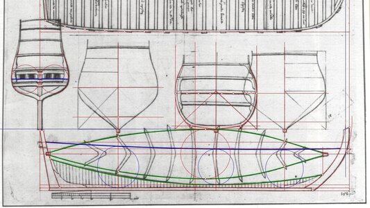
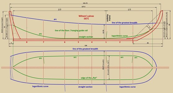
There can be not the slightest doubt that the co-ordinates of the pinas hull given by Witsen in his work must have been the result of a graphic design made on paper. Moreover, of a complete design in the sense that it included, in addition to the main, longitudinal design lines and the contour of the midship frame, also the contours of several other frames, and thus as a whole quite unambiguously defining geometrically the shape of the pinas hull. The precision of this engineering plan leaves nothing to be desired, as the regular geometric curves and their predictable combinations fit the co-ordinates obtained from this plan perfectly.

Whether the execution of this design in graphic form on paper was needed at all is another matter. The point is that design concept of the Witsen's pinas is virtually identical to the extremely simple method of designing the Rålamb's boyer and fluit, already described in previous threads, with their characteristic, almost exclusive use of frame sweeps of fixed radius. The only differences (conceptually insignificant anyway) are the use of a square-tuck stern and the sharp form of the bilges (although this too could have been rounded off in the already described, carpentry-like manner during the actual build of the pinas).

Witsen had most likely seen the plan in person with all its design lines, as he wrote that the lines used for ship design had shapes that were impossible to describe. However, precisely because no one had explained to him how to obtain and actually use these design curves, he had to content himself with putting only measured or transcribed co-ordinates in his work (except, of course, for the rather rough sketches of the pinas, which were not drawn to scale).

The most important conceptual element of the design is the line of the floor, here drawn only on the side view (in green). This line is used to determine the shape and slope of the 'flat', exactly as already described in my previous threads on the bottom-first method. The larger distance between frame #6 and frame #7 is not accidental – this distance separates the straight 'flat' at the middle and front of the hull from the concave 'flat' at the stern (transversely).

On the top view, the line in green marks the edge of the 'flat' (to be sure: this is not the same as the line of the floor on the side view, despite the same colour). In between frames #1 and #6, the 'flat' area narrows solely due to the decreasing width of the keel, as the line of the floor has no rise in this section.

Note: all points in the diagram below (in the form of small circles) represent the co-ordinates of the pinas hull left by Witsen.


ViewCapture20230831_085945.jpg


In comparison, in the drawing of the fluit made by Adam Silo in the early 18th century, the width of the 'flat' (white area) narrows slightly more strongly in this section, which is due to the corresponding elevation of the line of the floor, different from that in Witsen's pinas (note: Silo's drawing captures the specifics of the fluit's shapes quite correctly, but it is not accurate enough to be considered a technical/engineering drawing in the strict sense of the word, it is more of an illustrative graphic):


Fluita - Adam Silo ok. 1700.jpg

.​
 
Last edited:
.​
Thankyou. That gives me a better understanding of what is at work here, a process that is less academic and easier to envision.
I appreciate all of your academic investigations none the less, however ill equipped I am at understanding even a portion of what I am seeing.
My dad, a Yale graduate, (major in physics, one of four in 1941), had a subscription to "Scientific American" magazine and would read it cover to cover each month.
It proved utterly baffling to me.:oops:
We also got "Popular Science". That was for me and my brother. (Dad read that cover to cover as well). I'm still kinda on that level. :rolleyes:

Pete

Pete, what specific venue do you suggest for my publications? Unfortunately, there will always be some advantages and disadvantages of different publishers. At the same time, I am also under no illusion that, for example, all readers of any periodical, even at the highest expected level of content, will in every case be prepared or willing to receive the content provided...

.​
 
Last edited:
Back
Top