
This is all a completely fascinating discussion to me. I really look forward to watching this project progress.

You are using an out of date browser. It may not display this or other websites correctly.
You should upgrade or use an alternative browser.
You should upgrade or use an alternative browser.
Naseby 1655 - reverse engineering the ship model
- Thread starter -Waldemar-
- Start date
- Watchers 26
-
- Tags
- naseby 1655

.
Many thanks, Marc. Honestly, it could already end here, because I have squeezed everything I wanted to know about this model, or maybe better: I have finally learned the method of designing it with all the details (the upper parts of the ship's hull are already conceptually quite irrelevant).
However, your post may provoke me to carry out a more complete reconstruction. Besides, I should redraw the whole thing, correcting the breadth of the ship's hull to the dimensions of the model. I had previously assumed that it had laterally shrunk more because I was misled by the incorrect model dimensions given on the museum website and the rather inconsistent dimensions given by Glete, especially the keel length.
Basically it will be the same, as the whole geometrical construction remains the same, the shape and run of all the design lines the same, and the radii of all the sweeps the same.
.
Last edited:

Waldemar,.
Many thanks, Marc. Honestly, it could already end here, because I have squeezed everything I wanted to know about this model, or maybe better: I have finally learned the method of designing it with all the details (the upper parts of the ship's hull are already conceptually quite irrelevant).
However, your post may provoke me to carry out a more complete reconstruction. Besides, I should redraw the whole thing, correcting the breadth of the ship's hull to the dimensions of the model. I had previously assumed that it had laterally shrunk more because I was misled by the incorrect model dimensions given on the museum website and the rather inconsistent dimensions given by Glete, especially the keel length.
Basically it will be the same, as the whole geometrical construction remains the same, the shape and run of all the design lines the same, and the radii of all the sweeps the same.
.
Your analysis thus far has been breath taking as I've never seen an analysis on a ship like this before. Truly amazing what you've been able put gather from the 3D model.
The level of analysis is exceptionally detailed and it seems you have studied this period of ships for sometime.

Hi Waldemar,
Very interesting topic. I am
Did you also investigated in what timeframe this design process fits?
The ship being from 1655 it was before Anthony Dean who was a revolutionaire in English ship design.
I don't have a lot of knowledge of English ship design methodes but could this design methode also have been used by Phineas Pett for SotS of 1637 which is just 18 years before?
.
Thank you Allegheny. Basically, I am looking for information that cannot be found in Bushnell's simplistic Vademecum 1664 or Dean's equally simplistic Doctrine 1670. As can be seen, the practices of the time were already more advanced than those described in period manuals, and on which today's studies of the subject are mainly based.
Maarten, the variable breadth sweeps are already described in the so-called Newton manuscript c. 1600. It should be added here that, at least in the stern section, their use was even necessary for round-tuck sterns. It is difficult to say whether the Sovereign of the Seas 1637 was designed by exactly the same design method with all its details as shown here, but surely the level of sophistication must have already been similar. However, there are still so many period models to be properly researched...
* * *
OK, now that everything is clearer to me, and in order not to disappoint the expectations of Martes, who also put considerable effort into this as well as other projects (largely hidden in private correspondence), another attempt with already corrected reconstruction graphics.
This time I will use a different approach. The scanned Ö 3 model will be scaled up to the design assumptions of the 1654 programme ships and inversely to the previous diagrams, further on the dimensions will be given for this size, and in brackets for Naseby 1655. If they are not, the given values should be multiplied by 131/120.
To begin with, the reconstructed master frame design. Compared to the preliminary version, it has a larger radius of the lower breadth sweep. Besides, further reconstruction will also take into account Sheldon's correction of his (or his hired employee's) mistake in plotting the hollowing curves already shown above. The irregular contours of the frames at the keel are proof that this mistake was recognised by the model makers themselves and laboriously corrected individually for each frame, but only in the midship area where the angles involved allowed. One by one, using a knife. Not quite neatly.

.
Last edited:

")
.
Right. It's a kind of convention regularly seen on the contemporary plans as well, because drawing a realistic hollowing curve would distort the contour of the actual design of the master frame.
.
Last edited:
I noticed it already and told Waldemar in private correspondence.
Port side:
View attachment 372677
Starboard side:
View attachment 372679
They are still somewhat asymmetric, but closer to the place where they should be.
View attachment 372681
Also, some internal details obstruct the cable entry from the inside in the _new_ holes, so their place is apparently wrong.
As we explained before, that is a question of dimensions. If the dimensions of the model as we know them are correct, and we assume the scale of 1:48, the ship depicted by the model is larger than the known dimensions of Riksapplet as built. (see post #15)
However the model indeed can and probably have incorporated changes from the English original (including deadrise - if the deadrise was not already present on the original - the shape of the bow and decorations), yet I would wait for Waldemar to make at least a preliminary set of lines before looking at this more closely.
I think at least some of the confusion surrounding the subject of this model can be attributed to Donald McNary’s Naseby model (1971), which was based directly on this model of RijksApplet:
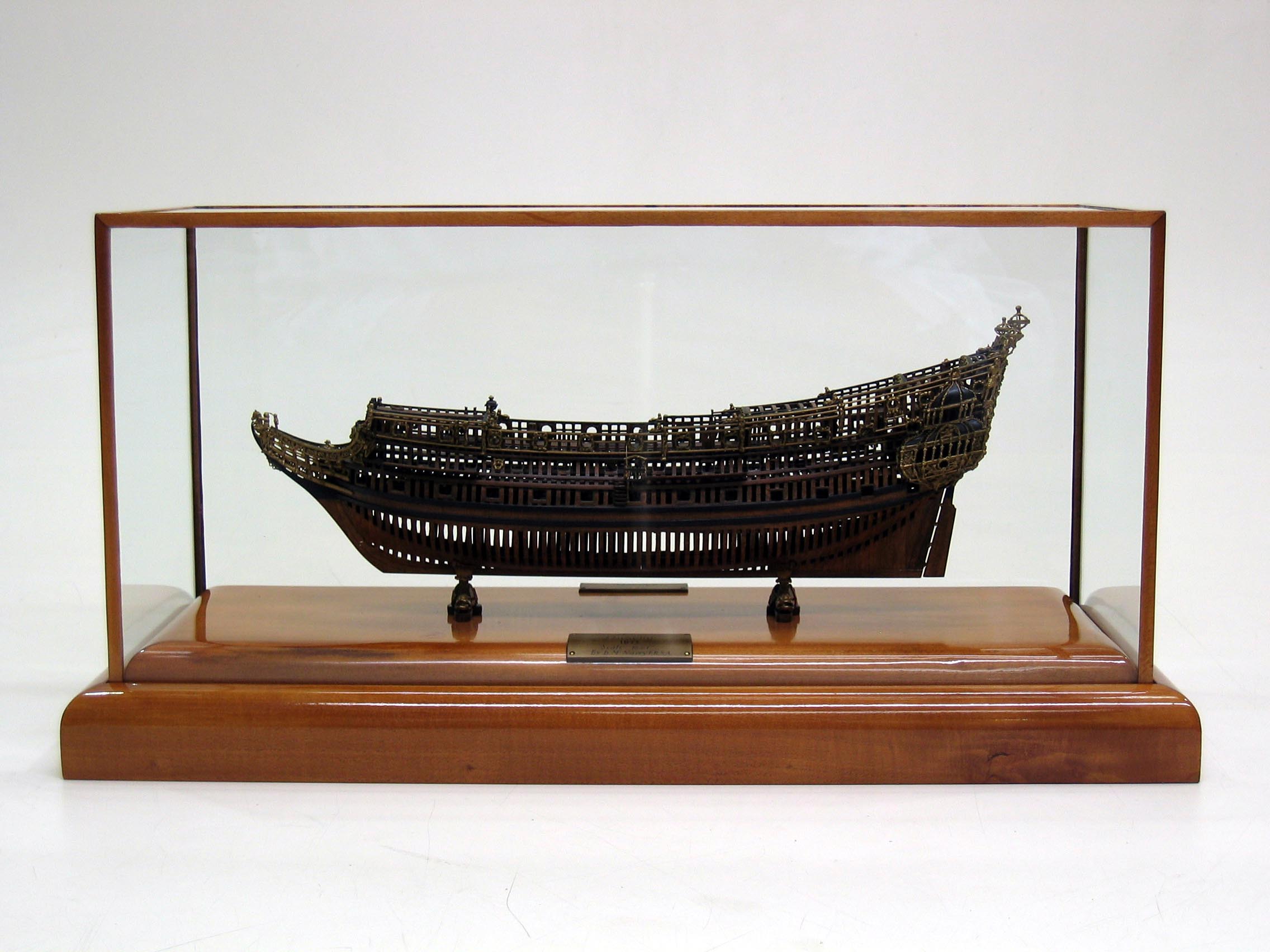
Naseby
By: Donald McNarry FRSA Emulating an original dockyard model found in the collection of the Stockholm National Maritime Museum and so called ‘Sheldon’s Naseby’ model, this scale model is also based on Van de Velde drawings and other contemporary pictures. The 86-gun warship Naseby (131’ on keel)...
www.shipmodel.com
You can see, somewhat perplexingly, that McNary even copied the higher hawse hole placement. Deservedly so, McNary’s work is so highly revered that it can be easy to gloss over the particulars and conflate the one for the other.
And so, it is not surprising that on a surface level the architecture of one very much resembles the other.
.
In a funny coincidence, I also found out today about the existence of another Naseby 1655 model, made already in 1943, and based on the hull lines of the Ö 3 model. It is described here:
.
A question from a layman. Do the lumps in the curve of the frames serve a purpose? Stability? Increased storage?.
Thank you Allegheny. Basically, I am looking for information that cannot be found in Bushnell's simplistic Vademecum 1664 or Dean's equally simplistic Doctrine 1670. As can be seen, the practices of the time were already more advanced than those described in period manuals, and on which today's studies of the subject are mainly based.
Maarten, the variable breadth sweeps are already described in the so-called Newton manuscript c. 1600. It should be added here that, at least in the stern section, their use was even necessary for round-tuck sterns. It is difficult to say whether the Sovereign of the Seas 1637 was designed by exactly the same design method with all its details as shown here, but surely the level of sophistication must have already been similar. However, there are still so many period models to be properly researched...
* * *
OK, now that everything is clearer to me, and in order not to disappoint the expectations of Martes, who also put considerable effort into this as well as other projects (largely hidden in private correspondence), another attempt with already corrected reconstruction graphics.
This time I will use a different approach. The scanned Ö 3 model will be scaled up to the design assumptions of the 1654 programme ships and inversely to the previous diagrams, further on the dimensions will be given for this size, and in brackets for Naseby 1655. If they are not, the given values should be multiplied by 131/120.
To begin with, the reconstructed master frame design. Compared to the preliminary version, it has a larger radius of the lower breadth sweep. Besides, further reconstruction will also take into account Sheldon's correction of his (or his hired employee's) mistake in plotting the hollowing curves already shown above. The irregular contours of the frames at the keel are proof that this mistake was recognised by the model makers themselves and laboriously corrected individually for each frame, but only in the midship area where the angles involved allowed. One by one, using a knife. Not quite neatly.
View attachment 373972
.
A friend recently forwarded to me a doctoral dissertation: Capturing the Curve, The Development of English Ship Design in the 16th to the Early 17th Century by Taras Pevny.
The paper focuses on geometric derivations of hull form, much as you are laying out, here. Unfortunately, for me, Pevny’s analysis assumes a degree of fore-knowledge that I do not currently possess, so I am having quite a bit of trouble understanding the methods he is describing.
Are you familiar with this paper, Waldemar?
.
@Don Case, can you elaborate on what you mean by 'lumps'?
Marc, yes I am, but I cannot promise to be clearer than Taras. There is no choice but to assume some, even basic, knowledge of the subject, otherwise I would have to deal almost exclusively with definitions of various terms and concepts, creating an indigestible monster in terms of volume, at the expense of proper analysis. But fortunately, all these terms are already very well and extensively covered in the literature on the subject.
.
Blue arrows

.
Ah, okay. These are the basic geometric figures (arcs of circles) that define the shape of the frame. They have a specific position and dimensions, at the designer's choice. They are, so to speak, guides for the other geometric sections of the frame, whether arcs or straight lines (marked with a thicker line in the drawing), drawn tangentially to these guide arcs. Of course, the choice of specific values has a direct effect on the nautical properties of the ship. But that is already too vast a topic for this thread.
.
Blue arrows
In a nutshell, the tumblehome (narrowing of the upperworks) is intended to reduce overall top weight, while the bilges (the lower arrows) affect stowage capacity and stability.
Waldemar, can you provide any references for introductory reading on the subject?
.
In this diagram, special attention can be drawn to the way the height of the line of the floor fore is determined (green line). For the last fore frame, i.e. numbered 24, it is eight feet below the line determined as shown in the second sketch. Eight feet is the radius of the floor sweep for this frame.


In this diagram, special attention can be drawn to the way the height of the line of the floor fore is determined (green line). For the last fore frame, i.e. numbered 24, it is eight feet below the line determined as shown in the second sketch. Eight feet is the radius of the floor sweep for this frame.
.
Last edited:
Pictures are worth thousands of words - gotit.  , I will dive-in tomorrow. The Knicks are trying to extend their playoff run, and I am FULLY invested! Thank you for the diagrammatic breakdown, Waldemar.
, I will dive-in tomorrow. The Knicks are trying to extend their playoff run, and I am FULLY invested! Thank you for the diagrammatic breakdown, Waldemar.<duplicate message> I still don’t understand why we can’t fully erase these blips and mistakes.
.
Marc, if you see your needs as more important than my project and what I would like to show, and cannot wait with them, I have good news for you. Dr. Kroum Batchvarov has just opened a sort of information centre for modellers. He is here and it is hard to imagine a better reference. Why don't you take advantage?
I'm also glad you found a good place to write about the Knicks, whatever that is.
.