

.
With the encouragement and help of Donatas and Martes, I decided to attempt to reverse-engineer the design lines of an attractive mid-17th century model of a ship now in the Maritime Museum in Stockholm.

Link to the museum's page with a description of the model:
Link to scanned 3D model:
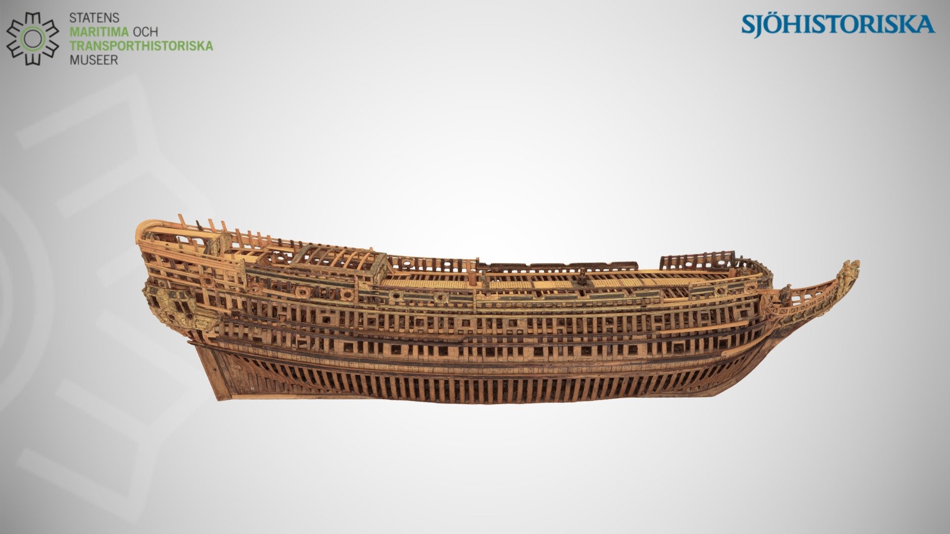
Three-decker (c. 1660) - Download Free 3D model by SWEDISH NATIONAL MARITIME AND TRANSPORT MUSEUMS (@maritima)
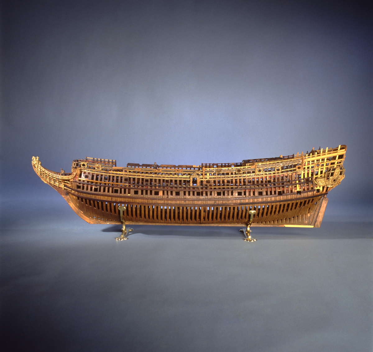
This unplanked model of a three-decker can be dated to c. 1660 and is one of the world’s oldest models of a warship. Although not definitively identified, recent research links it to the Swedish ship Riksäpplet, designed by the English master shipwright Francis Sheldon and launched in 1661...
 sketchfab.com
It has been accepted that the model represents the English ship Naseby 1655 at a scale of 1:48. The recorded dimensions of this ship (as built), according to British Warships in the Age of Sail 1603-1715 by Rif Winfield, are 131 feet (keel) x 42 feet (breadth) x 18 feet (depth in hold).
* * *
Edit:
Summary
An attempt to reconstruct the design concepts of the Ö 3 model has been completed, with the process and methods used shown later in this thread. Its results can be considered an excellent complement and even correction of information coming from contemporary written works on shipbuilding (notably Bushnell's Vademecum 1664 and Deane's Doctrine 1670), which, as it turns out, are simplistic and even outdated in terms of the design practices already in use at the time.
As far as the identification of the model itself (so far uncertain) is concerned, in the briefest of terms, its read proportions perfectly match both Naseby 1655 and, most likely, the wreck of Riksäpplet 1663.
The analysis also showed that the size difference between the two ships is solely due to the difference in length between the English foot and the Swedish foot (304.8 mm and 297 mm respectively). In other words, apparently both ships were built to the same design and even the same nominal dimensions, just using different length units. More on this later in the thread.
In this context, it should also be added that the configuration of the upperworks (with its decorations) is considered an incomparably weaker interpretative 'argument', as it could (and indeed did) change frequently during the life of the ships and, besides, did not necessarily correspond to the original design from the beginning.
For the convenience of readers, the reconstructed plans (hull lines) of the Ö 3 model in modern convention are again attached below as a ZIP file, both as a high-resolution raster and in vector format. Both saved as PDF or JPG. Besides, a low-resolution preview of the content:

.
Attachments
Last edited:

")


