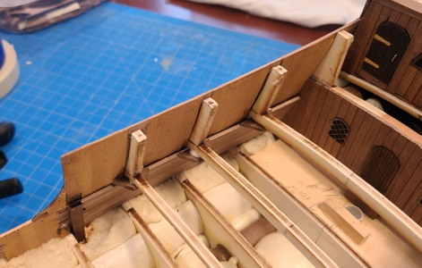
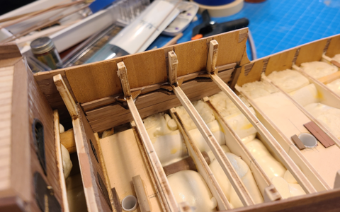
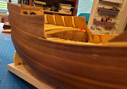
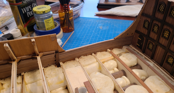
MarisStella Ragusian Carrack by Signet [COMPLETED BUILD]

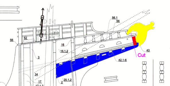
Working next on the extension under the bowsprit (bowsprit deck? stem? I'm not sure). Looking at the figurehead provided (as well as the drawings of the carved version in yellow), I felt that part 43 (in red) was not large enough to provide a backing for it:
1681659607274.png
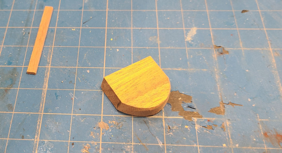
Also, the curved end of the blue extension (again, I don't the name of it) interferes with the figurehead (Olha sanded hers off as well). I decided to cut the blue part at the purple line, and add another piece to part 43 to make it higher:
1681659881923.png
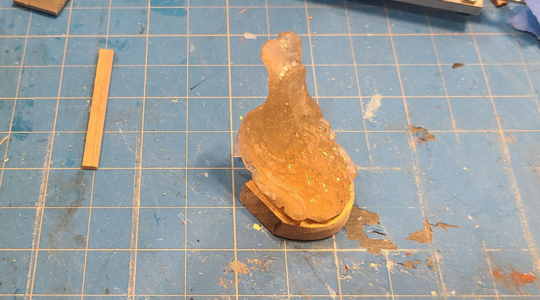
This seems to fit the figurehead much better:
1681659909550.png
In fact, it wouldn't hurt for it to be a bit higher yet.

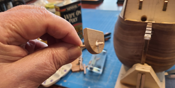
Since the mounting/gluing area for the modified part 43 is less, I decided to add a toothpick pin to help locate and strengthen it:
1681660008781.png
This was a whole lot easier to keep in place while the glue dried than any kind of clamping would have been:
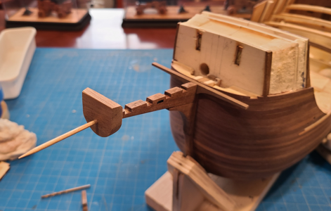
1681660063954.png
Maybe a simplified USS Unicorn figurehead? o_O

The transition from rounded hull to straight bow extension results in a gap under the extension. I had some leftover planking pieces that I used here (partly finished in the picture):
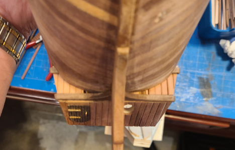
1681660218035.png
You can see where these go in from above:
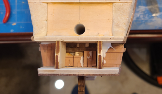
1681660270603.png

The remaining bowsprit floor supports have now been added:
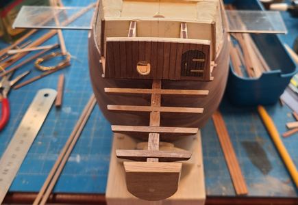
1681660334917.png
To make sure they're parallel to the rest of the model, I use a Level app on my smartphone. I placed a straightedge across the hull, placed the phone on it, and Zeroed the level reading, then placed it over the supports and adjusted it to zero, so they are parallel. I've used this method for a number of things, like setting angles on my sander and such, and it works very well.

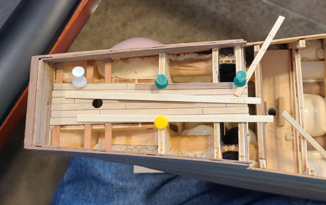
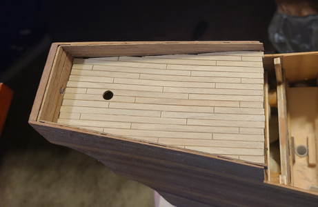
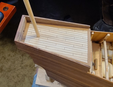
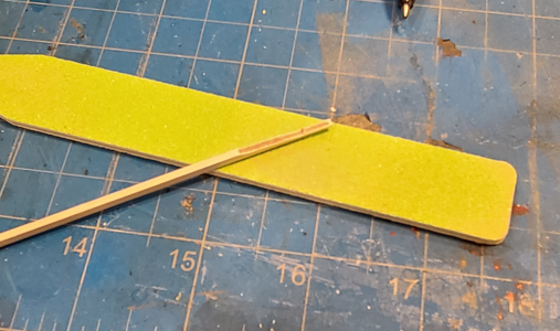
Even though I've only added on plank to this assembly so far, I decided to deviate and work on the detail of the deck area and gratings, figuring they would be more difficult to to work on after the side planking was done. Also, I was avoiding making a couple dozen straight and perfectly tapered planks as long as possible.

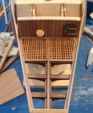
I made up gratings (more about the material used later) to fit openings which were mounted around the floor area. Since gratings should never end on an "opening", I made them a bit narrower (left picture) to allow for another strip (shown in right picture):
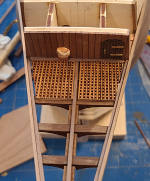
1681660598240.png1681660617968.png
The added strip is of the same material, but is just glued to the side, because of course the notches don't line up when mounted at an angle:
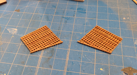
1681660668866.png

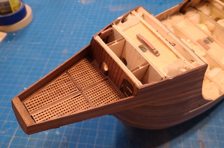
The four mounted gratings end up looking like this:
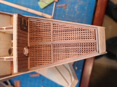
1681660706441.png
Those with sharp eyes may notice that the lower hinge of the door, which I lost months ago, has magically appeared in my desk drawer, and has been mounted to replace the hand-made substitute shown above. I didn't like the variation in wood color on the above, so sanded the tops and recoated with varnish, cutting the slots for the stropping at the same time:
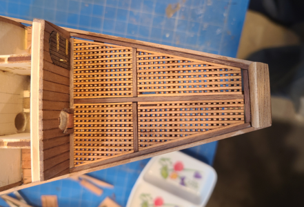
1681660862117.png
Much better, I think.

Concerning the grating, I'll do a mini-review of the grating I used here:

Model Shipways Cherry Wood Grating Strips 12 x 3/64 x 3/64"Laser Cut 8 pack
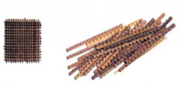
1681662637332.png
(Poor screenshot from their web site, corrected for distortion)
They look like this, delivered in a tube of 8 pieces, each 12" long:
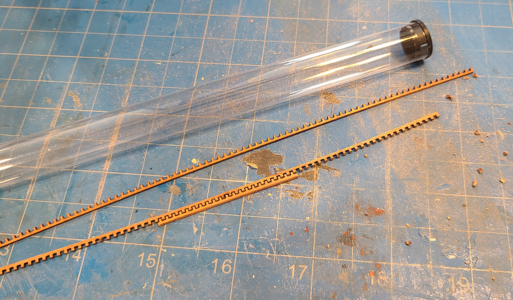
1681662720056.png
They are laser cut of cherry wood. The wood is fine, but laser cutting causes 2 problems: Lots of char to remove, and a pretty loose fit. I think most other (non laser cut) gratings are machined, which makes for a tighter fit. Anyhow, my opinion on these:

Pros:
  • Cherry wood is a nice alternative to very light woods usually used.
  • 12" length makes for larger gratings without piecing and less waste.
  • Pretty economical (I think - hard to know how much is included in other gratings), at least you can figure how much to order.
Cons:
  • Char must be removed by sanding both sides, which can easily break them.
  • Even after sanding each strip individually, remaining char can vary, changing appearance. I recommend sanding after assembly.
  • While the laser kerf is small, it's still there, making these fit together much more loosely than other gratings. Therefore, they're constantly falling out of the assembly as you're working on it, or even turning at an angle. Much more troublesome than machined gratings.
That's it for today. Guess I have to figure out how to taper all those planks so precisely. :(
 
Lookin' good Signet. The gratings make the area look very nice.
Thanks. I like them better than the open spacing described on the plans. I should have given Olha the credit for including the small grating grid as done here, as that's what she did on her model. I think the extra pieces I added on the slanted side of the grids looks good, though, and should be more accurate.
 
Continuing on with the bowsprit area, I can now complete the hull planking.
1681824271430.png
The small step pieces of scrap wood around the hole for the foremast are for supporting planking around the mast. I've now done this around all the mast holes, so that deck planking is held at the right height when there is no other support around them.

With the grating in place, it starts to look more finished:
1681824489812.png

Underneath, the areas filled with scrap planking can be seen:
1681824555619.png
No, they're not very neat, but neither are they very visible.

Another view of the completed planking around the stem:
1681824610761.png

While looking at the photos, I went back and took some measurements, and found that while I used less number of planks, the height of the foremost portion of the stem, where the columns will mount, was too high, no allowing enough height for the columns, so I went back and took off the topmost plank. I'll refinish it later:
1681829964714.png

I'm trying to decide on what to do next. Olha started planking the stern, but then she already had the rubbing and other strakes in place, and I don't. But I'd like to mask off the hull for painting the bottom black while the lowest rubbing strake is absent, as it will be easier and more accurate for me to do that way. I'll just have to see where I go next.
 
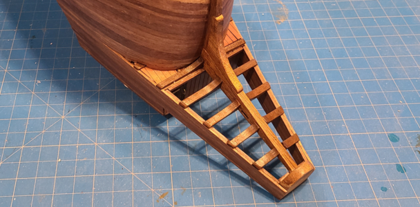
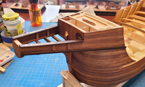
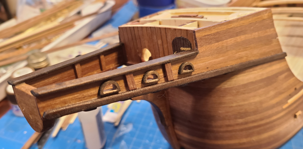
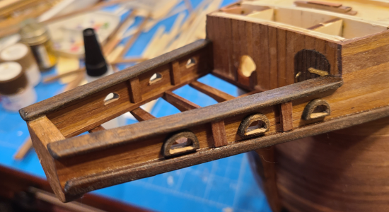
While I'm not adding most of the rubbing strakes and others at this time, I wanted to strengthen the stem extension under the bowsprit better, add some detail there and see how the contrasting colors would look. I started by adding the 2x4mm piece at the bottom:
1682180121266.png

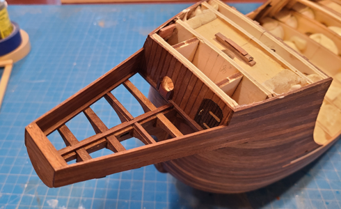
I then added the 2x7 rails attached to the top, forming the lower portion of railings in this area:
1682180174914.png

After adding some bracing, the result starts to look a bit more finished:
1682180223892.png
(I straightened the brace on the right after seeing it in the photo. Surprising how many problems & errors I see in the photos.)

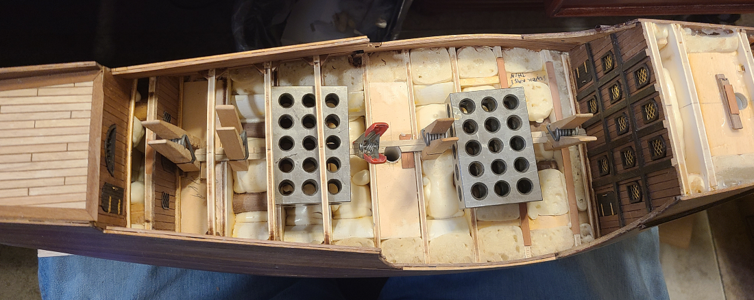
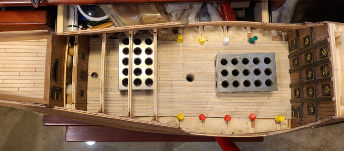
Time to start looking at the inside of the bulwarks and deck planking. I chose the easiest first, the poop deck. This photo shows the bulkhead extensions removed and where 1/64" veneer was placed between them for strength (neatness doesn't count here - it's still stronger and will all be covered):
1682180314822.png

I started at the top with the inner planking, and used 0.6x4mm walnut strips for this, which I bought separately, as the kit is intended not to have an extra thickness here. I think it's supposed to look like the same, thicker plank inside and out:
1682180547527.png

Inner planking is done, ready for decking. The two layers of walnut, plus the veneer at right angles, really strengthens the walls.
1682180461258.png

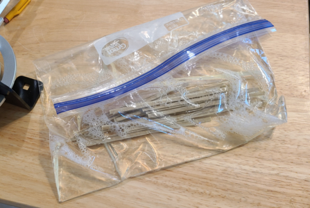
I wanted my decking to be lighter than the main structure, for contrast, because most decking I've seen is quite weathered, and scrubbed, and sun-bleached, but had no light wood to use. I decided to bleach the walnut strips I had using Clorox bleach, rather than sun. I had experimented before with a couple small pieces, and it looked like they would work, so cut strips for the poop deck, placed them in a plastic bag and filled with bleach:
1682180825688.png
I forgot how long my previous pieces had been allowed to soak in the bleach. I had intended a half hour, but forgot about them, and it ended up several hours. I closely watched the above, and decided to go with 2 hours, as it was still lightening.

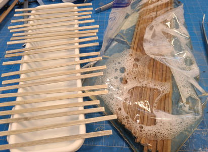
Here are the bleached short 2 hour strips along new strips for the main deck just being soaked in bleach:
1682180967932.png
At this point, the short strips seemed okay to me, and I was trying to compare them with the ones being soaked.

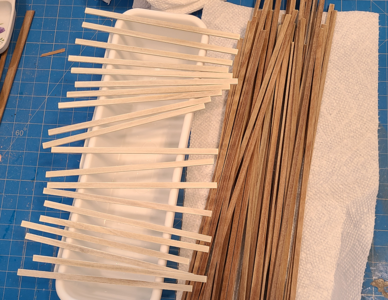
I realized at about an hour that the previously soaked-for-2-hours strips were getting too light, so at just under an hour, took the longer strips out of the bleach. Here we have the very light short strips, and freshly soaked 1 hour long strips:
1682181119253.png
It's obvious at this point that the strips continue to bleach lighter, even after being removed from the bleach, rinsed with water and dried off.

After being soaked for 1 hour and left out for only a few minutes:
1682181245925.png

And after 8 hours:
1682181272744.png
I liked the way the long strips were going, but the short ones are too light IMHO.

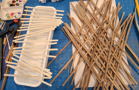
So I soaked new short strips, but this time for only about a half hour. Right after soaking, they look like this:
1682181342437.png
Newly soaked short strips are in the center, horizontal. Previous (too light) short strips on the left, and long, soaked okay, strips on the right.

After about 8 hours, again, the new short strips have lightened more:
1682181433011.png
They match the previous long, 1-hour strips pretty well, so I will be using only a half hour soak from now on.

I'm not very good at filing or cutting deck planking around masts and other round objects, but needed a hole in the poop deck for the bonaventure mast I would like to install, so made a little fixture to hold two planks together while I drilled a hole for the mast using a brad point drill in my drill press:
1682182161377.png
I've pre-cut all decking pieces with slots for plank length's using a 1-3-2-4 spacing. I had previously experimented with treenails, but didn't like any of my results, so decided to not use them. I'm happy with the clean look of the planks this way. I also beveled the edges of the decking a bit to help them stand out.
1682182336659.png
As you can see, I used some of the scrapped too-light and treenail practice strips as protection when nailing strips in place.

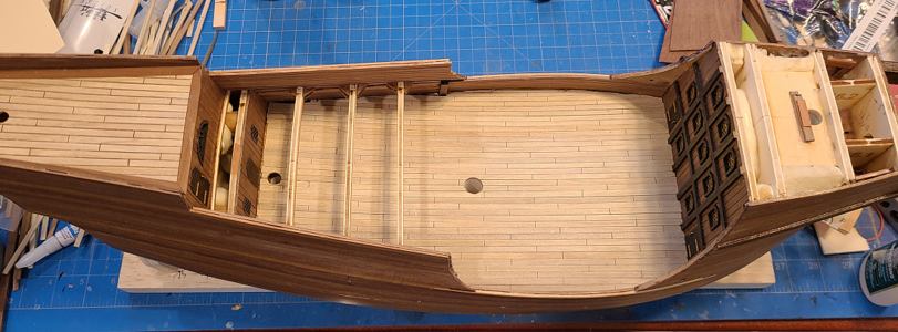
The planking is now complete:
1682182425021.png

And the end result with the waterways/edging and bonaventure mast in place:
1682182457191.png

Unless I want to do other hull details, the main deck is next, but I have to consider how much, if any, of the side of the bulkheads I will be removing first. Either way, it's going to be a pain, as I'm leaving the quarterdeck support beam portion of the bulkheads in place.
 
Last edited:
Wow! That bleaching thing is a wonderful revelation to me. Can you cut a strip and show me the inside? I'm wondering if the bleaching is consistent through the thickness/depth of the wood.
 
Wow! That bleaching thing is a wonderful revelation to me. Can you cut a strip and show me the inside? I'm wondering if the bleaching is consistent through the thickness/depth of the wood.
No, it's not. It bleaches the outer surface more. Of course, I'm sure that depends on how long it was soaked, and maybe how thoroughly it was rinsed afterwards:
1682201445794.png
In my early experiments, I was able to actually sand the corners slightly and have it darken, and prick pin holes and have them look dark as well. That might be ideal, but not the way my strips came out and I can't waste any more wood. The cut slots to delineate ends of planks does show up well because it's getting into the core of the wood.

As stated, the bleached surface can work to your advantage. If you need to cut or machine a good bit from the wood, and want it light, just do the woodworking first. Anyhow, I'm pretty happy with the result, and it saved me a lot of money vs buying new wood for all the decks.

Another thing that can work to your advantage is that any variations in the grain are much less visible after bleaching; in some cases "real" wood grain looks way out of scale with "scale" wood grain, so this can help. It all depends on the effect and color you're going for.
 
Last edited:
No, it's not. It bleaches the outer surface more. Of course, I'm sure that depends on how long it was soaked, and maybe how thoroughly it was rinsed afterwards:
View attachment 370701
In my early experiments, I was able to actually sand the corners slightly and have it darken, and prick pin holes and have them look dark as well. That might be ideal, but not the way my strips came out and I can't waste any more wood. The cut slots to delineate ends of planks does show up well because it's getting into the core of the wood.

As stated, the bleached surface can work to your advantage. If you need to cut or machine a good bit from the wood, and want it light, just do the woodworking first. Anyhow, I'm pretty happy with the result, and it saved me a lot of money vs buying new wood for all the decks.

Another thing that can work to your advantage is that any variations in the grain are much less visible after bleaching; in some cases "real" wood grain looks way out of scale with "scale" wood grain, so this can help. It all depends on the effect and color you're going for.
Thank you kindly. I learn something almost every day on this forum.
 
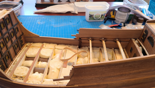
I decided to complete the inner planking (not in the plans) before making any hull openings for guns, etc. This makes it stronger, and helps maintain the correct shape and contour of the unsupported upper hull.

I decided to remove the side portions of the bulkheads between the main deck and quarterdeck, but keep the horizontal portion as quarterdeck supports. To me, it seemed a shame to have the proper quarterdeck location determined by the bulkheads, but then remove them and replace them with hard-to-form curved members at different spacing. The downside is that it is not as strong (but I will address this) and and the stairway in the quarterdeck has to be moved slightly, as shown below:
1682434583654.png
I don't see any problem with moving the stairway slightly, so decided this was okay.

After removal of the sides of the bulkheads (mostly with a sharp chisel), I started laying the inner planking from the bottom up. Unlike the poop deck sides, on which I had used 0.6x4mm planking ordered specially, I used the same 1.5x4mm planking as on the outside because 1) I now felt I had enough of this material and 2) felt it would make the whole assembly stronger. In hindsight, I should have used the same thing on the poop deck. The sides of the hull above the quarterdeck tended to bow outwards due to gluing, and I was determined to bring this back in line, strengthen and straighten it.
1682434804123.png
The red arrows show where the sides of the bulkheads were removed. As you may recall, I added thin veneer vertically to strengthen this area, but could not located it at the bulkheads. The planking will cover both, of course.

Here the planking continues up on both sides:
1682434952634.png
Since the bulkhead just aft of the main mast did not extend to the quarterdeck, I had to provide both a vertical support (shown) and curved quarterdeck support (currently removed) to support the deck. It will also be the only one visible.

This is about as far as I can extend the inner planking, as I want to provide extra support for the quarterdeck cross supports:
1682435095684.png
The cross supports are pretty flimsy: the material is rather soft and easily broken, and I've removed the main support below them, so need to attach them better to the side walls. I did this by first adding gussets below each cross piece:
1682435189204.png
I then added pieces in between the cross beams as well as triangular gussets:
1682435242626.png
These supports are all in actual ship construction, they just look a lot better and neater, but in my case this will all be invisible.

To see how visible the gap left as well as the sloppy gussets will be, I took a photo at about the only angle they will start to be visible:
1682435335192.png
Sorry, my phone wanted to focus on everything except what I wanted it to. But as it shows, only a very small portion of the gap is visible from this angle (in red, with an arrow pointing to it). And with decking added later putting the entire area in shadow, it should not be at all noticeable. Yeah, I like things to be "right" too, but can't see spending /too/ much time on something that you cannot see when the model is complete.

I then added the inner planking up to the rail, stopping just below it. Planking above it, on the curved portions, will be added after the rail is in place.
1682435550137.png

Finally, the sides of the bulkheads above the quarterdeck have been removed (I had previously made shallow cuts at either side at deck level to help ease this process and make it neater), and inner planking added to this area:
1682435649580.png
Yeah, it's sloppy, but most of it will not be visible.

I was tempted to put a coat of clear on the inner planking, but want to put the vertical supports in before that. And those supports have to have cleats and rings mounted on them, so I have to figure out where they will go and such. Guess that will be for next time.
 
Last edited:
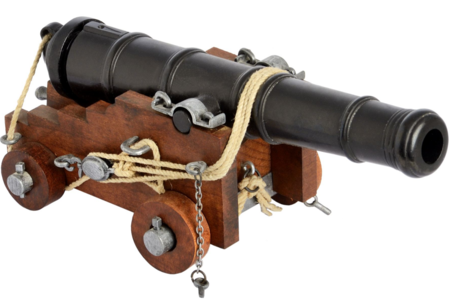
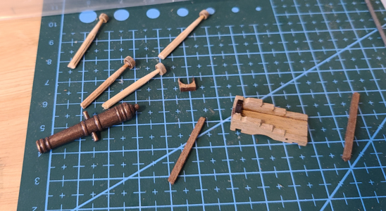
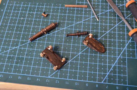
I'm not one to blindly put things like gunports on a model without confirming where they should go, and in particular, how high they should be. Even if my outer planking and rubbing strakes aligned exactly with the deck planking and waterway, I've seen too many variations in gun carriages and barrel angles that can end up causing problems. So, even though it's a bit early, I thought I'd cobble up a couple guns for this model so that when measuring for gunports, I'd be all set.

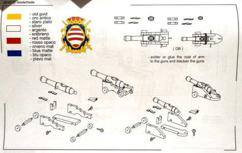
MarisStella's instructions show how each of the gun sizes/types is assembled:
1682476738638.png
The suggested method requires assembling the side brackets and floor to make a U shape, and then sawing or filing out slots for the square stock to be used as "axtrees". The trickiest part IMHO would be rounding the ends of the axtrees to fit the trucks (wheels). Like Olha, I thought that using round, tapered toothpicks might work better, especially since they cannot be seen once mounted to the carriage.

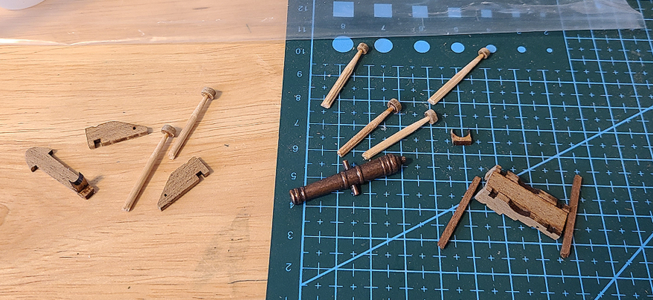
In my case, I chucked half of a toothpick in a drill, and sanded the diameter to be smaller, to fit into the slots in the brackets:
1682476992558.png
I used CA gel to attach the trucks to the toothpicks, then chucked up the combination in a drill to take the char off the outer diameter of the trucks. The outer end (small end for me) was sanded to allow a little of the round portion of the "axtree" to extend, and I cut the larger end to be the same length as the thickness of the brackets. Olha drilled holes in the carriage and used the pointed end to insert, but I saw no advantage to that for me. As can be seen above, it would be time consuming to provide slots for the square axtrees. I also didn't bother to contour the bottom to the side radius of the brackets, as they will not be able to be readily seen.

1682477407648.png

I just glued the larger end of the toothpicks into the bracket recesses, with the trucks touching the brackets:
1682477473800.png

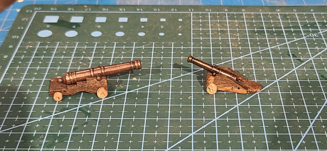
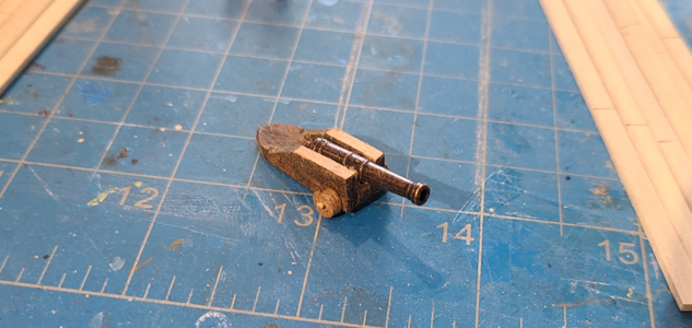
Here we have the result of the bare (non-detailed) guns with barrels in place:
1682477515126.png
Notice that the smaller gun in particular has way too much loft. The instructions show wedges used for both to position the barrels at the desired angles. I'll determine them after the gun deck is in place to see what is best. As noted on the instructions, and shown in Olha's videos, the smaller guns have rope wrapped around the barrel and carriage.

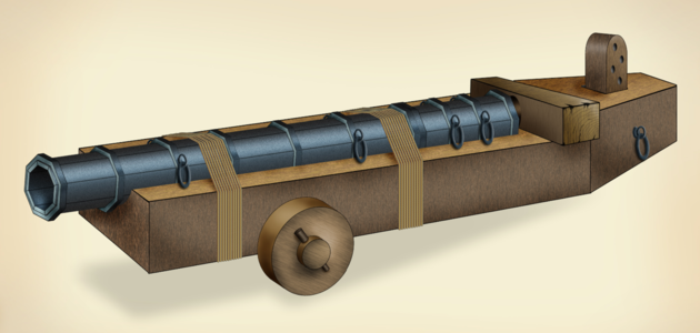
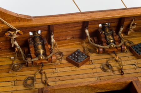
Question: I've seen very early naval guns with bare barrels held to a frames with rope, but never with the barrel having trunnions. What is the purpose of the rope in addition to the trunnion? I can see none. The trunnion allows vertical pivoting, with the wedge determining and maintaining the angle, but neither works with rope holding it in place. Would the whole 2-wheeled carriage have to be then lifted to change the angle? Here is what Olha's guns look like after installation, showing the ropes in question (VERY neatly done, naturally):
Can anyone tell me the purpose of these ropes and how the work or interact with the trunnion? I've searched and cannot find this type of naval gun with ropes.
 
Last edited:
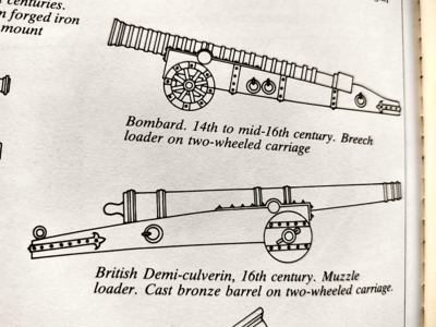
The ropes are acting as capsquare, they are holding the barrel to avoid 'jumping' from the carriage while firing. Depending on the period, this could be a 'Port piece' or 'Sling\Demi-sling' or bombard type of gun. If this is true, they should have a hole at the end of the cartridge. In this hole, you will put a wooden stick pierced with holes. when aiming the gun, choose the required hole on the stick and secure it with the pin.

1682482305355.png
 
The ropes are acting as capsquare, they are holding the barrel to avoid 'jumping' from the carriage while firing.
That's what I had assumed. But then there is no reason for the trunnion on the barrel. Or rather the ropes prevent use of the trunnion, as I mentioned above. The instructions show this gun having trunnion, capsquares AND ropes. Confusing, this is.
 
That's what I had assumed. But then there is no reason for the trunnion on the barrel. Or rather the ropes prevent use of the trunnion, as I mentioned above. The instructions show this gun having trunnion, capsquares AND ropes. Confusing, this is.
I assume the kit manufacturers have a so-called 'Artistic license' where they can represent things in their own view not close to the original. This can be dictated by multiple reasons, one of which is poor research or limited documentation available. Another one could be the reuse of the existing barrels (from a different ship kit). It is possible that you have a culverins?

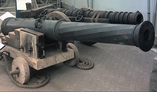
Below is an example from the same era where even the larger guns don't have trunnions

NavalGun.png
 
I assume the kit manufacturers have a so-called 'Artistic license' where they can represent things in their own view not close to the original. This can be dictated by multiple reasons, one of which is poor research or limited documentation available. Another one could be the reuse of the existing barrels (from a different ship kit). It is possible that you have a culverins?
Yes, that's possible, in which case I question the fact that the included barrels include trunnions. Perhaps the trunnions should be removed, and possibly the brackets lowered, to be more like them.

As to artistic license by the kit manufacturer, that's very possible, and most kit manufacturers always bump up against a limit of true scale and appearances versus part availability and cost, but it would seem to be more consistent to have the same type of carriages with such similar barrels.
Below is an example from the same era where even the larger guns don't have trunnions

View attachment 371410
The gun in the background appears to have the barrel fixed (non-movable) to the carriage, as I believe is normally the case with a culverin. The gun in the foreground has a carriage like most guns with trunnions, as the steps are used to raise and lower the barrel with pry bars. But as you say, there is no trunnion on the barrel. Possibly it rests on the iron bars mounted horizontally in the carriage? Or an earlier barrel was placed on a later carriage? I really don't know.
 
If you were to compare the gun in the background with the one in front, you would notice that the 'front' barrel is much bigger in size, but... the bore is much smaller compared to the one in the background. I suspect the shots are relatively small and with their own weight it will not jump while firing. The front one is cast from bronze, and the one on the background looks like iron.
 
I asked Zoran of MarisStella about the roping on the smaller guns of the quarterdeck, and this is his response:

This is a typical middle age the two wheeled carriage. The barrel that were in use were or the rock firing or typical classic metal balls firing barrel…

In the museum is the carriage exactly like we have drawn in the project.

The gun was held to the carriage by trunnions. But these were light barrels, bumping on the carriage while the ship was on the sea. The barrels would often release a Quoins that would fall onto the deck and the barrels would literally bounce in the carriages. Fastening with ropes was a neat daily practice on old sailing ships. Almost all major items on all decks were tighten by ropes.

While not in use, light barrels were roped to the carriages to hold them tight, not bumping in the carriages. There was a Quoin (triangular wooden block with a handle) below the barrel rear end.

He also included a number of photos of guns with roping in place:
1682650948883.png
The top two guns have barrels that are definitely held in place, permanently, with ropes IMHO. No trunnions are used.
1682650987304.png
Here we have trunnions without ropes.
1682651017284.png
1682651063724.png
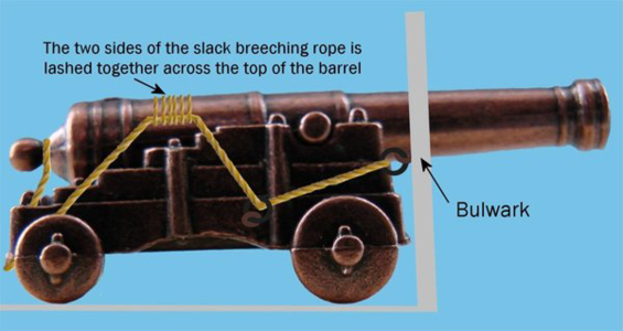
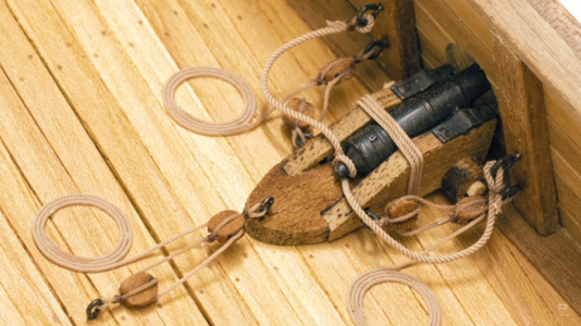
The above roping mostly serves to store the tackles out of the way, but will also tend to hold down the barrel.

1682651104494.png
Same here, mostly to remove slack of breeching cable.

I'm not sure that the method used by Olha and shown here:
1682651434058.png
serves the same purpose. Obviously, this won't hold the gun in place, but does hold the barrel down. It also would be difficult to tie without any loose ends and tends to look permanent.

We tend to model our ships with guns ready for "use", rather than stored for rough weather. Otherwise, the barrels would not be extended through the gunports. I guess I'm still undecided as to how to model these guns. If the lower guns aren't modeled with any kind of retaining ropes, I see no reason for the upper guns to be.
 
I was looking again at the build of this Ragusian Carrack by Jack Aubrey here on SOS. In his excellent review and build he has quite a few photos of the original model sent to him by Zoran Pavlovic of MarisStella. The larger guns on the lower deck are pretty much the same as we know from most ship models:
1682706827407.png

The smaller guns on the upper deck, however, are modeled a bit differently:
1682707065868.png
This is more what I would describe as a culverin, although I realize that technically that had more to do with size than style. But I have definitely seen photos of versions similar to the above where ropes and a backing board are used to hold the barrel in place, rather than a trunnion, and where the entire barrel & carriage assembly would be elevated using a wedge or quoin, rather than just the barrel within the carriage.

So - I intend to make my model much like the above, which I believe is what was originally intended, but possibly due to barrel availability only with trunnions was modified in the kit. I can simply cut off the trunnions, sand off the top of the brackets and add a backstop to take the firing forces. And of course, add the roping to hold the barrel in place. The shape will be more like this:
1682708111582.png

In the meantime, I've been planking the main deck. As before, I bleached the walnut 1.5x4mm strips using bleach, and pre-cut the plank length lines to simulate the 1-3-2-4 planking pattern:
1682708232531.png
Since it is difficult to measure plank length and have them fit well, I will be starting at the forward (more visible) end, and have by trial and error made a "reference" strip length. I then put it in place, and using it as a measurement, make the other strips slightly shorter or longer as required.

Starting at the middle of the deck:
1682708571351.png
1682708612268.png
And this is where I am now with the planking:
1682708636733.png
Time to go feed my son's cats, while they are enjoying themselves at Disney. :)
 
Main decking is now complete:
1682819180645.png
The exposed area to the front is pretty neat, I think. The jagged area toward the back will be covered by the quarterdeck and pretty much impossible to see. I know, that's a cop-out for poor craftsmanship, but I've gotta spend my time and effort where it's most visible.

Laying out the centerline location of gunports, "drains" and futtock riders:
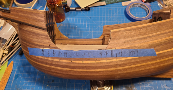
1682819246306.png
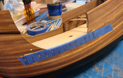
After doing it so many times on the wood to be covered by the rubbing strake, I decided tape was a better idea. Looks like the holes I drilled for drain ports aren't in the right place. I have to decide if it will look better to fill them and position them correctly, or mount them in a different location.

A quick trial tonight with some MinWax Color-Matched Wood Filler (in Golden Oak, quite surprisingly) provided a good match and made the holes disappear, so putting them in the correct position is the way to go.
 
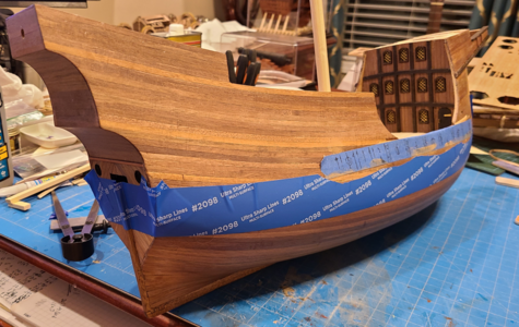
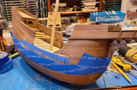
I decided to paint the bottom of the hull black, and wanted to do it before rubbing strakes and other hull protrusions were installed, as masking would be much easier. Since the division of hull painting does not match the waterline, and is not straight, in this kit, I referenced it to the lower rubbing strake location amidships, then up at each end the proper amount, and added masking tape by eye:
1683129013344.png
1683129048426.png
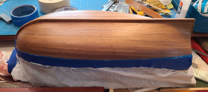
I then taped a portion of a plastic bag to the edging tape to protect the rest of the model:
1683129105348.png
Not shown, but I inserted a dowel piece in the hole for the mainmast to use as a handle to hold the model while painting.

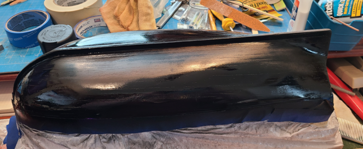
The result right after painting:
1683129195944.png
There are many imperfections, some I may fix, but they are less noticeable once the flat black paint has dried. Most of the paint edging worked quite well, but I'll have to touch up around the keel a bit at the stern and stem, after everything is completely dry.

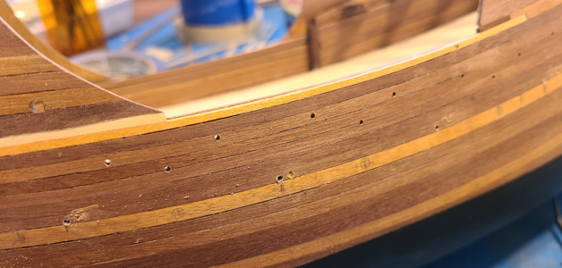
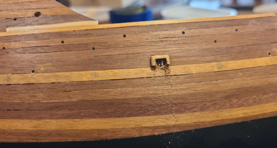
After removal of the masking tape, and allowing the paint to dry thoroughly, I wanted to permanently mark gunport, drain & futtock locations. The tape I had applied worked well to locate them, but not permanently. I decided to drill a hole at each location:
1683129392503.png
Each hole is centered about its intended feature. The drains are right above the rubbing strake and enter the inside just above the deck. The gunports are centered side-to-side, but height will be determined by the deck and gun height. The hole at the futtocks go through and will be used to also locate the inner reinforcement pieces. So each hole marks the exact location of a feature, allowing it to be added precisely later.
1683129553328.png

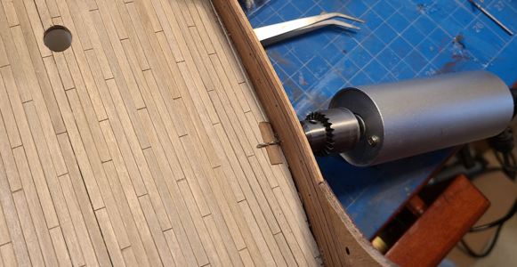
When drilling the holes for the drain, I placed a small piece of waterboard material above the deck; ideally, the hole will be just above the rubbing strake on the outside, and just above the waterboard on the inside.
1683129627248.png

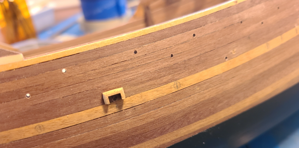
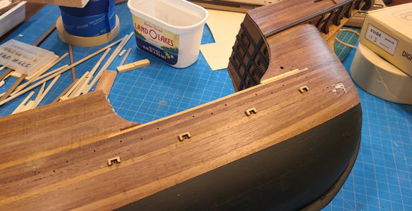
Everyone else I've seen putting drain surrounds and gunports in, including Olha, have marked the location, made the hole in the hull, and added the surround afterwards. I wanted to try a new method: Gluing on the surround (having sanded the outside, but not the inside) before enlarging and sizing the hole:
1683129783752.png
In this case, I am using the hole made previously to locate and center the drain surround.

After the glue has dried, I then drill multiple small holes for the opening, using the inner outline of the surround as a guide:
1683129754152.png
Filing then completes the opening and smooths the inner part of the surround at the same time, and obviously everything is in line this way.

Once that test worked okay, I located the remaining surrounds:
1683130003977.png
While it would have been nice to have the rubbing strake that goes right below these openings in place to help locate them, I felt the strakes would be damaged during filing. Doing the openings first protected the strakes, and now the strakes can be applied directly under the openings using the surrounds as a guide.

I used the same method (applying the surrounds first, then making the openings) on the forecastle:
1683130181862.png
1683130212690.png

To help make the openings even, I placed a piece of light colored paper behind each opening, and fine-tuned the outline:
1683130262857.png
This makes any variations very visible and easy to correct.

I will later re-stain the dark areas and apply finish again where it has been removed, but will wait until later.

I started bending the 2x4mm strakes that need to be added, with limited success. I think I'll try boiling water instead. Also, I like the idea of brass nails located along them, and doubting my skill at adding these later, I think I will pre-drill the strips before bending, staining and mounting. I also hope I can then use the nails to help locate and hold the strakes in place while the glue dries.

So I'll probably be a while figuring out how best to precisely drill approximately 300 holes in these strips. I'll no doubt show you how I make out next time.
 
Last edited:
Well, my problem ended up more about how to bend the rubbing strakes in the bow area than about drilling the holes. As to the holes, I decided to "bolt" the strakes in place, as much to help hold and nail them in place as to have bolts displayed (brass, in this case - maybe not authentic but in keeping with other brass areas I am keeping). The first task was to decide what size brass nails to use to simulate them:
1683429186698.png
While I like the look of the rounded nails at the bottom better, they are just too much oversize (scaling over 4" in diameter). I might use them somewhere else. The smaller nails have a head diameter of 2.36" scale size, a bit better, I think.

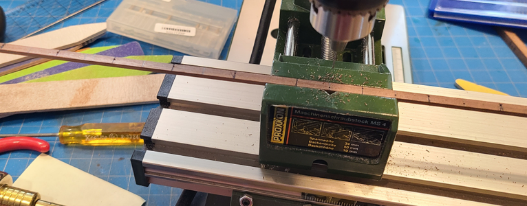
Next, I laid out the bolt locations in the 2x4mm strips to be used. Since I'm not using treenails in the hull (or anywhere, for that matter), I wanted the nails in the strakes to line up with each other. I chose 1/2" spacing (every 30" in the 9" high strakes), staggered top to bottom. I laid out the top nails with ink lines, and bottom ones with pencil, to keep from getting confused:
1683429470728.png

I used a piece of 4x4mm held in the drill press vise with a piece of paper for clearance, placing the 2x4mm strake on top, for consistent distances from the edge:
1683429538133.png

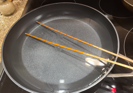
As I mentioned earlier, I used the "soldering iron" heat plank bender, but was having problems bending the 2x4 strakes enough for the bow area. I (somehow) reasoned that boiling the strips in water would make them bend better than the bender would (yeah, I know - hindsight):
1683429623830.png

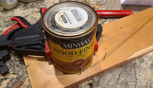
I then jury-rigged a way to bend the strips consistently for use at the bow:
1683429660157.png
Above is shown with a much thinner strip. Who knew Minwax was so versatile?

Well, it didn't work. Both initial strips immediately broke, right about under the "oo" in "Wood Finish". Guess the soldering iron method was better. My future hope is that with a bit more water on the strips, maybe a bit of heat from the bender, and if I go along and nail each strip every 1/2" per the holes, it will work okay. Or at least crack often, at each nail, with small cracks. We'll see.

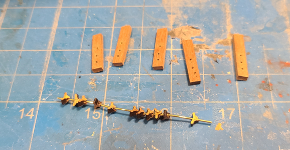
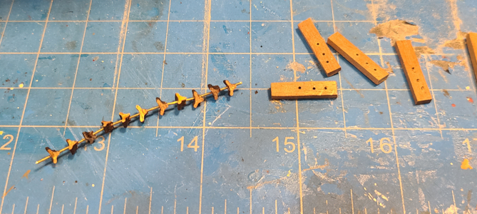
Delaying this task as long as possible (one of my best qualities), I thought I would instead work on the inner details for the rails. This required some cleats, included with the kit with outlines cut, which had to be shaped and placed on wires. How the heck does Olha drill these things so perfectly free hand??? Not me! But I managed to drill a bunch of them, and threaded them on brass wire:
1683429908197.png
The vertical reinforcements in the rails are pre-drilled for the cleats and future gun gun tackles.

I then spaced the cleats out on the wire, gluing them in place with CA glue:
1683430033785.png

After cutting each one loose, I shaped the outer edges of the cleats while holding the brass wire in pliers. After gluing the cleats to the braces, then placing the braces in the model, I have this:
1683430125331.png
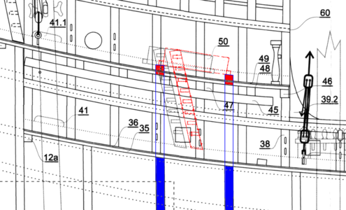
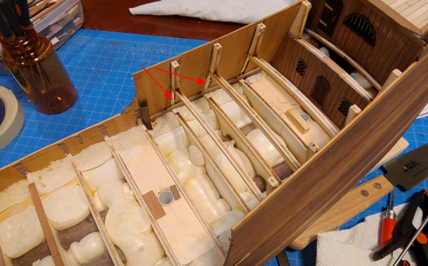
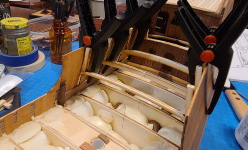
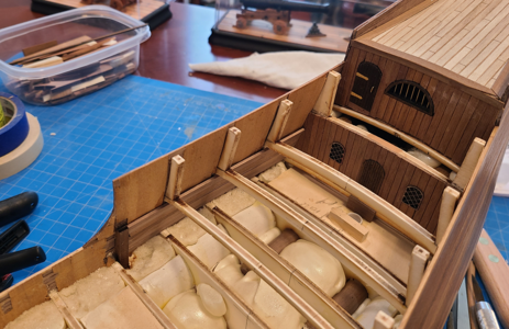
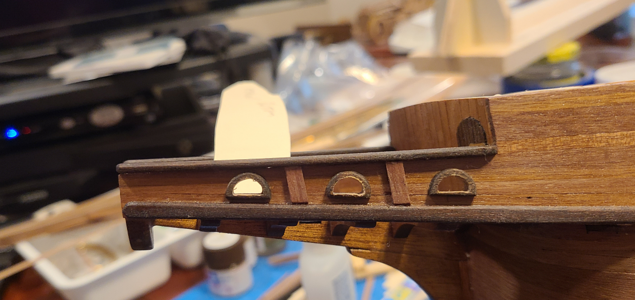
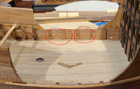
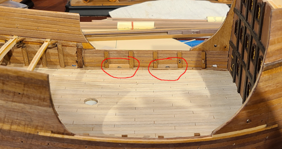
The red circled areas are where Olha cut short pieces, with rectangular holes where drains are located, to finish off the area better. So I made two pieces as a trial to see how doing that might work:
1683430186322.png
The one on the left is 1.5mm thick, while the one on the right is 0.6mm thick. I'm trying to decide if the added strips are worth it, given the time to cut and shape each to fit, as well as put in holes where applicable. They will also prevent the gun carriages from getting as close to the outside, limiting how much of the barrels extend through the gunports.

I'm not sure which way I will go. I'm not relishing all the extra work, but where there is a gap, or sloppy holes, I can correct them. And if I make the added pieces sloppy, they can be scrapped and new ones made. I'll have to sleep on this one. Which is what I'm going to do right now.
 
Last edited:
Back
Top