you are on a very good way - step by step - frame by frame
You are using an out of date browser. It may not display this or other websites correctly.
You should upgrade or use an alternative browser.
You should upgrade or use an alternative browser.
La Salamandre 1752 1:48 (CAF) by Salty
- Thread starter Salty
- Start date
- Watchers 23
-
- Tags
- caf model la salamandre
- Joined
- Mar 1, 2023
- Messages
- 107
- Points
- 213

Fish&Chip, I think “you can play the guitar or build them” is a brilliant expression. Hopefully, we all have a few guitars left in us all before we go.
Thanks to Uwek and everyone else who has visited my diary. Hopefully I can continue to keep you entertained…
The floor timbers frame 11, 12 and 13 are slightly longer than indicated on the plan. This applies to the pieces in both layers in the frame. All in all, it was less than a millimetre. The floor timbers are in two layers. On one layer, the floor timber is one piece (forward facing) and two on the other (aft facing) (see post #5)
On frame 11, I adjusted by sawing a sliver off off each end of the forward facing timber and one end of each aft facing timbers.
On frames 12 and 13, I just sanded the ends as the adjustment was so small.
- Joined
- Mar 1, 2023
- Messages
- 107
- Points
- 213

Work on the frames progresses. I won’t post photos as I am sure you have all seen enough photos of stacks on other logs.
Once or twice, I have had to stop gluing mid frame as I have not been satisfied with the joint between frame components. Even though the ends of each component may be flat, there can be a gap when lining up their sides with the layer below. Fortunately, it’s easy to fix and I would rather do that press on and get a result I want happy with.
I am quite happy with the frames so far. They seem to match the plans quite well. One or two are about five millimetres wider at the top, but some gentle pressure shows they match the plan. I hope that it can be corrected perhaps when the stiffening and longitudinal elements are fitted to the hull. The real test will be bevelling and final finishing the frame for fitting on the keel.
Last edited:
- Joined
- Mar 1, 2023
- Messages
- 107
- Points
- 213

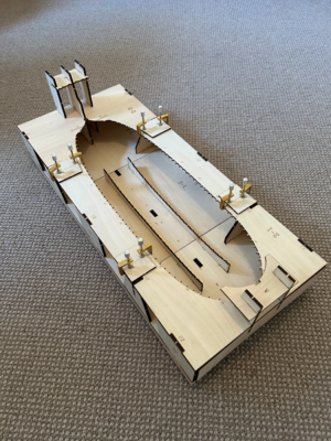
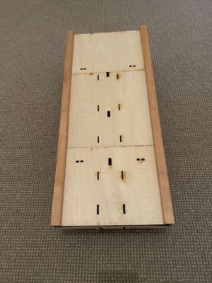
At Uwek’s suggestion, I made a start on the jig so that I can check each frame as I complete it. In addition, the jig is also a safe way to store frames as many are quite delicate, particularly those midships.
Two very minor issues.
The base of the jig is two overlapping layers of plywood. There was a piece missing from the bottom layer which is there for bracing the top layer. A few 2 x 2 cm battens were used instead.
I also had some trouble fitting the middle section which supports the stern. In the end, I had to cut it in half to get it to sit back in line with the two outer sections! The result seems to match the instructions (both for the jig, but also for the stern framing) so I hope it’s right…
If you look closely, you can see markings showing the angle for frame 45 which is a canted frame.


- Joined
- Mar 1, 2023
- Messages
- 107
- Points
- 213

After building the jig, I had a look at the keel (although I don’t think I will actually build it until the frames are finished). One thing I did notice is the decorative insert in the stem:
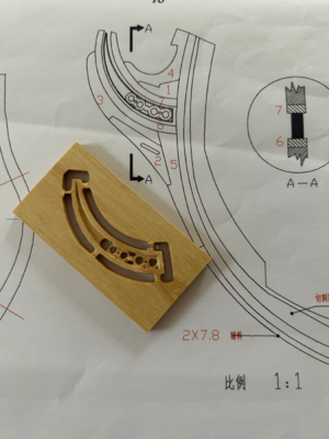
This is a picture from the CAF website:
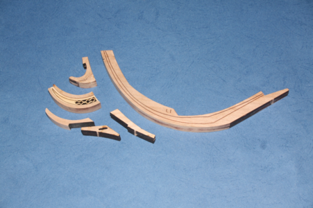
I think I can do some work to better define the four “holes” at the base of insert. They are part of the decoration.
I would appreciate your thoughts about the fifth large hole on the very left which seems like it shouldn’t be there. Some options might be:
One thing to remember is that the Salamander figure head will obscure a lot of detail in the insert but it would still be good to have something well made there.
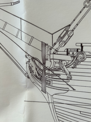
Bourdoit and Bert have a similar diagram.
Below is a picture of an actual model taken from
https://www.modelships.de/Salamandre_Schoeberl/salamandre_II_eng.htm
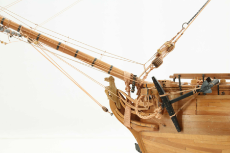
If you have time, I would recommend you have a look at the other pictures of this lovely model.

This is a picture from the CAF website:

I think I can do some work to better define the four “holes” at the base of insert. They are part of the decoration.
I would appreciate your thoughts about the fifth large hole on the very left which seems like it shouldn’t be there. Some options might be:
- patch the hole
- enlarge the hole so it extends to the tip at the left and not fill it in (leaving the framing section around the outside intact, plus the four holes at the base)
- enlarge the hole and then fill it in as (probably) intended (there is plenty of spare material to cut a new piece from)
- remake the entire interior section, including the four holes at the base
- remake the entire interior section with a blank piece with no decoration
One thing to remember is that the Salamander figure head will obscure a lot of detail in the insert but it would still be good to have something well made there.

Bourdoit and Bert have a similar diagram.
Below is a picture of an actual model taken from
https://www.modelships.de/Salamandre_Schoeberl/salamandre_II_eng.htm

If you have time, I would recommend you have a look at the other pictures of this lovely model.
Last edited:
Hi Salty,
I would prefer using some small milling used in PCB board to deburred de holes. But take photo and drwaing in case something goes bad to redo the piece.
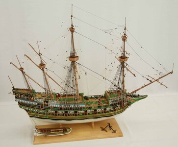
Thanks alos for the link, I found nice pics for my next build : the bounty. Thi will be helpful. SOme really nice galeon from aroud 1610 too.
Have a good day,
Michel

- Joined
- Mar 1, 2023
- Messages
- 107
- Points
- 213

Thanks to everyone who has visited by diary and left messages of support and encouragement. Much appreciated.
Michel, thanks for your suggestions. I will think a bit more about the best way to tackle the problem but I will need to do something sooner rather than later as it is part of the keel which is next on the list after the frames.
I have reached frame 20 and no bevelling is required.
Progress is not spectacular, but steady with one frame most days during the week and sometimes 2 per day on the weekends (glue up morning and night). I don’t have enough clamps to go faster even if I wanted.
Sorry for the lack of excitement.
Last edited:
- Joined
- Mar 1, 2023
- Messages
- 107
- Points
- 213

Frame 23 seems to be the reverse of frames up 22 with the layer with one floor timber now facing aft. Prior to the it always faced forward (see post #5).
Bevelling starts again on frame 25. I think the numbered layer faces forward, but the edges to bevelled reverse - forward layer now has the inside bevel and aft layer has the outside bevel.
Bevelling starts again on frame 25. I think the numbered layer faces forward, but the edges to bevelled reverse - forward layer now has the inside bevel and aft layer has the outside bevel.
- Joined
- Mar 1, 2023
- Messages
- 107
- Points
- 213

Thanks to everyone who has visited my diary in the last week.
I have been away for a few days for Easter…
Taking a break from gluing frames, I have been working on finishing some frames which won’t need to be bevelled.
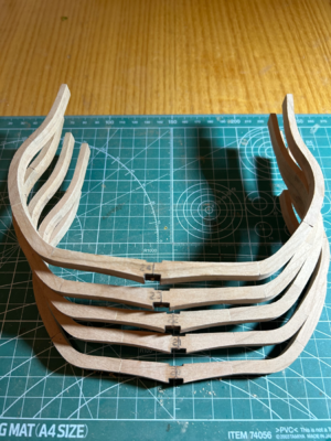
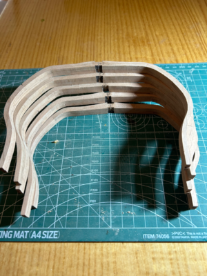
I am just doing this work by hand. I start with a razor blade to remove most of the charred surface from the laser on the outside and inside, then use a sanding pen with 120 grit and finish with 320 grit. I shall probably use a finer grit later but the finish seems OK for now. I find a bit of care is needed especially with the coarser grit as it can do damage quickly - either leave gouges or round the edges. I am trying to remove a bare minimum of material and thankfully that is easy to judge given the colour difference between the charred surface and the wood underneath.
The photos are a little unflattering if enlarged, but I am pleased with the results - as mentioned in post #8, the American cherry works to a very fine finish.
Although a lot slower, I am happy doing everything by hand for now. Quite therapeutic and restful compared to my day work.
A few joins in the frames are more visible than perhaps I would like, but I will leave them as they are for now. I know that it is likely that most of the frames on the starboard side will be covered in planks (internally and externally). On the port side, a lot of futtocks may eventually be removed to show the inner structure and the top of the frames will be obscured by the wales (as can be seen in this photo from the CAF website):
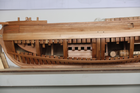
I think that the main issue the gap itself (when the glue doesn’t quite fill the joint) and a small amount of glue (even if it does not completely fill it) might go a long way to fixing the problem.
If I do a good job on the frames, at least I will have choices later on…
I have been away for a few days for Easter…
Taking a break from gluing frames, I have been working on finishing some frames which won’t need to be bevelled.


I am just doing this work by hand. I start with a razor blade to remove most of the charred surface from the laser on the outside and inside, then use a sanding pen with 120 grit and finish with 320 grit. I shall probably use a finer grit later but the finish seems OK for now. I find a bit of care is needed especially with the coarser grit as it can do damage quickly - either leave gouges or round the edges. I am trying to remove a bare minimum of material and thankfully that is easy to judge given the colour difference between the charred surface and the wood underneath.
The photos are a little unflattering if enlarged, but I am pleased with the results - as mentioned in post #8, the American cherry works to a very fine finish.
Although a lot slower, I am happy doing everything by hand for now. Quite therapeutic and restful compared to my day work.
A few joins in the frames are more visible than perhaps I would like, but I will leave them as they are for now. I know that it is likely that most of the frames on the starboard side will be covered in planks (internally and externally). On the port side, a lot of futtocks may eventually be removed to show the inner structure and the top of the frames will be obscured by the wales (as can be seen in this photo from the CAF website):

I think that the main issue the gap itself (when the glue doesn’t quite fill the joint) and a small amount of glue (even if it does not completely fill it) might go a long way to fixing the problem.
If I do a good job on the frames, at least I will have choices later on…
Last edited:
- Joined
- Mar 1, 2023
- Messages
- 107
- Points
- 213

After the excitement in the last post, it is back to frames
On frame 26, I checked the pieces against the plan as usual:
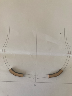
Both are pieces approximately 2.5 mm (3/32 of an inch) longer than indicated on the plan.
I though I might have accidentally mixed up the pieces with those in other frames. I checked frame 25, which had been glued and it matched the plan, and the pieces for frame 27 which have not been glued and they also matched the plan.
So I reluctantly trimmed the outer ends (the component wouldn’t match the plan if the inner ends were trimmed) with a saw.
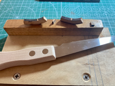
Everything glued up well and the frame matched the plan, but it is a bit mysterious that these two pieces were too big.
On frame 26, I checked the pieces against the plan as usual:

Both are pieces approximately 2.5 mm (3/32 of an inch) longer than indicated on the plan.
I though I might have accidentally mixed up the pieces with those in other frames. I checked frame 25, which had been glued and it matched the plan, and the pieces for frame 27 which have not been glued and they also matched the plan.
So I reluctantly trimmed the outer ends (the component wouldn’t match the plan if the inner ends were trimmed) with a saw.

Everything glued up well and the frame matched the plan, but it is a bit mysterious that these two pieces were too big.
Think about to buy a disk-sander - it will work much faster and more accurate (90° degree angle) than cutting with a handsaw.
Take a short look at my building log of my Salamandre - this post and the following
These parts / elements of the frames are on purpose slightly too long. The reason is, that every modeler is working in a different way to remove the laser char at the butt joints of the elements - there is the possibility, that some modelers would sand away to much, so that they would be too short.
Therefore CAF prepared them slightly too long
Take a short look at my building log of my Salamandre - this post and the following
LA SALAMANDRE, bomb ketch - POF - (CAF-models, 1/48)
Due to the fact, that I am waiting for the spar jig, which will be hopefully send by Max in short time, I started with some frame work. As I mentioned before the Salamandre is the first laser cut POF model, so I have to get used to the small but important specialities of this kind of wood /...
shipsofscale.com
These parts / elements of the frames are on purpose slightly too long. The reason is, that every modeler is working in a different way to remove the laser char at the butt joints of the elements - there is the possibility, that some modelers would sand away to much, so that they would be too short.
Therefore CAF prepared them slightly too long
I see you're making good progress, great and clean frames, keep it up.
- Joined
- Mar 1, 2023
- Messages
- 107
- Points
- 213

Uwek, thanks for the explanation about the reason for variations in the size of frame components. I agree that a sanding machine would be nice and will put it on my shopping list.
Tobias, I have been building frames for about five weeks now. Everything seem to be going well, but I realise that all this is just preparation for the real building work. I hope my ship will be half as good as your Le Coureur and La Palme.
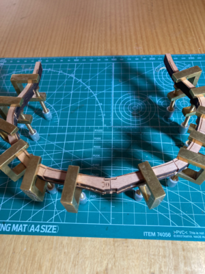
On frame 30, the floor timbers in one layer was narrower than the other. A quick check of the plan showed a better fit if everything was aligned to the inner frame:

- Joined
- Mar 1, 2023
- Messages
- 107
- Points
- 213

Just a short update:
I had a bit of a wrestle getting the pieces for frames 31 and 32 from the billet. Usually they come away freely after cutting a few tabs holding them in place, but the laser hadn’t quite cut as deep as it normally does on this sheet.
Frame 32 has 17 pieces, whereas frame 31 has 15 pieces.
From frame 36 onwards, the floor timbers are noticeably wider going aft compared to those midship. This seems to be because the amount of bevelling required is increasing as the hull is tapering.
- Joined
- Mar 1, 2023
- Messages
- 107
- Points
- 213

Still more frames…
Thanks to everyone for your continued interest. Hopefully, I can show you something different in the near future.
You might have noticed that I have recently changed the picture under my username. It’s my “other” boat, Peggy, a Herreshoff 23 daysailer. She is built of wood using traditional boat building methods and is gaff rigged. She was launched in 2014.
- Joined
- Mar 1, 2023
- Messages
- 107
- Points
- 213

Thanks for sticking with me - it seems like I have been at this for a while.
I am nearing the end of the regular frames before starting the stern frames. I made three frames on the weekend and two today as it is ANZAC day, public holiday in Australia.
I am nearing the end of the regular frames before starting the stern frames. I made three frames on the weekend and two today as it is ANZAC day, public holiday in Australia.
step by step and frame by frame - that is one part of POF-game
But the time will come, when you have all frames installed and the hull is out of the jig
But the time will come, when you have all frames installed and the hull is out of the jig
Hi Salty, thanks for the kind words. Uwe is absolutely right, when all the frames are built it will be a great result and you can be proud of it. At La Palme it took almost 7 months.Uwek, thanks for the explanation about the reason for variations in the size of frame components. I agree that a sanding machine would be nice and will put it on my shopping list.
Tobias, I have been building frames for about five weeks now. Everything seem to be going well, but I realise that all this is just preparation for the real building work. I hope my ship will be half as good as your Le Coureur and La Palme.
On frame 30, the floor timbers in one layer was narrower than the other. A quick check of the plan showed a better fit if everything was aligned to the inner frame:
View attachment 369595
- Joined
- Mar 1, 2023
- Messages
- 107
- Points
- 213

I am about to start working on frames 44 and 45 which are a little different to the others.
Bourdiot an Berti show this
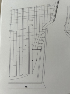
The CAF plans show something a little different
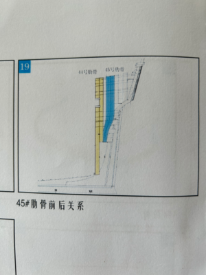
In the CAF plan, the forward half of frame 45 doesn’t protrude and replace part of the aft half of frame 44.
I will stick with CAF rather than try to adapt the kit to Bourdoit and Berti.
Bourdiot an Berti show this

The CAF plans show something a little different

In the CAF plan, the forward half of frame 45 doesn’t protrude and replace part of the aft half of frame 44.
I will stick with CAF rather than try to adapt the kit to Bourdoit and Berti.
Hello salty, in that case I would stick with the CAF plans. The risk that something will not fit later is too great.


