Yes, I didn't paint it I liked the natural colour, and imagined it similar to my old unfinished basement with unpainted wood framing.Carl, it looks like you left the inside walls of the engine room unpainted. Is that correct? Did you stain them at all?
You are using an out of date browser. It may not display this or other websites correctly.
You should upgrade or use an alternative browser.
You should upgrade or use an alternative browser.
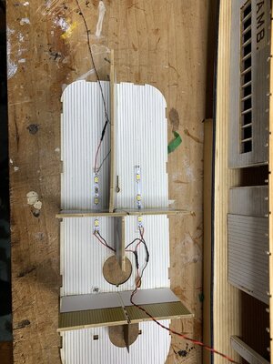
I finished wiring the main cabin, with the exception of the front parlour. For the parlour, the lights are installed from above and the LEDs shine through holes in the ceiling. I will do this lighting, which also includes the wheelhouse and captain's quarters once the main cabin roof is completely assembled and fixed to the engine room roof.
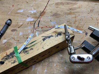
There are 2 light strips that provide the lighting for most of the main cabin. I have never done much soldering before, apart from attaching brass wires to each other, so all this fine wiring and soldering was a challenge. I spent about a day practicing on scrap, etc. but even then attaching the + and - wires to tiny terminals on the light strips was a bit daunting. But I made it through. Another modeler who has done LED lighting for years coached me and provided great advice.
On the lighting side, the instructions recommend a 12V DC connection and assumed that the model will be powered from an outlet. However, my model will be displayed on a shelf and far from any outlet, so I have chosen to use a 9V battery holder with a push-button on-off switch. There will be a bunch of wires coming out of the bottom of the hull, and they will be hidden in a compartment that I will make on the base for the model.
I decided to fix all the wires and lights before adding the walls. That way I had easy access and could better manage things. Note that when you are adding the inside walls, you are installing them upside down. The ceiling/roof is flat on the workbench and you are building from the top-down, not bottom up.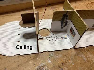


- Joined
- Dec 31, 2017
- Messages
- 228
- Points
- 133

Thanks. I’ll just put some Cherry Danish Oil on to bring out the grain.Yes, I didn't paint it I liked the natural colour, and imagined it similar to my old unfinished basement with unpainted wood framing.
That should work well. By the way, I painted the engine room ceiling a light grey colour. The colour of the ceiling piece was too dark for my taste, and I wanted to keep the room from looking too dark. Even though there is LED lighting, I wanted everything - the boiler, pipes, machinery, etc. to be easily visible.Thanks. I’ll just put some Cherry Danish Oil on to bring out the grain.
The continued progress on the boat. Yesterday and today I built more elements of the main cabin. This includes a parlour room with 2 divans, or settees. There are 2 of them, and you have to build them in the correct orientation of the various pieces. What I didn't realize, until too late, was that these divans, which are curved to fit an inside wall 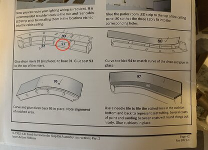
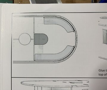
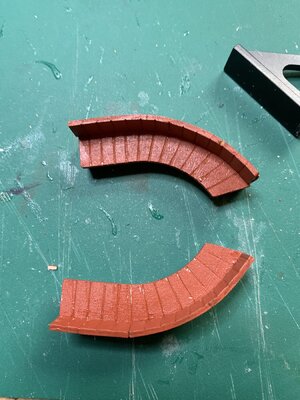
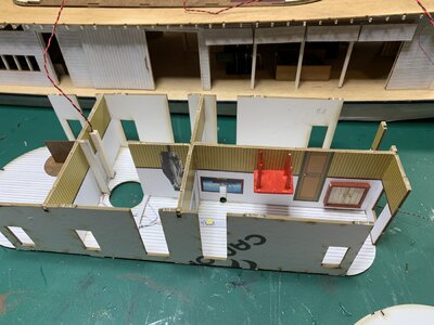 . One is shorter than the other to make room for a door. As it turned out my longer one would only fit on the door side, hence blocking the door. So, I needed to cut it to size. This was not difficult. I could then place them properly. So when you get to this step, be careful to orient the pieces in front of you so that you build them to fit the diagram (attached).
Another thing with respect to the divans. The instructions describe part 91, as being part of the assembly. I looked high and low and couldn't find this part. So don't go looking. It doesn't exist!! This is an error in the instructions. The part in question that you will need is part 92, along with the others.
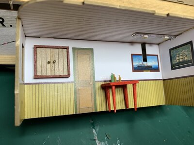
I also added a few of my own items to the main cabin, including a small table and a cupboard. I also scribed the ceiling, and painted it white to make it more realistic. probably shouldn't have bothered. The windows are so small, that you would probably have to stick your eye right up to it to look inside, and you wouldn't get much of a view!!


Thanks Tomazona. I appreciate your positive comments!Carl… I am very impressed with the level of detail on the boat and your additions look beautiful. I look forward to seeing your progress.
- Joined
- Jul 26, 2013
- Messages
- 380
- Points
- 158

Looking nice! I use 9v batteries for powering 12v LED bicycle lighting all the time and the batteries last for years.
- Joined
- Dec 31, 2017
- Messages
- 228
- Points
- 133

Carl, it looks like you added a whole lot of piping to the engine room (like the piping going from the boiler to the engines) that are not in the instructions, as well as what look like engine controls, storage boxes, etc. Where did you get those designs from, especially the additional connections from the boiler to the enginesL Seems like they would have been on the actual ship. Don’t know why they weren’t included in the instructions or am I missing something?The engine room still looked too empty, so I added a few additional extras, including some oil barrels and a housing for the steering mechanism. There's still room for more cargo, so additional items might be added. The walls on the main deck are now up and soon I will begin working on the next level. So far I have been impressed with how well the parts fit together.View attachment 386682View attachment 386683
View attachment 386684
View attachment 386685
View attachment 386686
Yes, the piping wasn't included. I wrote to the builder. Here is his response:Carl, it looks like you added a whole lot of piping to the engine room (like the piping going from the boiler to the engines) that are not in the instructions, as well as what look like engine controls, storage boxes, etc. Where did you get those designs from, especially the additional connections from the boiler to the enginesL Seems like they would have been on the actual ship. Don’t know why they weren’t included in the instructions or am I missing something?
Hi Carl,
Regarding the steam pipes, I have pretty much left that up to the modeler as we had to stop on the detail somewhere as I could have gone nuts with the interior detail and made it a very complicated kit, so we opted to simplify a bit.
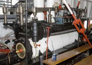
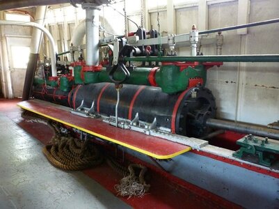
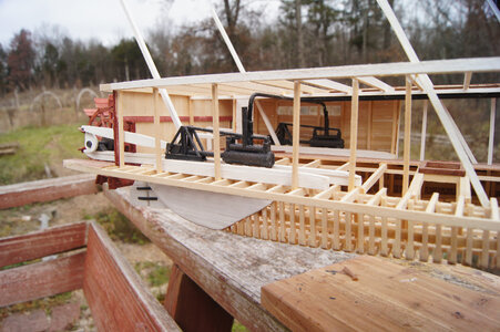
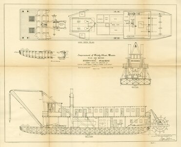
This forum thread should give you some ideas on adding interior details that would be typical to this sort of build. Not the same ship, but similar requirements all the same.
https://www.finescalerr.com/smf/index.php?topic=3143.15
The attached random pictures show some ideas on the piping and engine colors. Typically there would be one pipe running from the boiler overhead and then split to both engines. The other engine pipe would exhaust to atmosphere either directed out the aft or sometimes close to the waterline.
The pipe would exit the middle top of the boiler and go to the engines.
Hope this helps to get you started.
Cheers!
Darryl
Hi, me again. It seems as though Darryl's photos got mixed up a bit with my text.
The steam pipes were made from 1.5 mm brass, painted black.
As for the other things I added, I basically winged it based on what I had seen before or on other photos. I made the woodbox from bits of scrap, and used twigs for the firewood. Since lighting would have been introduced around 1890-1900 , I added a steam-powered generator based on a bit of google research. I also added some additional controls near to engines which would have allowed for forward and reverse controls. And a bunch of other little things - storage barrels (made from dowel). By the way, much of the detail, especially aft, is almost impossible to see once the walls go up!!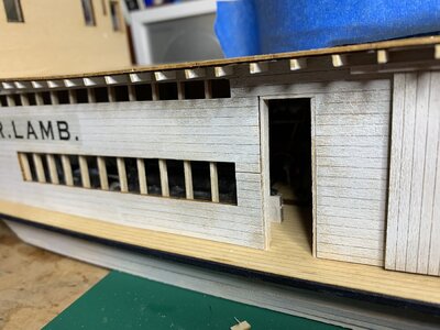

I'm glad you are enjoying the progress. No, none of the doors are hinged, so you can't open and close them. If you mean the doors that fold vertically, thhow open en these are also fixed, since the hinges are just decorative. You can decide when you are building the model how open or closed they should be.Carl... I am enjoying watching your progress. Thanks for sharing.
Are the side door actually hinged? Can you open them up like in the real boat?
I like the final appearance of your walls - with this very light washed look - very authentic and realistic
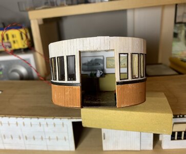
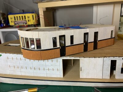
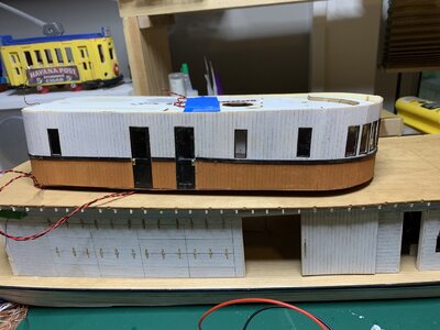
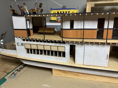
Did some more work on the main cabin. I finished adding some furniture, installed the windows and doors and put on the external skin - thin pre-scribed wood panels that are cut to fit exactly the contours of the cabin respecting all the openings. It is a very precise fit. You have to be careful when applying it around the curvatures. While it bends easily, it can split along a scribed mark. This happened to me. While it was easy to join the pieces together, the break created a more visible crack. To close it so that it would be totally seamless means that a very small trimming would be necessary. The downside is that even a tiny bit of trimming would shorten the piece at the other end. Since the fit is absolutely exact, you would now have to fit a very tiny, narrow sliver at the other end to compensate. So, I didn't bother. If you look very closely you might see a very slight gap between the "boards" where the split took place. This is a long-winded way of saying be careful when bending the pieces so that they don't crack or split. If I was to do this again, I would soak the pieces that need curving.
I then painted the cabin and added a decorative border. I am almost ready to start the LED light installation for the next deck up.
Again, lots of fine detail. Take a look at the size of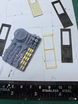

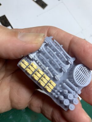
 3D set of door knob fixtures (painted brass).
I then painted the cabin and added a decorative border. I am almost ready to start the LED light installation for the next deck up.
Again, lots of fine detail. Take a look at the size of


 3D set of door knob fixtures (painted brass).
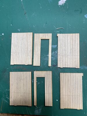
The next part of the build was putting together the toilets which are located aft of the main cabin. The instructions do not any treatment of the rear wall between the toilets. I decided to make the wall a match with the toilets, but using very narrow and thin strips from a previous project to try and match the etched toilet walls that come with the kit. To make it easier to install I built the wall on a cardboard template which I glued to the back wall once the strips were glued and painted.
I also completed the wiring. All the LEDs -12 ofd them - are wired up. I still have to thread them to their final locations and insert them in the various fixtures. There is quite bit of slack, but fortunately there is a space between the decks where I can tuck in the excess wiring.
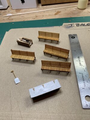
I also think that the engine room is still looking a bit empty so I build a firewood box, a storage box and another shovel. I also put together the benches that will eventually go on the cabin deck.
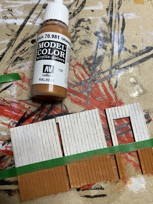
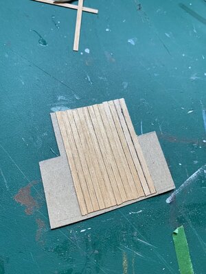
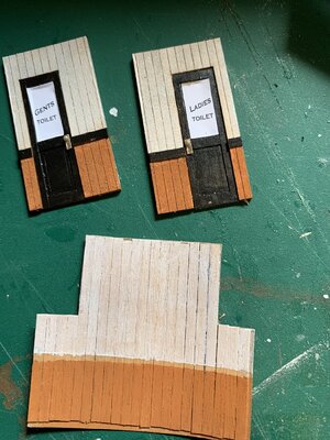
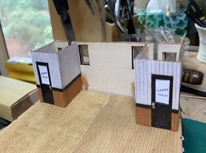
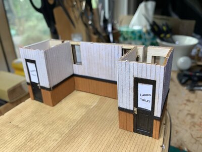
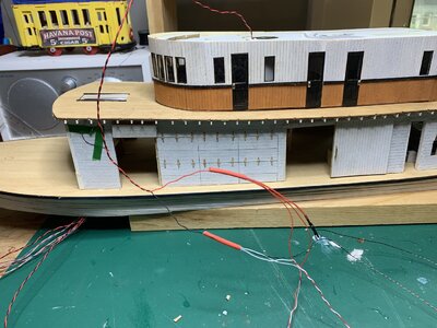
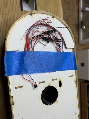


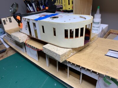
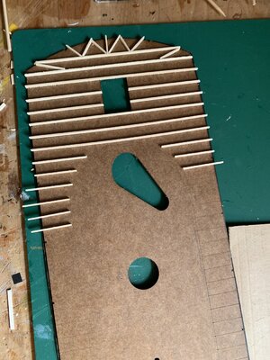
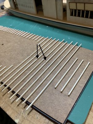
Now that all the wires are in, I glued the main cabin onto the engine room roof and worked on the next deck. This is similar to the engine room roof, with 2 x 4 ceiling rafters. As with the previous roof, I had to be careful to arrange the rafters so that they will be flush to the exterior cabin walls. There are scribe marks on the roof to mark the locations of the rafters which makes this job quite easy. Since an LED light will exit the rear of the cabin to light up the outside deck, I cut out a narrow channel through the rafters, for the LED wire. (see photo with arrows marking the channel.)
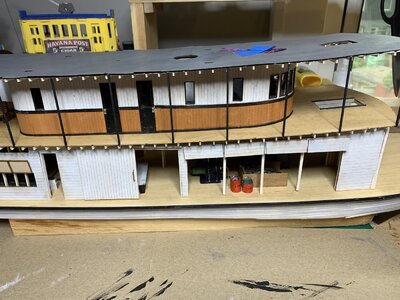
The top of the deck is covered with tar paper. In the kit, this is a thick black paper stock. As recommended, I painted this with a dark grey to simulate fading. The kit instructions also recommend using a make-up sponge and masks to dab more paint to lighten up the middles of the paper segments. I didn't follow this instruction, I was just too afraid that my dabbing and masking would create a bit of a mess, so I just painted it the uniform dark grey. Also, there is a lot to add to this deck- captain's quarters, lifeboats, wheelhouse, funnel, etc. so I'm not sure that the extra fading would be all that noticeable.


The top of the deck is covered with tar paper. In the kit, this is a thick black paper stock. As recommended, I painted this with a dark grey to simulate fading. The kit instructions also recommend using a make-up sponge and masks to dab more paint to lighten up the middles of the paper segments. I didn't follow this instruction, I was just too afraid that my dabbing and masking would create a bit of a mess, so I just painted it the uniform dark grey. Also, there is a lot to add to this deck- captain's quarters, lifeboats, wheelhouse, funnel, etc. so I'm not sure that the extra fading would be all that noticeable.
Time to add the railings to the passenger deck. There are 3 parallel railing, with a separation of 0.25" between them. (This kit's measurements are in Imperial - not metric). I was trying to figure out a way of marking the separations- maybe making the stanchions with pencil, or creating some sort of spacer. Then I realized that I had a roll of masking tape that was the exact width - .25". So, I just taped this on and glued on the horizontal rails just above the line of the tape. Easy! 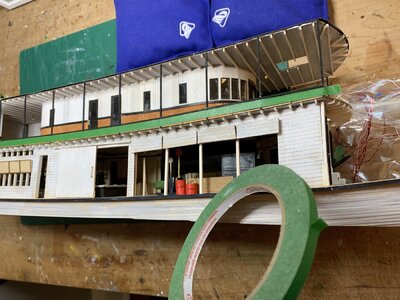
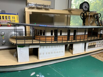


She is getting impressive, Carl.Time to add the railings to the passenger deck. There are 3 parallel railing, with a separation of 0.25" between them. (This kit's measurements are in Imperial - not metric). I was trying to figure out a way of marking the separations- maybe making the stanchions with pencil, or creating some sort of spacer. Then I realized that I had a roll of masking tape that was the exact width - .25". So, I just taped this on and glued on the horizontal rails just above the line of the tape. Easy! View attachment 392125View attachment 392126
Regard, Peter


