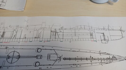
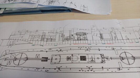
Help! Plans/Details needed for AVANT GUARDE class boats

Today I tryed out my luck dear friends to it's very end and got totally broken!
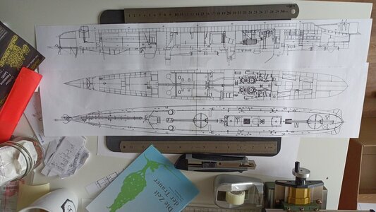
IMG_20231217_122245_379.jpg
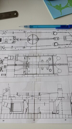
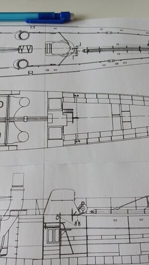
I did work with my overhang of 1/72 copies to get some idea about the mistakes towards the stern end of the drawing's side view. Due to this the sideview was cut out and I added the CWL onto it and placed it below the CWL cut top view to get the inner structures alined:
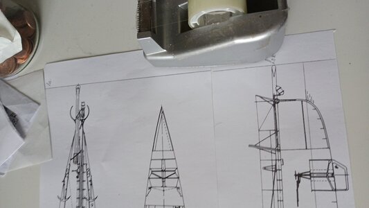
IMG_20231217_123912_466.jpg

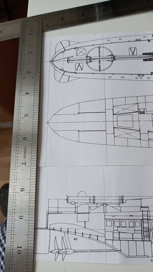
Above: Alineing the tip of the boat at the "ram spear" made clear that the stem is alright - no disturbing mismatch no annoying error in here
'urra!*
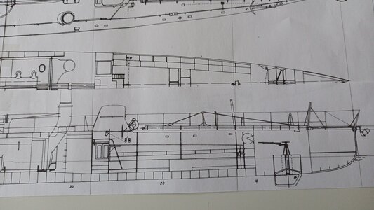
IMG_20231217_124951_872.jpg
My next point of measurement was the front conning tower's aft end. Working quite well in a tolerable way.
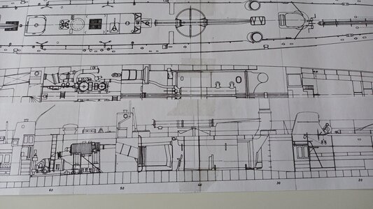
IMG_20231217_124938_965.jpg
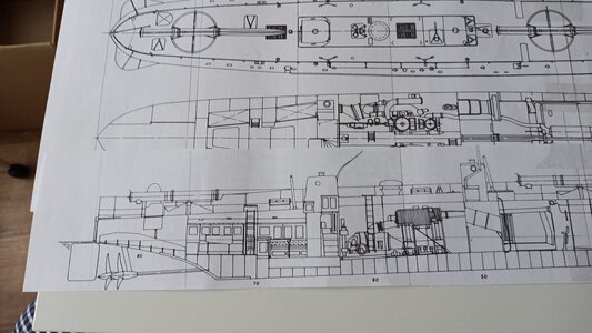
But the very next point was the pivoting point of the fore TorpedoTubev- and at this the mismatching gets to an unbeliveble gap! Look at the mushroom vent! By this it is clear beyond bulkhead 50 it is getting worse and worse:
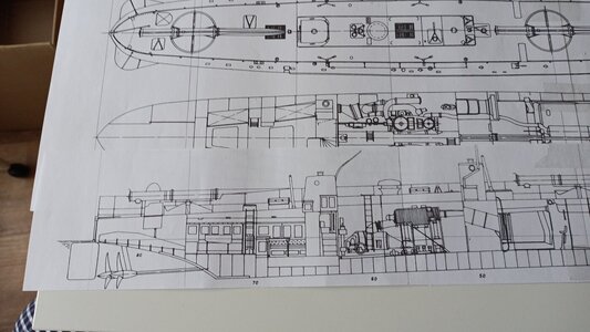
IMG_20231217_124927_023.jpg
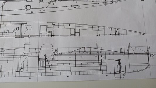
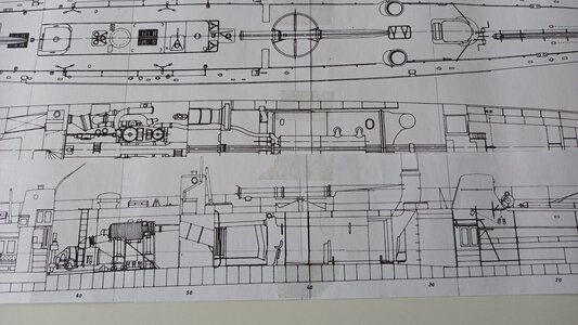
And the more we do come towards the very stern the more mismatching we do have to suffer...
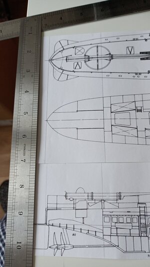
IMG_20231217_124000_644.jpg
It does look like the aft part was pictured in an lateral Angle so it does get shorter and shorter the more to the stem we do come.

@Ab Hoving My humble question to the specialist:
So I should stay with my solution to lengthen only the last bulkheads above the propellers? Or should I insert a number smaller "spacers" of 0,5 mm (~0.01968" ) behind (in a regular distance) bulkhead for example at N°40, 50, 60, &c. to get a more tender correcture over the length of the stern part of the side view? What would be your advice to me?

Thanks you very much and have a great III.Adent's sunday.

______
*as the French do pronounce it in a very Russian way ;-)
 
Last edited:
Hi Christian. Found your interesting build with ‘old fashion’ drawings.
Regards, Peter
Dear Peter, they are not only oldfashioned - they do need to fit a bigger reshape :rolleyes:.
But being clever I c/would have choosen a better documented boat with aa finescale Set of plans. But I have had fallen in love to her as she shows the transition from spear to fish-torpedo in a single boat...
...beside her lines Okay
 
As far as I can see in your latest pictures only the one on the bottom is slightly short. Do you have access to a design program which is able to 'stretch' that one a bit? There seems to be a scale problem. I would never choose a method that brings ugly dents and bumps into the design.
 
Oggi ho tentato la fortuna, cari amici, fino alla fine e mi sono completamente rotto!
View attachment 414519
Ho lavorato con la mia sporgenza di copie 1/72 per avere un'idea degli errori verso l'estremità poppiera della vista laterale del disegno. Per questo motivo la vista laterale è stata ritagliata e ho aggiunto il CWL su di essa e l'ho posizionata sotto la vista dall'alto tagliata del CWL per allineare le strutture interne:
View attachment 414518

Sopra: allineando la punta della barca alla "lancia dell'ariete" è chiaro che la prua è a posto - nessuna discordanza fastidiosa, nessun errore fastidioso qui
'urrà!*

View attachment 414517
Il mio successivo punto di misurazione era l'estremità poppiera della torre di comando anteriore. Funziona abbastanza bene in modo tollerabile.

View attachment 414516
Ma il punto successivo è stato il perno del TorpedoTubev anteriore - e in questo momento il disadattamento raggiunge un divario incredibile! Guarda lo sfiato dei funghi! Da questo è chiaro che oltre la paratia 50 la situazione sta peggiorando sempre di più:

View attachment 414515
E più andiamo verso la poppa, più disadattamento dobbiamo soffrire...
View attachment 414514
Sembra che la parte di poppa sia stata raffigurata in un angolo laterale, quindi diventa sempre più corta man mano che ci avviciniamo alla prua.

@Ab Hoving La mia umile domanda allo specialista:
Quindi dovrei restare con la mia soluzione di allungare solo le ultime paratie sopra le eliche? Oppure dovrei inserire un numero di "distanziatori" più piccoli di 0,5 mm (~0.01968" ) dietro (a distanza regolare) la paratia, ad esempio ai N°40, 50, 60, ecc. per ottenere una correzione più morbida sulla lunghezza della parte poppiera della vista laterale?Che cosa mi consiglieresti?

Grazie mille e buona domenica III.Adent.

______
* dato che i francesi lo pronunciano in un modo molto russo ;-)
Ciao, questo tipo di dettaglio può aiutarti? Per favore mi faccia sapere.
 

Attachments

  • 5555555.pdf
    5.4 MB · Views: 10
As far as I can see in your latest pictures only the one on the bottom is slightly short. Do you have access to a design program which is able to 'stretch' that one a bit? There seems to be a scale problem. I would never choose a method that brings ugly dents and bumps into the design.
Dear Ab, I am very happy to see your answer - the shipyard is still analog without CADprogramming.

To avoid dents and bumps I decided to put in some strips of paper into the construction in 1/64 to stretch the hull inna smooth way. So there are 12mms (nearly 1/2") of offset WE have to deal with:
IMG_20231218_103748_926.jpg

So I had to analyse where to place these prolonging brackets. I placed the CWL cut directly to the sideview and did draw position lines in to figure out where this awful offset is located:
IMG_20231217_124951_872.jpg
From the stem untill the foreward conning tower everything looks in order (above) - but the drama does strike in more after:
IMG_20231217_124927_023.jpg


IMG_20231217_123946_747.jpg
Due to this the desaster is going to begin afterwards:
IMG_20231217_123936_013.jpg
So upwards we do see clearly how much offset is to be repaired in here 2mms so we do have got 10mms to share!

Again the fore CT does fit!
IMG_20231217_123924_453.jpg
Here the lines do look tricky well positioned- Look at the gigantic mushroom vent:
IMG_20231217_124938_965.jpg
But in the very end the misalinement is obviously there:
IMG_20231217_124000_644.jpg

So I do have to do a serious job to figure out where to place the "spacers" to fit in the 12mms over the after part of the hull AND avoiding annoying bumps and ugly dents. For god's sake I did order a sewing curved ruler so I am able to redrawn the hull's outlines.

So next stop is the fine and detailled diagnosis of the exact location of the shrinking of the hull in detail.

Sadly that's all from me and here.
 
Ciao, questo tipo di dettaglio può aiutarti? Per favore mi faccia sapere.
Frank, thank you very much - being an aviso-torpilleur it isban other type of boat but offering a plenty of interesting details to me. So giving me a lot of answers I wasn't even able to ask so long! You did overtook me - thank you very very much for this enlighting document.
 
Frank, grazie mille: essendo un aviso-torpilleur è vietato qualsiasi altro tipo di barca ma mi offre molti dettagli interessanti. Quindi dandomi un sacco di risposte che non sono riuscito nemmeno a chiedere così a lungo! Mi hai superato: grazie mille per questo documento illuminante.
Ho l'intero progetto,Frank
 
Last edited:
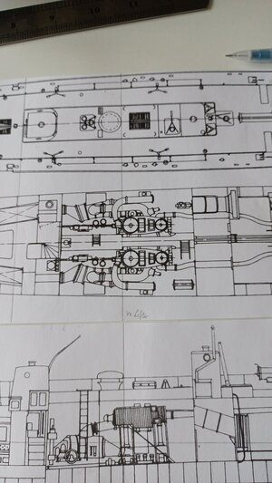
Today I dealt a bit with AVANT-GARDE and figured out The sources of troubles in my original drawings. The distances between the bulkheads is regulary 6-3/4mms BUT there are some longer.
IMG_20240117_134755_915.jpg
Here shown in green and some shorter shown

IMG_20240117_134814_113.jpg
in red step by step in particular below the engine.

So I have to work out what is wrong and where to add my missing millimeteres into the sideview - that is going to be a struggle.
 
Back
Top