CAF HMS Granado 1:48 POF

Have been continuing to work on the mortar ammo storage racks. Wanted to make the interiors visible to highlight the details of the kit. Per the instructions, the racks have both sides fully boarded up, doors on one end and an enclosed opposite end. Only way to see in is through the top. I decided to cut holes in the boarding on the sides and the enclosed end. Below is a photo of how it looks on the bench
DSCF1118.JPG
I also wanted to show what was under the deck inside the ammo lockers so I cut small windows in the deck planks there so you can see clear to the hull
DSCF1115.JPG
Here is how it looked as they were going in
DSCF1114.JPG
DSCF1120.JPG
DSCF1123.JPG
Here is how they look when fully installed
DSCF1119.JPG
DSCF1122.JPG
DSCF1124.JPG

The next steps involve building up structures in the bow and the special purpose templates that are provided in the kit come back into play.
Cheers
 

Attachments

  • DSCF1116.JPG
    DSCF1116.JPG
    304.1 KB · Views: 17
  • DSCF1117.JPG
    DSCF1117.JPG
    279.5 KB · Views: 17
  • DSCF1121.JPG
    DSCF1121.JPG
    299.1 KB · Views: 15
Thank you. The caulking in the keel and ribs was done with graphite powder and white glue. On the planking I just used a black permanent marker run along the edges.
How do you get graphite powder? with a pencil?
Do you have a picture of the process? just by grinding the mine?
On this site, folks have discussed a variety of ways to get graphite powder, one being just grinding down a pencil on a piece of sandpaper. I have found it easier and a lot neater, that powder gets everywhere, to use some pre-ground stuff. The photo shows what I used, avail on Amazon and in craft shops
IMG_0388.JPG
Hope this helps
 
Oh my Goodness - unbelievable - beautiful.
 
Very good progress, and "looking good progress"
You are faster than me with only the section - great work
 
All, have discovered that I have a problem with my build, fairly significant, have emailed Tom to see how much trouble I am in. In a nutshell, my athwartship rib sets and the corresponding mortar round racks are more than 1cm further aft than they should be. Not possible to remove and relocate at this point without extensive kit damage. Wanted to get this out to other Granado builders before they got into the same predicament. Have tried to do some forensic analysis to determine what I got wrong, here is what I found:
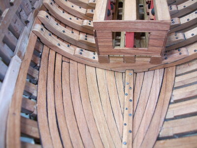
First, this issue came to my attention as I started to fit the template for the lower level bow decking into the kit
DSCF1130.JPG
You can see in the above photo that my template is too short for the space that exists. The kit provides extra planking to make this deck section so this is not a big issue. Why I have too much space is the issue.
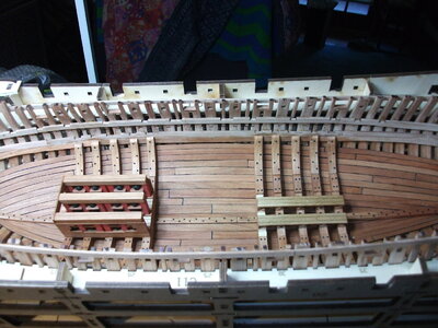
The piece that I think is at issue is 3B-B1 which is the lower thick plank that is installed to firm up the ribs.
DSCF1129.JPG

3B-B1 goes from the stem aft, and is roughly 120mm long as it comes out of the provided sheet. When that piece is installed, the butt lands on frame 11, that is where my piece fit. I made the assumption (with all the bad things that entails) that the next piece of thick plank that is installed, 3A-B2, butts up to the end of 3B-B1. I did not check that on the plans before I proceeded, my mistake. You can see in the below picture how it should go and how mine went.
DSCF1132.JPG
DSCF1128.JPG
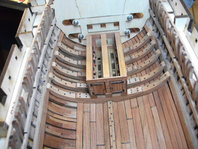
In the above photo, I have circled the joint in question. In hindsight, I should have shortened 3B-B1 before installing so that the butt landed on frame #10. The next plank piece moving aft, 3A-B2, has all the notches that define where the athwartships ribs and, thus, the mortar round racks, are located. Not having the third section of the kit in hand yet (estimated March release) I can't tell how bad this will get. Hope to get some insight from Tom shortly. In any event, will do what ship modelers do which is adapt and overcome.
Cheers and better luck to you other builders.

DSCF1131.JPG
 
I am sure, that Tom will try everything and check the possibilities and the future adjustments
Many Thanks for sharing this, so other can have this in mind when doing their model. :cool:
 
Ouch!
Many thanks for letting us know there may be a problem. With your skills I'm sure you will get over it.
As I posted earlier in my build, it's easy to make mistakes - the skill is in getting over them!

And thanks for the info. on the graphite powder.

Ted
 
Have been pushing ahead with my build following the alignment discussions above. Surprisingly, things so far in the bow section have come together very well. You build a lot of bulkheads and fit them into the rib structure so it is a bit fiddly but I have been happy with the result. I have tried to leave a few openings in the deck and have left a few bulkhead doors open so that one can see a little better into the innards of the ship.

DSCF1133.JPG

The above shot shows the major athwartships bulkhead, just ahead of the forward ammo racks. Just forward of that bulkhead is a ladderway down into the forward hold. Left the deck open for a few sections on the starboard side. The two rectangular holes in the deck are for what the plans refer to as the windlass columns. These are not glued into place at this time per the instructions but they do fit nice and snug by hand.

DSCF1134.JPG

This shot shows those windlass columns slid into place. Need them to be there for proper alignment of the forward bulkhead sections that come next.

DSCF1135.JPG

Here you see two additional athwartship bulkheads and two fore and aft bulkheads in place. All have doors in them and use the nice photo etched hardware. I installed the first four in the closed position but when I started to think about the stove installation, wanted to leave a few in the open position so that more of the kit could be seen. If I had it to do over, I might have left out a few of the vertical boards in the bulkheads to achieve even more visibility of the interior. The stove was a tight fit but, based on what I can see so far, things are aligning pretty well.

DSCF1136.JPG

Not a great photo above but through the open door you can see the front of the oven/stove.

DSCF1137.JPG

Above is a bow on view of the forward portion of the ship. Once the stove goes in then the focus of the effort shifts to the stern. Taking a break before hitting that. Actually, really want Bryian to get out in front of me to help keep me out of more trouble. :)
DSCF1138.JPG

This shot is an overhead view of progress to date. Leaving most of one-half of the interior unplanked does make the athwartships bulkheads more challenging but I do like the way it looks with the frames left exposed.
Cheers!
 
Last edited by a moderator:
Back
Top