You are using an out of date browser. It may not display this or other websites correctly.
You should upgrade or use an alternative browser.
You should upgrade or use an alternative browser.
CAF HMS Granado 1:48 POF
- Thread starter Adiefenbach
- Start date
- Watchers 20
Thanks for all the feedback. I am pretty happy with how it is turning out, just puzzled by the odd fit. Will use some of the port side planks to fill in a little more on the starboard side and press on.
Not sure whether you might consider soaking the plank in water then clamping it in position without glue to set the curve. Then you can glue it when dry.
Thanks for the response. Have been using water and electric heating tool to help wrestle the pre-cut curved pieces into place. Has worked pretty well although more wrestling has been required the farther I moved from the keel. My bigger issue is that when I ran out of pre-cut strips, still had significant parts of the bow and stern that were uncovered. Not sure what I did wrong. Not a big deal as I will be leaving those areas uncovered to highlight the frame details. Will be interested to see if you see the same issue when you get to those steps. Hope not, takes some of the fun out of it...
You described, that amidship the gap is 10mm wide (between the insatlled plank to the thick stuff) but at bow and stern it is much wider.
For me this means, that the number of planks is correct, but it could be that the thick stuff is maybe slightly installed too high at stern and bow - did you check the correct location of the thick stuff planks there? (blue arrows)
Also it seems that the distance between the thick stuff towards the deck clamps is wider at the stern area than midship (blue arrows)
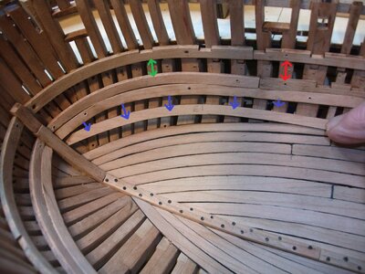

Uwe, thanks for the response. The fit amidships looks good. Using your copy of the photo, the lower thick planks are aligned with laser match marks on the stem so they start in the right position. The plank that has the blue arrows pointing at it has not been installed, I am just showing that the precut plank curvature doesn't match what's needed for the next plank. The red arrow is longer than the green one and I think that is my error in wrestling the thick planks. I am working on the forward set of athwartships curved beams and that will give me a clue as to whether I have an overall hullform issue. Initial dry fits look pretty good. I think/hope I will be able to work around the gap issues above. Thanks again for your input.
Have put together the first set of athwartships beams that go in place over the interior deck planking. Each beam is made out of three pieces that are CNC cut. Each set fit together with only a small bit of trimming and, as assembled, fit very nicely into the bottom of the hull. Had to remove some of the "bolts" that I had placed into the keel earlier, to get a better fit but, overall, I was very pleased with this initial dry fit. I still have to install "bolts" in the beam joints but I have to commend CAF on the fact that the fit is this good at first attempt.
Each of the beams was assembled using graphite laced PVA glue:
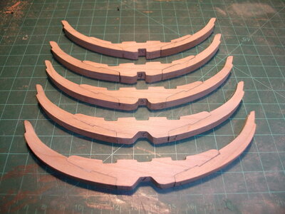
Initial dry fit results:
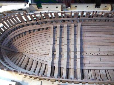
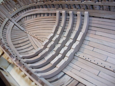
Still have to do a little tweaking but, so far, the fit is better than I could have hoped.
Cheers.
Each of the beams was assembled using graphite laced PVA glue:

Initial dry fit results:


Still have to do a little tweaking but, so far, the fit is better than I could have hoped.
Cheers.
Wow, steady progress. 
Really happy that it appears that the hullform is ok
Have been pressing forward, so far so good. The forward set of athwartships beams went in very well and I have dry fitted the next set of beams on them.
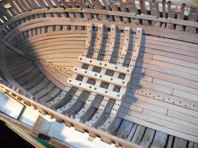
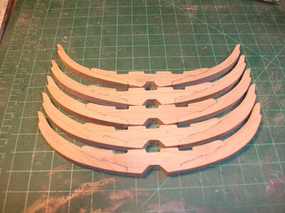
Assembled the aft set of athwartships beams that went together very easily. There is no drawing to match each rib to so you have to glue them on faith but, with this kit, faith is rewarded and once the glue dried, these ribs also fit snugly into the hull with only limited sanding.
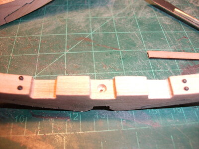
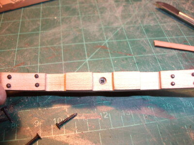
I was struggling with a way to clamp the ribs into the bottom of the hull and came up with the idea to use my track screws again. Drilled and countersunk a hole into the center of the rib and then used a screw to hold the rib in place while the glue dried. Will leave those screws in place as they are fully covered by the beams as shown in the first photo of this post.
Here is the hull with both sets of cross beams installed. Starting to get interesting.....
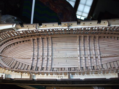
Cheers.

Assembled the aft set of athwartships beams that went together very easily. There is no drawing to match each rib to so you have to glue them on faith but, with this kit, faith is rewarded and once the glue dried, these ribs also fit snugly into the hull with only limited sanding.

I was struggling with a way to clamp the ribs into the bottom of the hull and came up with the idea to use my track screws again. Drilled and countersunk a hole into the center of the rib and then used a screw to hold the rib in place while the glue dried. Will leave those screws in place as they are fully covered by the beams as shown in the first photo of this post.


Here is the hull with both sets of cross beams installed. Starting to get interesting.....

Cheers.
Wow, looking good.
Slowed down a little bit but have made a little progress. The "ammo lockers" are next up. Before starting that, I used some Watco Oil on the forward interior planking to include the lower piece of thick stuff. Brings out the grain of the wood nicely. Then started putting in some of the interior bracing for the deck of the locker
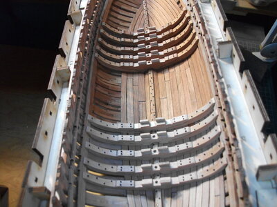
The above photo shows the effect of the oil and shows the bracing pieces.
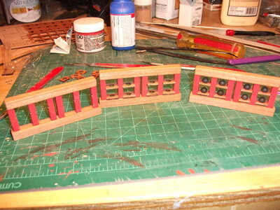
The ammo lockers (fwd and aft) are an interesting build. The instructions show it being done in place. I prefer to do what I can on my bench and then install it on the ship. The below photo shows the three steps of building the mortar round racks. The pre-cut pieces fit very well. The red uprights only required a little trimming to fit in the upper and lower beams. The left rack just has the uprights installed, the middle rack has the shelves for the rounds, and the right rack is loaded up with ammo. Used brass black on the rounds, worked quite well I think.
The next two photos show dry fitting of the racks.
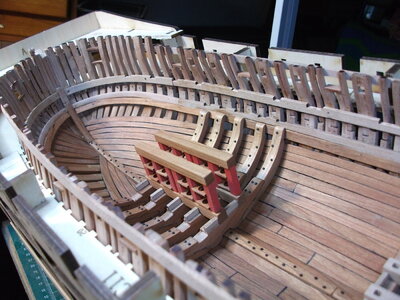
Two racks dry fit above, three below
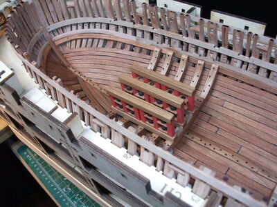
Have to repeat rack construction for the after set. Then the racks are basically enclosed all around and there are some doors programmed for the front end. Having just come from my BonHomme Richard build, I am going to attempt to do some cut aways on the sides of the lockers so that you can see the ammo shelving inside. Have to think on it and measure twice/cut once to make sure I don't screw it up.
Cheers.

The above photo shows the effect of the oil and shows the bracing pieces.
The ammo lockers (fwd and aft) are an interesting build. The instructions show it being done in place. I prefer to do what I can on my bench and then install it on the ship. The below photo shows the three steps of building the mortar round racks. The pre-cut pieces fit very well. The red uprights only required a little trimming to fit in the upper and lower beams. The left rack just has the uprights installed, the middle rack has the shelves for the rounds, and the right rack is loaded up with ammo. Used brass black on the rounds, worked quite well I think.

The next two photos show dry fitting of the racks.

Two racks dry fit above, three below

Have to repeat rack construction for the after set. Then the racks are basically enclosed all around and there are some doors programmed for the front end. Having just come from my BonHomme Richard build, I am going to attempt to do some cut aways on the sides of the lockers so that you can see the ammo shelving inside. Have to think on it and measure twice/cut once to make sure I don't screw it up.
Cheers.
Kurt Konrath
Kurt Konrath
Great looking work on the racks, can't wait to see how you do the wall to allow a view of ammo.
Thanks for the kind comments. It is really a work in progress and a fun project. Am getting better at looking well ahead in the instruction book to see how things come together down the road. Trying to avoid the "Aw crap" moment.
Cheers
Cheers
Very impressive work, looks stunning. I like it very much.
Very good progress and very good looking execution.
It is very interesting also to see the structural differences of the kits between the complete model and the section model I am building in moment
It is very interesting also to see the structural differences of the kits between the complete model and the section model I am building in moment


