BALDER, Vlaardingen Herring Lugger from 1912, scratch build scale 1:50 Plate-On-Frame

And your build log is so comprehensive, it can double as the most extensive instruction manual yet. for a kit. Maarten's idea is certainly something to consider seriously.
Thanks again for your nice words and compliments, Heinrich.
Developing a kit ….. there are only 24 hours in a day, 7 days in a week, etc ……
But the log is free to use for everyone, just buy the needed Evergreen.
Regards, Peter
 
I thought I would make some progress installing some frames at the forecastle.
But the little voice said: "Think again before acting".

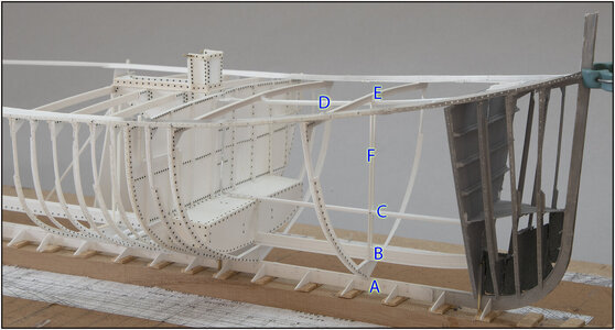
I have to keep an eye on a lot of flowing lines when I continue building at the front:
0205 Lijnen.jpg
-the keel (A) is flat on the base plate, but has a slope of 1.5 dgr.;
-the keelson (B) that runs parallel to the keel from the water tank, but curves upwards at the front;
-the floor profile (C) is slightly curved along the length of the forecastle and running upwards;
-the deck profile (D) in the length that follows the sheer;
-the deck beam (E) in the transverse direction that follows the deck curve;
-the frame itself is standing perpendicular to the waterline, in angle 91,5/88,5 dgr. in respect to the keel.
All of this is divided into 2 halves that must run parallel to each other in length and transverse direction.
Phoe, I didn't make it easy for myself....... ;) but I have mentioned that before ......

That is why I decided to first install halfway the forecastle frame 46 with deck beam. Once installed, I was able to use this frame to secure the alignment of the points mentioned by placing rods (F) between the keelson (B) and the deck profile (E). With intermediate securing to the aligned floor profile (C). The distance between the keel (A) and the keelson (B) is secured by the flange.
The rods are of course parallel to the frame, so perpendicular to the waterline.

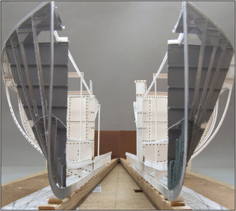
With a different camera angle at the height between the keelson and the floor beam of the forecastle:
0206 Lijnen.jpg
The two rods also had to be aligned with each other.

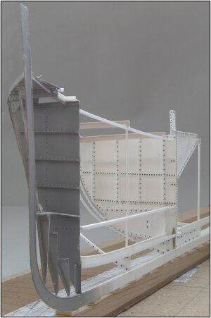
The camera slightly higher, above the floor beam:
0207 Lijnen.jpg
Fortunately, considering the front part that has already been painted, it reminds me that the dominantly visible rivets around the still white parts will soon be visually more attractive.
Regards, Peter
 
I thought I would make some progress installing some frames at the forecastle.
But the little voice said: "Think again before acting".

I have to keep an eye on a lot of flowing lines when I continue building at the front:
View attachment 434809
-the keel (A) is flat on the base plate, but has a slope of 1.5 dgr.;
-the keelson (B) that runs parallel to the keel from the water tank, but curves upwards at the front;
-the floor profile (C) is slightly curved along the length of the forecastle and running upwards;
-the deck profile (D) in the length that follows the sheer;
-the deck beam (E) in the transverse direction that follows the deck curve;
-the frame itself is standing perpendicular to the waterline, in angle 91,5/88,5 dgr. in respect to the keel.
All of this is divided into 2 halves that must run parallel to each other in length and transverse direction.
Phoe, I didn't make it easy for myself....... ;) but I have mentioned that before ......

That is why I decided to first install halfway the forecastle frame 46 with deck beam. Once installed, I was able to use this frame to secure the alignment of the points mentioned by placing rods (F) between the keelson (B) and the deck profile (E). With intermediate securing to the aligned floor profile (C). The distance between the keel (A) and the keelson (B) is secured by the flange.
The rods are of course parallel to the frame, so perpendicular to the waterline.

With a different camera angle at the height between the keelson and the floor beam of the forecastle:
View attachment 434810
The two rods also had to be aligned with each other.

The camera slightly higher, above the floor beam:
View attachment 434811
Fortunately, considering the front part that has already been painted, it reminds me that the dominantly visible rivets around the still white parts will soon be visually more attractive.
Regards, Peter
Good evening Peter. Certainly seems like you have got this in hand. Totally agree re the rivets after painting. Cheers Grant
 
Good evening Peter. Certainly seems like you have got this in hand. Totally agree re the rivets after painting. Cheers Grant
Thanks, Grant. Indeed …… it seems …..
We will see later.
Luckily I deed the earlier painting. Otherwise the black rivets on the white parts would have bothered me.
Regards, Peter
 
Wow, what an incredible job you're doing. Did you also run some preliminary checks on the continuaty of the contours?
Thanks, Johan. I check them also by placing each new frame. Now there is some inequality, but that is due to the flexibility of the frames, mainly in the curves. I can make the main alignement when I am at the point of installing the lengtwise profiles in the kim of the frames. When I have places a few more frames for the forecastle, I can show some curves with some thin strips.
Regards, Peter
 
Hi Peter,

This gives a total different meaning to the saying "plastic fantastic".

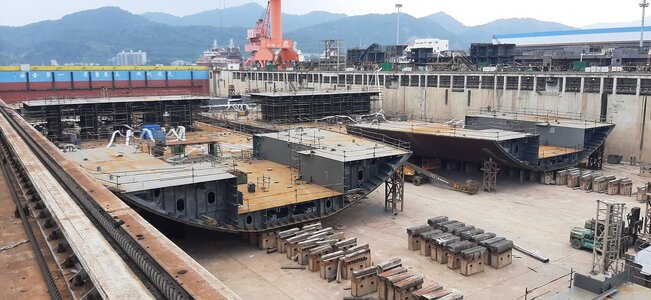
See below a picture I took on a shipyard in China last year, you would feel at home between these sections
View attachment 435054
Thanks, Maarten. Indeed: Plastic is Fantastic! :)
And I am a step further then those builders in China: I build already connected sections ……. ;)
Regards, Peter
 
Last edited:
Back
Top