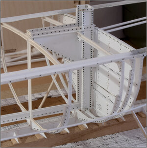
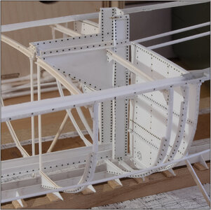
BALDER, Vlaardingen Herring Lugger from 1912, scratch build scale 1:50 Plate-On-Frame

For one reason or another I missed on quite some updates, but man, this build is something else!
Hi Johan. I got also some times no notification of up-dates in followed log’s.
But just on time back for this key-point of the build.
Indeed: something else! Always new challenges to work on. That is why there is plenty of time between substantive contributions.
Regards, Peter
 
Hi Johan. I got also some times no notification of up-dates in followed log’s.
But just on time back for this key-point of the build.
Indeed: something else! Always new challenges to work on. That is why there is plenty of time between substantive contributions.
Regards, Peter
Hey Peter, those random notifications are very odd and sometimes a nuisance, but indeed, back in time.
Your self imposed challenges must keep you well on your toes, especially when considering the flexibility of your construction material. I am still wondering whether or not brass would have given you more rigidity at parts level, but, without a doubt, you ran a trade off between the various material options. Still, given the way you dealt with other projects, I'm confident this challenge will result in another Peter Voogt Special
 
Hey Peter, just wondering when the exact moment was when you realized how much work is ahead of you...?

AMAZING BUILD!
Well, Paul ……
I soon had that feeling..... and it became true when I started to understand the drawings better and better. After the first visits to the real Balder I knew that this would be another 'over-the-year build'.
And with the decision to rebuild the entire construction...... and the choice of material...... I didn't know exactly what I was going to mess up.
I'm already looking forward to setting up the compartments....... but when that is.....
So, no hurry, change plans when necessary ….
I have already quoted an expression from my mother: “A stitch every day makes a shirt sleeve in a year.”
Regards, Peter
 
Thank you for your thoughts, Maarten. When making this experiment I also made a row of punches with the 1mm hollow pipe. Just not shown complete but a half of it is still visible on the right:
View attachment 394138
Then I also have to see what will be left after the parts are painted.
When I am back from holiday I will collect material to make a first frame on the 1:50 scale. To see whether it is all workable on that scale. The BALDER foundation documents also contain 1 old drawing of the 3 frames with watertight bulkheads. It has all the original dimensions, including the profiles used. I can then determine how I can make the rivets: melting, (glue) drops, punching (rondelles) or the resin sheets from America.
Perhaps a smaller hollow pipe, because in the old specifications the size of the rivets is stated as 7/8 and 5/8. Probably in Dutch thumbs, so I can use that for the resit sheets. The maker lists them as representative of 7/8" and 5/8". With different scales, usable ones must be no problem. Of course, it has to be nice in terms of costs with the expected numbers of rivets.
Also some further search, especially in aircraft model making. Because they also use flattened nails.
Regard, Peter
Hi Peter Voogt, just out of curiosity, did you choose this type of material? Thank you Frank
 
Hi Peter Voogt, just out of curiosity, did you choose this type of material? Thank you Frank
Hi Frank. At first, thanks for the visit.
I suppose your question is ‘Why did you choose this type of material’?
Because Evergreen has a very great amount if different profiles, strips, rods etc, it’s easy to handle, it’s flexible and I have seen many great build with this material.
And what Johan mentioned in his answer about brass: I am not familiar with its use and it also has its disadvantages.
Regards, Peter
Hi Peter Voogt, Thank you for responding, a great job , Congratulations. Too bad the project is not on the market. Frank
 
Hello Peter, I'm playing a bit of catch up here, such fascinating work to be sure. The battleship gray paint brings the plastic to life and those rivets are over the top. The internals of your hull will be the main attraction for me, glad you are splitting it lengthwise.
 
Hello Peter, I'm playing a bit of catch up here, such fascinating work to be sure. The battleship gray paint brings the plastic to life and those rivets are over the top. The internals of your hull will be the main attraction for me, glad you are splitting it lengthwise.
Thank you for the nice words, Daniel. I find it a challenge to make the complete internal structure of the ship. But also the interior soon, including the forecastle with the bunks. But also the hold with the stacked barrels. Then the split view is the best to show.
I also think the rivets are subtly expressed in the gray. When I look at the white parts with the black nails I keep thinking: 'mmm...... a bit overdone', but the gray smoothes them out a bit and brings them to the right proportions.
Regards, Peter
 
Received my +200 ordered Dutch herring barrels today.
I had found someone via via via in Madrid who wanted to make the barrels to their specific size.

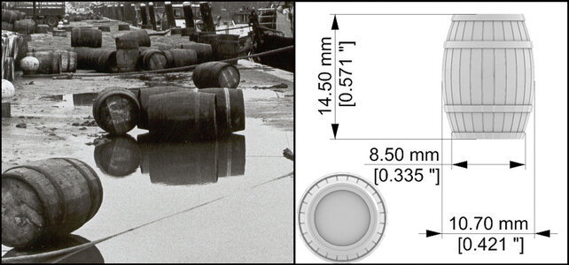
A Dutch herring barrel (harington) had different sizes. The holds and hatches of the luggers are also tailored to those dimensions.
They had a length of 725 mm, a largest diameter of 535 mm and a bottom diameter of 425 mm. With 2x2 hoops.
In scale 1:50 this becomes 14.5 x 10.7 x 8.5 mm:
0173 Barrels.jpg

I have made a rough estimate of the number of barrels that I think I will use in the furnished hold in the port part.
The Balder had 2x9 spaces in the hold in which the barrels were stacked. Just 2 previously posted drawings:
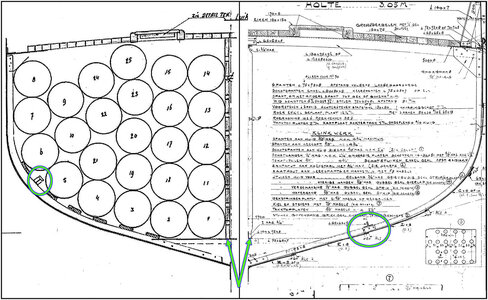
0176 Kim.jpg
The largest frame has 25 barrels stacked on each side.
2x9xx25=450. That's 225 per side.
I'm not going to fill all the compartments, but there will be several on deck as well. So more than enough.

The Madrileen printed slightly more. He equipped his printing floor with barrels as optimally as possible and ended up with 234 pieces:
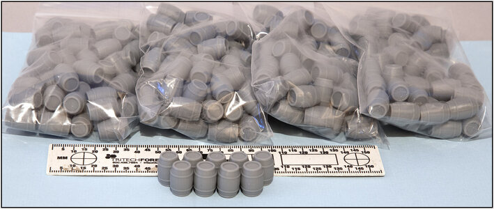
0174 Barrels.jpg
He printed them from gray resin so that they are very sleek and detailed:
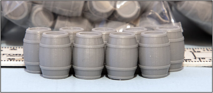
0175 Barrels.jpg
With nice thin seams between the staves.

Again, thinking a few steps ahead:
I am not going to use the barrels yet, but I do need them to adjust the position of the longitudinal profiles in the hold, in the bilge. I have circled them in the drawing above. They are in different places. I'm going to use the position of the left drawing, because it was included with the drawings of the 1st restoration. The drawing on the right is from 1911 of the yard that built the lugger.

The drawings also show the uprights, see arrows, that form the partition in the longitudinal direction. They are on either side of keelson. These are profiles with 10 longitudinal beams. This is different from what is shown in the old photo of the hold with the mast tube + cossing, where struts are visible. But that photo was of the situation when the Balder arrived at the Maritime Museum and had therefore already undergone a few changes. The Balder in its current situation also has these struts. But the hold is now a meeting/exhibition space and must support the deck.

In both cases I can afford to take some freedom (AL-FI) there without detracting from the current situation.
Regards, Peter
 
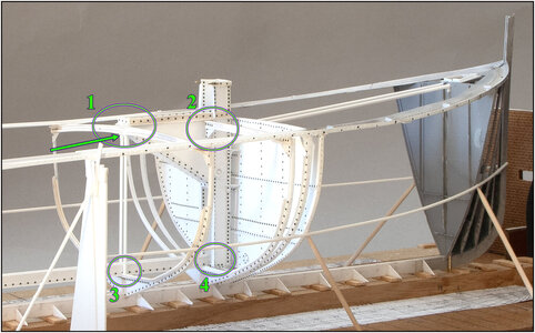
I continued with fixing the mast tube + cossing.
In the process I discovered that this part is crucial for the connection between the parts in front of and behind it and the alignment of it all. Another adjustment to the plan and not yet back to the front part.
Just add the photo for explanation:
0177 Koker.jpg
Circle 1:
The point of the rear of the cossing is supported by the deck beam of frame 33. Underneath the deck beam there will be uprights where the beams will be placed for separation in the longitudinal direction. I can only install the upright once the corner profiles have been installed, which run lengthwise to the rear through the hold. These profiles run under the deck beams.
These start at the arrow, but I cannot add them yet. Then I would have to erect a frame further back. I'll do that later when the bow has all the frames. So new temporary struts made to measure were made here, because ..... that comes with circle 3.
Circle 2:
The mast tube is attached to the watertight bulkhead 39 with 2 small plates. For further fixation, the deck beams 37 and 35 are secured with knees to the side of the kossing. I have attached frame 37 here.
Circle 3:
The keelson runs lengthwise in the hold over the flat parts of the retaining frames. This consists of a standing plate (0.25x4.0 mm) with a round rod (0.64 mm) on top. An angle profile (1.5x1.5 mm) is attached to the bottom. Here's a detailed photo:
0178 Keelson.jpg
The previously mentioned upright is placed on the flat part of the angle profile, which rests against the side of the keelson.
The U-profile in which the side walls will be placed can be seen on the flat part of the retaining frame.
Circle 4:
The keelson is actually attached between the watertight bulkheads 39 and 14. For convenience, I started it in the mast tube. I had to be able to slide both parts apart again:
0179 Keelson.jpg
The keelson in my model therefore consists of 2 parts. Taken apart, each part shows the keelson. Then the total picture of the construction remains visible.
Almost the same as the 'double keel'.

Now the frames 34, 35 and 36, where the deck beam of 35 is again attached to the side of the kossing and has its full support.
Regards, Peter
 
Back
Top