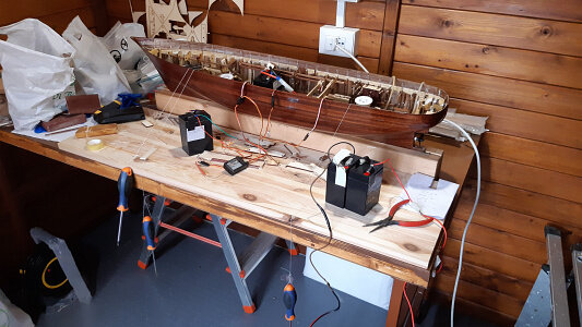
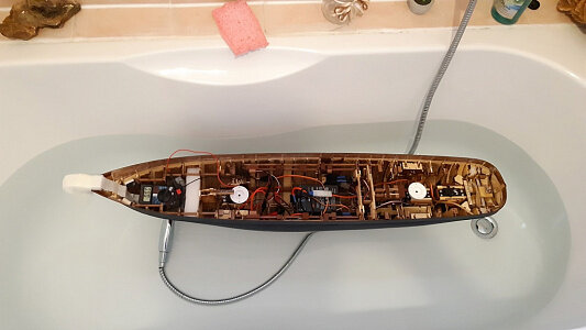
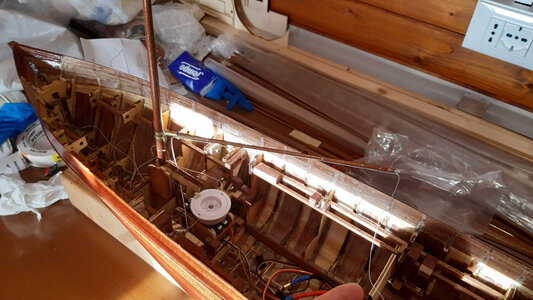
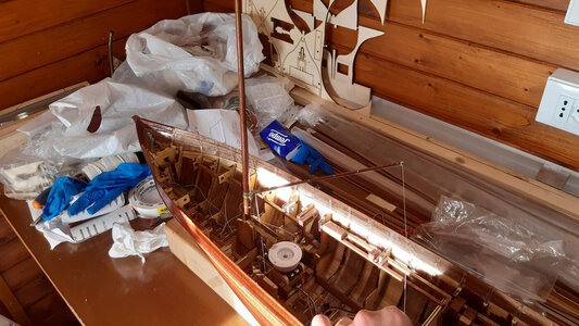
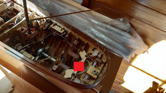
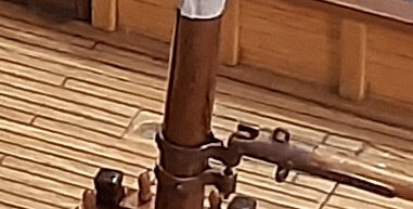
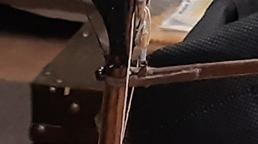
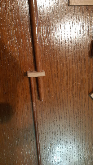
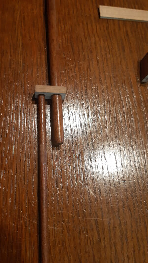
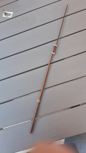
1/60 scale RC model of a schooner, loosely based on a gunboat steamship from the second half of the 19th century.

I wish I’d known about this tool 35 years ago when I built my only plank on frame model boat. I opted for building plastic models after that, only because my career got more involved and I didn’t have the time to devote. I’ve got so much respect for the craftsmanship of the members on here.
Grazie ancora Peter.
Se ti può consolare anch'io l'ho scoperto molto tardi.
Prima dovevo fare molta fatica con acqua bollente e altre soluzioni, molto poco pratiche.

Thanks again Peter.
If he can console you, I discovered it very late too.
Previously I had to struggle with boiling water and other very impractical solutions.
 
Ciao a tutti.

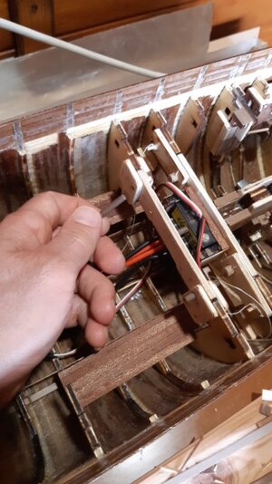
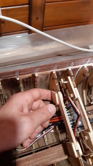
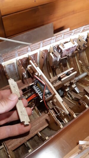
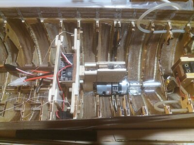
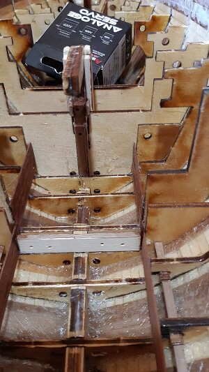
Ora farò vedere come ho posizionato il variatore di tensione (ESC o speed controller) per motore a spazzole.
E' un elemento fondamentale. Riceve tensione dalle batteria e la da al motore a seconda dei comandi radio che riceve. Questi apparati hanno di solito un BEC (Battery Eliminator Circuit) incorporato che fornisce alimenta la ricevente e tutti i servi. Io ho preferito non utilizzare il BEC.
Nei prossimi post farò vedere nel dettaglio il titpo di configurazione elettrica che ho scelto.
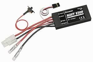
Inizialmente ho acquistato un buon ESC, con un rapporto qualità prezzo davvero ottimo: GRA2880, di Graupner, variatore navale V30R 30 Ah con retromarcia, Tensione di funzionamento 6...12 V, Corrente massima: 30 Ah, Corrente inversa massima: 20 Ah, BEC: 5 V / picco 5 A, Dimensioni 69x31x11mm, Peso 65 g.
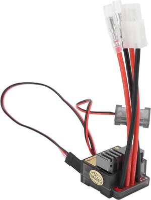
Poi ne ho messo uno da 10 euro, un ESC da macchina. (devo trovare le caratteristiche ma è uguale a quello in foto).
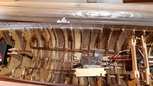
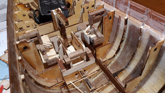
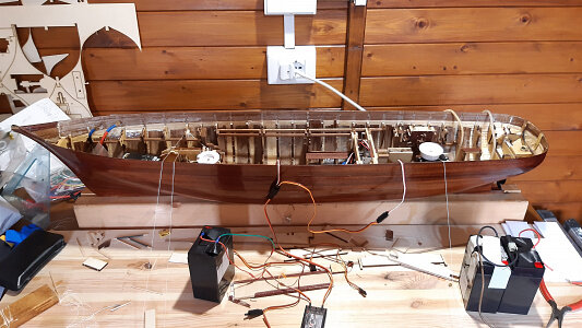
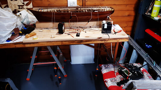
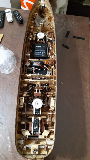
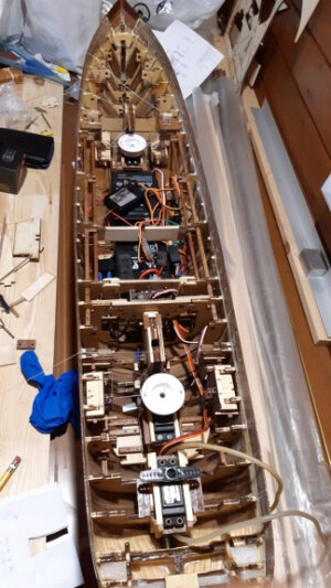
Mostrerò gradualmente come ho disposto i dispositivi nello scafo, prestando attenzione al peso e alle posizioni.
All'inizio c'è molta confusione, poi vedrete in ordine i cavi elettrici e la treccia per le vele.
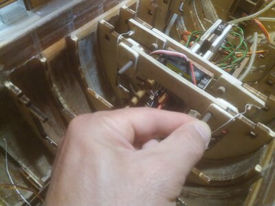
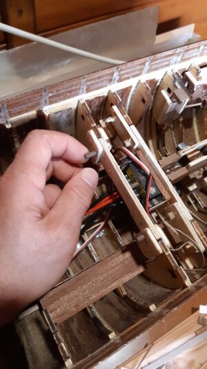
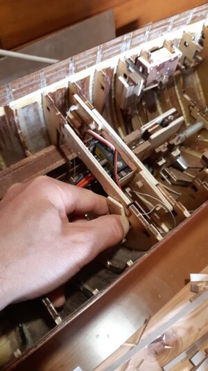
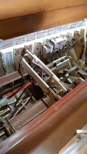
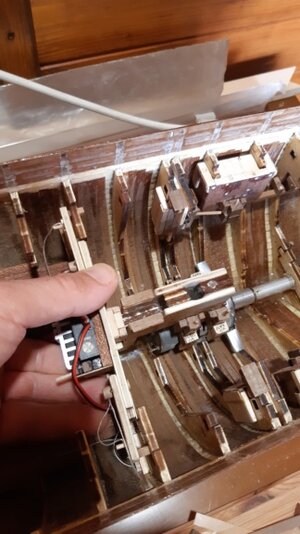
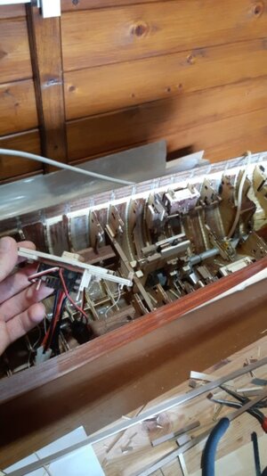
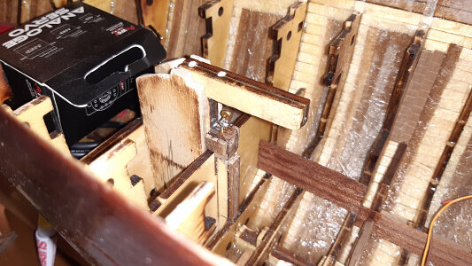
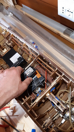
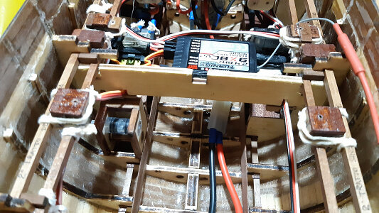
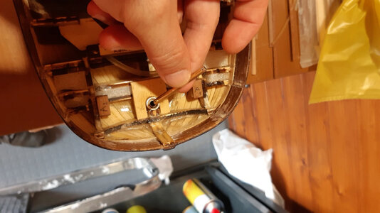
Per posizionare l'ESC ho dovuto creare una struttura tra i telai. Avrei potuto bloccarlo con del nastro biadesivo ma poi ho visto che c'erano dei problemi. O si stacca da solo dopo un po', oppure è troppo difficile staccarsi perché troppo tenace. Infatti dopo aver posizionato il ponte la presa non è agevole e non è possibile applicare forza.
Per questi motivi ho realizzato una struttura amovibile ad incastro. Tutto questo in previsione di eventuale avaria e della necessità di sostituzione.


Hello everyone.

Now I will show how I positioned the voltage variator (ESC or speed controller) for the brushed motor.It's a fundamental element. It receives voltage from the battery and gives it to the engine depending on the radio commands it receives. These devices usually have a built-in BEC (Battery Eliminator Circuit) that provides power to the receiver and all servos. I preferred not to use the BEC.
In the next posts I will show in detail the type of electrical configuration I chose.
Initially I bought an excellent ESC, with a really good value for money.
GRA2880, by Graupner, V30R 30 Ah naval variator with reverse gear Operating voltage 6 ... 12 V, Maximum current: 30 Ah, Max reverse current: 20 Ah, BEC: 5 V / peak 5 A, Dimensions 69x31x11mm, Weight 65 g.
Then I put one for 10 euros, a car ESC. (I have to find the characteristics but it is the same as the one in the photo)

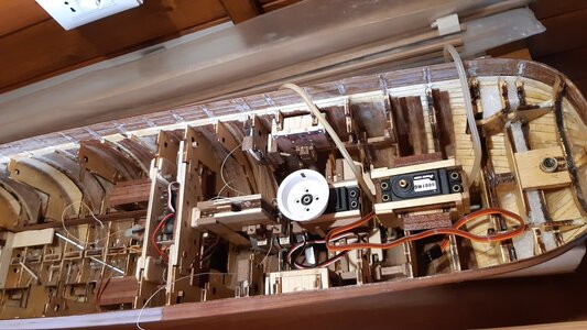
I will gradually show how I arranged the devices in the hull, paying attention to the weight and positions.

At the beginning there is a lot of confusion, then you will see the electrical cables and the braid for the sails in order.

To fix the ESC I had to create a structure between the frames. I could have fixed it with double-sided tape but then I saw that there were problems. Either it comes off on its own after a while, or it is too difficult to detach because it is too tenacious. In fact, after positioning the deck the grip is not easy and it is not possible to apply force.
For these reasons I created a removable interlocking structure.
All this in anticipation of failure and the need for replacement.


variatore graupner.jpg

61mSBObbKIS._AC_SL1500_.jpg

20190924_185041.jpg

20200317.jpg

20200318.jpg

20200320.jpg

20200319.jpg

20200321.jpg

20200322.jpg

20200323.jpg

20200324.jpg

20200402_112449.jpg

20190919_210824.jpg

20200223_101009.jpg
 
Gretings everyone

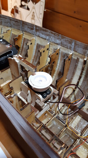
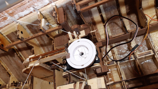
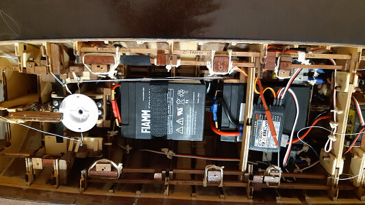
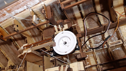
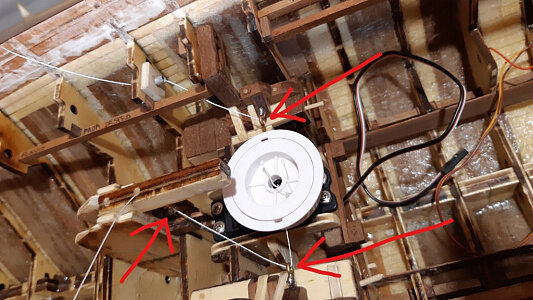
While I insert the photos of the last piece: the bow winch, I briefly describe the electrical connections.

In reality the last piece is the receiver but it is light and small enough not to cause major problems. Fixed with double-sided rubber. Perhaps you will see how it is connected with the descriptive exposition of the other advances.

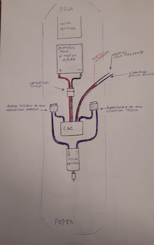
Therefore, I gave up on the first scheme which involved two 6 volt 4.5 Ah AGM lead batteries in parallel connected to the ESC, which powered everything via the BEC, as can be seen in the first sketch.
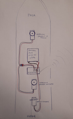
Currently the configuration is this one of the second and third schemes. I separated the drawings.
The first is related to the motor: a battery is connected to the ESC, with large cables passing down, into the frame holes. The cables are interrupted by two fuses. The ESC only powers the motor because the positive of the BEC is interrupted. Logically the cut occurred on an extension cord and not directly on the BEC cables.
The other identical battery is connected directly to the positive and negative of the receiver, which therefore powers the rudder servomechanism and sail winches in parallel.
I'm thinking about improvements.

I was forgetting to write that at that time, longitudinal and transversal reinforcements of the frames were gradually added.


1.jpg

2.jpg

3.jpg

4.jpg

5.jpg

6.jpg

7.jpg

8.jpg

9.jpg

10.jpg

11.jpg

12.jpg

13.jpg

14.jpg

15.jpg

16.jpg

17.jpg

18.jpg

20.jpg
 
Hello everyone

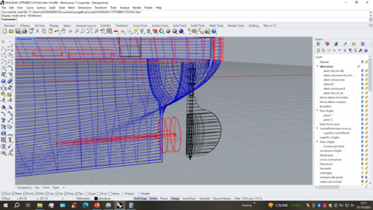
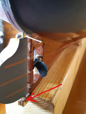
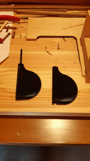
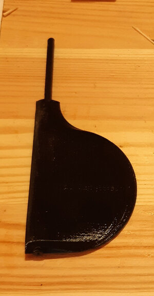
The images are of the rudder.
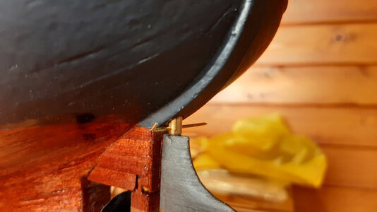
As regards the pin, I proceeded, more or less, in the same way as for the propeller axis. I used brass rod, micro ball bearings, etc. etc.
It is replaceable in case of damage: only the aluminum cylinder that contains everything is glued and unremovable. Just like with the propeller shaft case.

I had already designed the rudder on Rhinoceros and cut it with the laser, because the first intention was to make it out of wood and then paint it.
However, managing to close the volume of the rudder, I had the opportunity to create it with the 3D printer.
I don't remember if the material used was PLA or ABS, however the surfaces are not perfectly smooth but knurled.

Before designing the rudder, however, I knew that this was a great unknown, from many points of view.
Usually, I put two needs on the scales:
one is the need to make a beautiful model, aesthetically pleasing, accurate, coherent from a historical point of view, the other need is to make the model work, that is, to be able to make it move in the water (it must not sink, it must not take on water, it must not tip over, it must move) by motor and sail, therefore it must respond well to all radio commands.
In the model there is, therefore, always a compromise between these two needs, often conflicting with each other.
In the case of the rudder, the balance certainly tipped in favor of the RC requirement.
I painted it and made it look as real as possible, and I could further improve, but it is quite different from the original ones.
If I had made the rudder exactly the same as the real ones of that era, I doubt it would have been able to make turns while sailing.
I have found, over time, that RC naval modelers use transparent plexiglass additions on the rudder, to obtain acceptable performance they either greatly oversize the rudder measurements or, if they can, make a much larger balanced rudder.
When designing it, I had no idea how the rudder would respond in the water.
I was certain that there would be no problems with the propeller in action, in fact, from an airfoil of that kind, hit directly by the propeller flow, I would have expected an excellent reaction even with a few degrees, and a turn almost on placed with the engine at maximum and the rudder above 50 degrees. But with the schooner sailing only by wind it was all an unknown.
The risk is that it does not turn the schooner well when sailing exclusively by wind and is not perfectly identical to those of the time.

As you can see, the rudder is not a simple shaped tablet, but is a real symmetrical biconvex airfoil.
This is intentional. The rudder is made like this because it not only diverts the flow of water, imparting a consequent torque to the ship, but it generates a lift that adds to the other effect.

n.png

45n.png

543n.png

4555n.png

545.jpg

795n.jpg

timoni stampati.jpg

tione n.jpg

n1234.jpg

343n.jpg
 
A very thorough and methodical approach to a seamingly insignificant part. My compliments.
Ciao Johan e Shota70, vi ringrazio ancora una volta per i vostri graditi apprezzamenti.
Tuttavia, il timone è una parte essenziale per il modellista RC a vela.
Mi spiego meglio, sperando di fare una traduzione comprensibile.
Il mio problema potrebbe essere navigare esclusivamente con vento, a basse velocità. Potrebbe essere.
Nella navigazione a motore non ci sono problemi. Il flusso dell'acqua direttamente sull'elica rende efficace qualsiasi timone.
Non ho mai visto nessun modellista RC motorizzato avere problemi di rotazione. Non esiste come problema.
Il problema riguarda le navi a vela.
I modellisti RC a vela utilizzano timoni sovradimensionati. Troppo sovradimensionati per essere realistici.
Se io riesco ad andare a vela ma poi non riesco a virare senza usare l'elica, considero fallito uno dei miei obiettivi.


Hi Johan and Shota70, thank you once again for your kind comments.

However, the rudder is an essential part for the sailing RC modeler.

Let me explain better, hoping to make an understandable translation.

My problem could be sailing exclusively with wind, at low speeds. Could be.

In motor navigation there are no problems.
The flow of water directly onto the propeller makes any rudder effective.I have never seen any motorized RC modeler have rotation problems.
It doesn't exist as a problem.
The problem concerns sailing ships.

Sailing RC modelers use oversized rudders. Too oversized to be realistic.

If I manage to sail but then I can't turn without using the propeller, I consider one of my goals to have failed.
Hello Alessandro,
It is my understanding of sailing large ships (under sail) that the main heading is controlled by the sails, not the rudder. The rudder is used for small course corrections. Even on small sailing boats the jib is used to go through the wind. The manoeuvre is controlled by the rudder, but the jib energizes the turn.
Making a larger than necessary/defined rudder will make an RC ship turn faster, but it remains to be seen whether or not that's really necessary.
Ciao Johan.
Immagino tu ti riferisca alle navi a vela vere e non ai modelli.
Se hai molta esperienza a bordo di velieri ti considero una persona molto fortunata.
Ogni volta che puoi, se vuoi, scrivi di tue esperienze e opinioni di navigazione, in questo post. Ne farò tesoro.
Per quanto riguarda le navi vere, concordo perfettamente con quanto hai affermato, sebbene la mia opinione non valga poi molto e non ho molta esperienza di navigazione a vela. Direi pochissima quasi nulla.
Effettivamente, se si sta seguendo una rotta e il vento non cambia significativamente non c'è bisogno di modificare l'assetto del timone. Come dici tu bastano solo alcune piccole correzioni.
Ad essere precisi, nell'andatura di bolina (forse si traduce "close-hauled", "bowline"), siccome spesso (non sempre) si bordeggia, cioè si procede a zig-zag per risalire il vento, dopo una certa distanza, è necessario turn al fine di mantenere la rotta.
Logicamente se la rotta coincide con l'andatura di bolina, allora non sarà necessario virare nemmeno in quel caso.
Hai prefettamente ragione il timone si usa poco, eppure ogni tanto bisogna usarlo e deve funzionare.
Per quanto riguarda i modelli in scala il discorso è differente.
Un timone perfettamente in scala non farà proprio girare un modello perchè troppo piccolo.
Quando ho iniziato a disegnare con Rhinoceros non avevo punti di riferimento. Dopo qualche anno sono riuscito a scovare dei video di modelli rc a vela su youtube.
Purtoppo hanno poche visualizzazioni, nonostante siano pregevoli, e quindi sono nascosti nel web.
Ebbene, tutte i modelli RC a vela (riproduzioni di galeoni, vascelli, fregate, golette, ecc.ecc.) avevano timoni, almeno tre volte la loro dimensione.
Come ti dicevo il timone sotto effetto dell'elica non ha problemi, ma senza si, ha problemi.
I modelli in scala sono diversi da quelli reali.
Ho fatto delle domande nei commenti di youtube e tutti mi hanno dato la stessa risposta sul timone. Ho interpellato moltissime persone.
A titolo di esempio ti riporto la più recente (RC Cannoniera Olandese N-2 - J.C.J. van Speijk 1835) :
domande:
Se non ti dispiace rispondere, avrei comunque ancora delle curiosità:
Che tessuto hai usato per le vele?
Naviga molto bene, anche con il vento al traverso. Che sistema hai usato per ottenere un'ottima stabilità laterale?
Effettua virate perfette, hai usato il timone originale oppure hai dovuto aggiungere qualcosa?
Naviga esclusivamente a vela oppure ha un piccolo propulsore ad elisa ausiliario?
risposte:
Ich habe dünnen Baumwollstoff verwendet, welchen ich in mehreren Bahnen mit einem bestimmten Profil (abhängig vom Bootstyp) zusammengenäht habe.
Ich habe ein 35 cm langes Schwert mit 6 kg Blei an den Kiel montiert, um die Kränkung auszugleichen.
Hier gibt es keinen Hilfsmotor, ich segle nur mit Wind.
Das Ruder hat die dreifache Größe des Originals (natürlich im Maßstab).
Ich hoffe ich konnte Ihre Fragen ausreichend beantworten und wünsche Ihnen bei Ihrem Modellbau weiterhin viel Erfolg. Sollten Sie noch Fragen haben, können Sie gerne Kontakt aufnehmen.

Guarda questo video, proprio all'inizio, durante la preparazione si vede bene il timone sovradimensionato.

Guarda bene il timone originale (che non avrebbe fatto mai virare il modlelo nemmeno di un grado) e l'aggiunta del timone sotto, con una superfice di circa 30-40 volte maggiore.
L'aggiunta di solito viene tolta quando il modello è in esposizione statica. Anche la chiglia aggiuntica viene tolta.

P.S. Il mio modello, come il tuo, ha un armo aurico. Oltre ai jibs, anche le due rande e le due gaff topsail, sono in grado di risalire il vento e navigare di bolina (bowline). Meglio delle vele quadre.

Hi Johan.

I assume you are referring to real sailing ships and not models.
If you have a lot of experience aboard sailing ships, I consider you a very lucky person.
Whenever you can, if you want, write about your browsing experiences and opinions in this post.
I will treasure it.
As for real ships, I totally agree with what you said, although my opinion isn't worth much and I don't have much sailing experience.
I would say very little, almost nothing.
Indeed, if you are following a route and the wind does not change significantly there is no need to change the rudder trim. As you say, just a few small corrections are enough.
To be precise, when sailing upwind (perhaps translated as "close-hauled", "bowline"), since you often (not always) tack, that is, proceed in a zig-zag to go upwind, after a certain distance, you need to turn in order to stay on course.Logically, if the course coincides with sailing upwind, then it will not be necessary to tack even in that case.
You are absolutely right, the rudder is rarely used, yet every now and then it has to be used and it has to work.As far as scale models are concerned, the situation is different.A perfectly scaled rudder just won't turn a model because it's too small.
When I started drawing with Rhinoceros I had no points of reference. After a few years I managed to find some videos of RC sailing models on YouTube. Unfortunately they have few views, despite being valuable, and therefore are hidden on the web. Well, all the RC sailing models (reproductions of galleons, vessels, frigates, schooners, etc. etc.) had rudders, at least three times their size.As I was telling you, the rudder has no problems under the effect of the propeller, but without it, it has problems.
Scale models are different from real ones.

I asked questions in the youtube comments and everyone gave me the same answer about the rudder.
I asked a lot of people.
As an example, I bring you the most recent one (RC Dutch Gunboat N-2 - J.C.J. van Speijk 1835):
requests:
What fabric did you use for the sails?
It sails very well, even in crosswinds.
What system did you use to achieve excellent lateral stability?
Make perfect turns, did you use the original rudder or did you have to add something?
Does it sail exclusively or does it have a small auxiliary propeller?

answers:

I have found Baumwollstoff verwendet, welchen ich in mehreren Bahnen with a bestimmten Profile (abhängig vom Bootstyp) zusammengenäht habe.I have a 35 cm long weight with 6 kg Blei an den Kiel mounted, um die Kränkung auszugleichen.Hier gibt es keinen Hilfsmotor, ich segle nur mit Wind.The Ruder hat die dreifache Größe des Originals (natürlich im Maßstab).Ich hoffe ich konnte Ihre Fragen ausreichend beantworten und wünsche Ihnen bei Ihrem Modellbau weiterhin viel Erfolg. Sollten Sie noch Fragen haben, können Sie gerne Contact aufnehmen.
I used thin cotton fabric, which I sewed together in several panels with a specific profile (depending on the type of boat).I mounted a 35 cm long centerboard with 6 kg of lead on the keel to compensate for the injury.There is no auxiliary engine here, I only sail with the wind.The rudder is three times the size of the original (in scale, of course).I hope I was able to answer your questions sufficiently and wish you continued success with your model building. If you have any further questions, please feel free to contact us.

Watch this video, right at the beginning, during the preparation you can clearly see the oversized rudder.
Look carefully at the original rudder (which would never have made the model turn even one degree) and the addition of the rudder underneath, with a surface area approximately 30-40 times greater.The addition is usually removed when the model is on static display. The additional keel is also removed.
My model, like yours, has a gaff rig. In addition to the jibs, the two mainsails and the two topsail gaffs are also able to go upwind and sail upwind (bowline). Better than square sails.
 
Last edited:
Ciao Johan

"The manoeuvre is controlled by the rudder, but the jib energizes the turn."

Tu che intendi per "turn"?
Te lo chiedo perchè non vorrei fare confusione capendo male.
Faccio una premessa:
In italiano abbiamo due termini: "virata" e "abbattuta" (o più impropriamente "strambata"). Sono entrambi cambi di direzione e cambi di mure.
In realtà i cambi di direzione sono quattro:
orzare = to luff, to haul the wind, to go windward
poggiare = to bear away Dirigere l'imbarcazione allontanando la prua dalla direzione di provenienza del vento, in modo da navigare con un'andatura più "larga", cioè con le vele più "lasche". E' il contrario di "orzare".
virare = to tack, to go about. Detto anche semplicemente virare, è il manovrare di un veliero per portarlo da una andatura di bolina all'analoga sul bordo opposto, passando con
la prua dalla direzione controvento. La manovra si effettua "orzando" al massimo mantenendo la velocità, portando
quindi la barra "sottovento" e recuperandola al centro dopo il cambio di mura.
abbattere/strambare = to gybe, to wear. Usato comunemente per indicare su un veliero l'insieme delle manovre
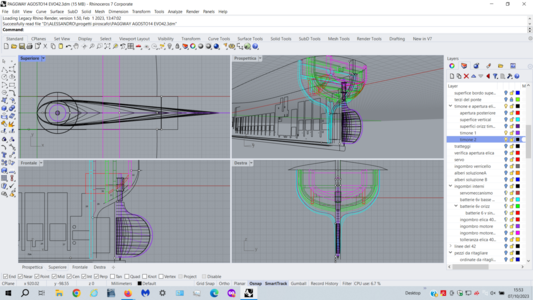
per virare di bordo in poppa.

Lasciando predere le prime due perche non c'è cambio di mure, nella virata il veliero (qualsiasi nave a vela) passa per un angolo morto.
In quest'angolo si va contro vento entro i massimi gradi consentiti dalla bolina stretta, perciò tutte le vele (compresi i fiocchi) non sono in grado di prendere vento e sostenere la manovra. E' solo il timone che fa tutto e la manovra riesce solo se c'è sufficiente abbrivio (course, run, headway), agendo molto velocemente per cambiare mure alle vele.

Spero che qualcosa si sia capito con la mia pessima traduzione.


Hi Johan.

"The maneuver is controlled by the rudder, but the jib energizes the turn."


What do you mean by "turn"?
I'm asking because I don't want to cause confusion by misunderstood.

I'll make a premise:
In Italian we have two terms: "virata" and "abbattuta" (or more improperly "strambata").
They are both changes of direction and changes of tack.
In reality there are four changes in direction:
orzare = to luff, to haul the wind, to go windward
puggiare = to bear away Steering the boat by moving the bow away from the direction of the wind, so as to sail with a "wider" gait, i.e. with "looser" sails. It is the opposite of "luff".
virare = to tack, to go about.
Also known simply as tacking, it is the maneuvering of a sailing vessel to take it from a close-hauled position to a similar one on the opposite edge, passing withthe bow from the upwind direction. The maneuver is carried out by "luffing" to the maximum while maintaining speed, carryingthen the "leeward" bar and recovering it to the center after the change of tack.
abbattere/strambare: to gybe, to wear. Commonly used to indicate the set of maneuvers on a sailing shipto tack downwind.
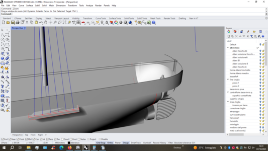
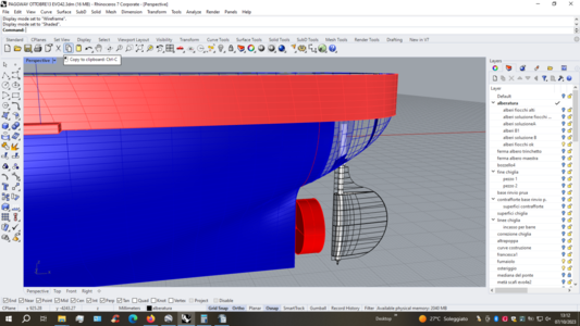
Leaving the first two to be taken because there is no change of tack, in the tack ("virata") the sailing ship (any sailing ship) passes through a dead corner.
In this corner you are going into the wind within the maximum degrees allowed by close hauling (bowline, Up wind), so all the sails (including the jibs) are unable to catch the wind and support the maneuver.
It is only the rudder that does everything and the maneuver is only successful if there is sufficient headway (course, run, headway), acting very quickly to change sail tack.

I hope something was understood with my terrible translation.
Morning Alessandro,

I was mainly referring to "go about", but also on other ways to change coarse or to go windward or the opposite direction, it will be a combination of managing the sheets, to tighten or to loosen the sails, supported by corresponding rudder deflections.
You're absolutely right, when tacking, there's that moment you're dead into the wind, so at that point you need sufficient momentum in order to be able to complete the maneuver. I was taught to keep the jib on the "wrong side" of the mast, when going through the "dead zone" and only to tighten the other sheet once being positively gone about.
While writing this, I realized that momentum is involved when tacking; a RC modelship has a relatively low momentum. This might explain why rudder on RC models are larger than their full scale counterparts. Another issue might be that, and I don't whether or not this applies to RC ships as well, but no doubt someone will know, scaling down airfoils for aircraft does not result in similar flight characteristics, due to the changing Reynolds number ( which is, amongst others, determined by the chord of the body).
Ciao Johan, buongiorno.

Sono d'accordo con te su tutto. Voglio fare solo una precisazione, perchè sentendo citare il numero di Reynolds, mi sono reso conto che sto fuorviando involontariamente il discorso.
Ho paura di aver involontariamente portato chi legge su una via sbagliata.
Cerco di spiegarmi meglio:
Il profilo alare nei timoni non è un requisito richiesto, almeno non sempre.
Molti timoni, sono semplici pale (non profili alari biconvessi) e funzionano benissimo nei modelli a motore e nelle navi a vela vere.
L'idea di creare un profilo alare invece di una pala, è una mia fissazione.
L'idea mi è venuta nell'ipotesi (o nella speranza) che ciò avrebbe incrementato le prestazioni del timone.
Ipotizzavo (o speravo) che la portanza creata dal profilo alare del timone si aggiungesse alla spinta del deflusso di acqua (creato anche da una semplice pala).
Logicamente la portanza aumenta al quadrato della velocità.
Con un'elica attiva la velocità relativa (sottolineo relativa) sul timone è molto maggiore ed è presente anche se la nave è ferma.
L'idea di usare un profilo alare (nelle mie ipotesi) doveva compensare un ingrandimento esagerato del timone (che ho voluto evitare per motivi estetici).

Spero di non aver fatto ancora più confusione. Non rinunciare a discutere con me, anche se ne avresti tutti i motivi, ahahahahahah!

Parlando poi in generale e non specificatamente del timone.
Ci sono notevoli differenze fra modelli e navi vere. Sembra scontato ma non tutti sanno precisamente dov'è la differenza principale.
Nel film "Il volo della Fenice" del 1964, ma anche nel remake del 2004, l'ingegnere aeronautico di modelli in scala, risponde indignato al pilota: "non costruisco giocattoli ma modelli funzionanti in scala".
Afferma che gli stessi principi fisici che si applicano agli aerei veri si applicano ai modelli in scala.
Questo è verissimo e vale anche per i modelli navali ma c'è da considerare il "fattore di scala".
Qui nasce il grosso problema.
Riprodurre fedelmente un galeone o un vascello e cercare di farlo rimanere stabile in acqua, senza che si rovesci, è difficilissimo, perchè le misure lineari si riducono con rapporto 1:1, le superfici si riducono al quadrato e i volumi si riducono al cubo.
Questo cambia tutti i valori e i punti di riferimento (baricentro, centro di carena, metacentro, ecc. ecc.) in gioco.


Hi Johan, good morning.

I agree with you on everything.
I just want to make a clarification, because hearing the Reynolds number mentioned, I realized that I am involuntarily misleading the discussion.
I am afraid that I have unintentionally led the reader down the wrong path.

I'll try to explain myself better:
The airfoil in the rudders is not a requirement, at least not always.
Many rudders are simple blades (not biconvex airfoils) and work very well in motor models and real sailing ships.
The idea of creating an airfoil instead of a blade is an obsession of mine.
The idea came to me in the hypothesis (or hope) that this would increase the performance of the rudder.
I hypothesized (or hoped) that the lift created by the rudder's airfoil added to the thrust of the water outflow (created even by a simple blade).
Logically, lift increases as the square of speed.
With an active propeller the relative speed (I emphasize relative) on the rudder is much greater and is present even if the ship is stationary.
The idea of using an aerofoil (in my hypotheses) had to compensate for an exaggerated enlargement of the rudder (which I wanted to avoid for aesthetic reasons).

I hope I haven't made more confusion. Don't give up arguing with me, even if you have every reason to, ahahahahahah!

Then speaking in general and not specifically about the rudder.
There are notable differences between models and real ships.
It seems obvious but not everyone knows precisely where the main difference is.
In the 1964 film "The Flight of the Phoenix", but also in the 2004 remake, the scale model aeronautical engineer responds indignantly to the pilot: "I don't build toys but working scale models".
He claims that the same physical principles that apply to real airplanes apply to scale models.
This is very true and also applies to naval models but there is the "scale factor" to consider.
Here comes the big problem.
Faithfully reproducing a galleon or a vessel and trying to make it remain stable in the water, without capsizing, is very difficult, because the linear measurements are reduced with a 1:1 ratio, the surfaces are reduced to the square and the volumes are reduced to the cube.This changes all the values and reference points (center of gravity, center of hull, metacenter, etc. etc.) in play.
Good morning Alessandro,

Thanks for your very extensive answer!

With regards to the Reynolds number, I think the hull of a ship has its own Reynolds number (this applies to all bodies in any medium, except may be vacuum), meaning that scaling down from a full scale ship to a smaller level scale will result in a changing Reynolds number and the behavior of the model.
The fact that you use an aerodynamic profile on your rudder doesn't impact the Re of the hull. I do think however your aerodynamicly shaped rudder is be more effective than a flat plate rudder.
Another topic, which I came across is the pivot point of a ship. Much of what has been written about it is way above my paygrade, but if the same applies to a pivot point of a scale model, as it does for the Re,t his also might impact the rudder design.
I also found this article, with some statements about rudder size, but with little explanation.
With your statement in the last paragraph about scaling and the "unequal" reduction of the units of length area and volume, I can only agree and simultaneously assume that not every modeler might be aware of this basic phenomenon.
This only results in a lot of analysis in the design phase of one's ship, if one aims at both the proper geometric ratio's, as well as sailing performance. In the end of the day compromises shall be made...
 
Hi everyone.

Masts topic.
I used walnut rods, of various diameters, (in scale with the 1/60 model) bought in a model shop.
As everyone knows, rods must be tapered. That is, from a diameter of 8 mm measured at the base, for example, we arrive at a diameter of 6 mm at the top.
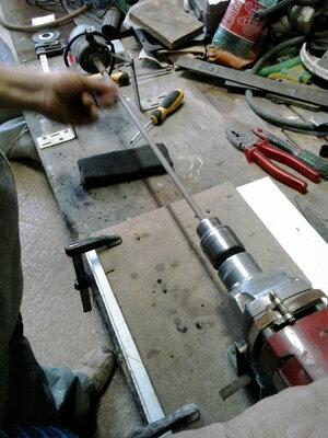
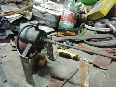
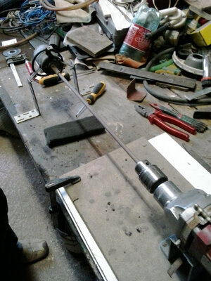
At my father's suggestion, and using his workbench, I tapered the wooden rods with a drill, an electric motor and sandpaper, as seen in the photos. The drill is used to rotate the rod and the electric motor keeps it perfectly aligned while it rotates.
I also tried using the glass method and it is very effective and fast; I did not expect.
In this way I prepared the two mainmast trunks, the two foremast trunks, the two booms, the two peaks and the bowsprit (not in the photo). Everything duplicated to always have a replacement ready.
Logically all the masts have been painted.

As for the peaks and booms movement system, I used two different methods.
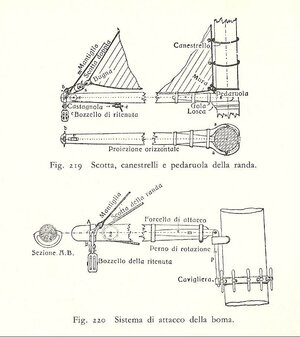
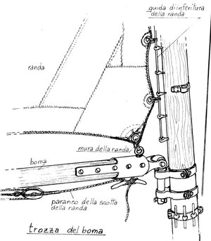
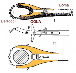
On the peaks I used the oldest one with the gooseneck and the bertocci (it doesn't translate. They are wooden balls. They form like a sort of necklace behind the trozza) as you can see in the drawing.
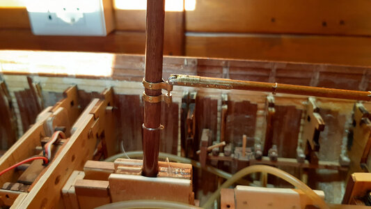
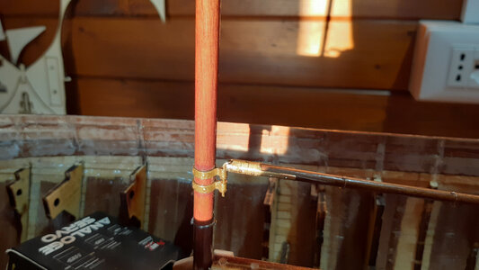
At that time they began to use a method to replace the gooseneck, a steel joint as can be seen in the photo. A parrel.
I made the latter by working a brass rod, with a hacksaw and file, sheets of other pieces of brass.
You can't see it in these photos but I didn't leave the original color of the brass but created a darker, more realistic metal mix with the Humbrols.
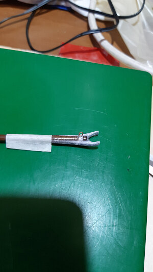
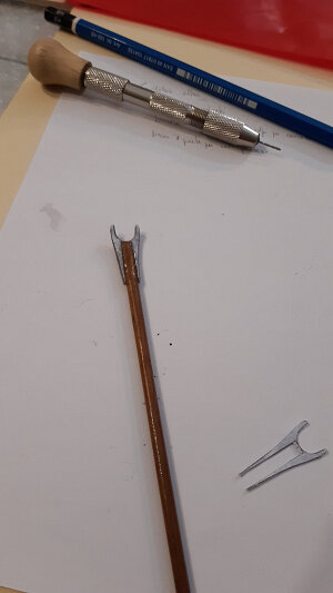
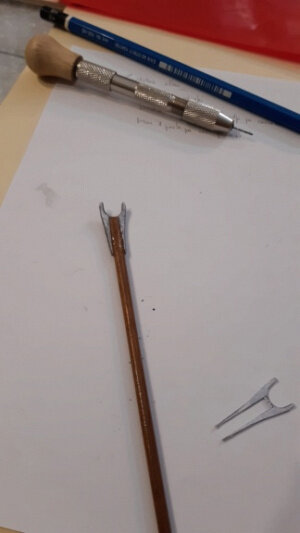
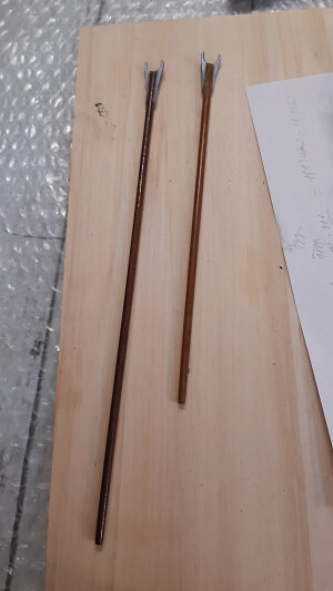
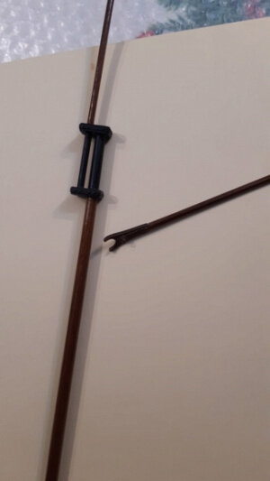
The gooseneck was much more complicated. As you can see in the photo, this is a kind of fork that hugs the mast.
Making it in metal wasn't good for the sake of keeping the center of gravity low.
Making it out of wood was impossible because it was too small and therefore very fragile.
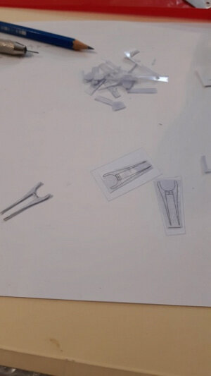
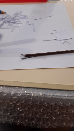
This is why I invented a method that I make available to everyone. I designed the gooseneck with Rhinoceros software. Then I printed the goosenecks and glued them onto sheets of clear plastic. They are just under half a millimeter thick and are the ones normally used in the office. I cut them out and glued them gradually, folding them as needed. Once glued to the peak they proved to be the same as the original and very resistant.
I made a sort of sandwich with all the layers overlapping.

Finally I made the "brown heads" (cap) and the "cheeks" masks.

The masts, as can be seen from the two final photos, are not glued but blocked by a split pin.

n.jpg

2n.jpg

3n.jpg

4n.jpg

5n.jpg

6n.jpg

7n.jpg

8n.jpg

10n.jpg

11n.jpg

12n.jpg

13n.jpg

14n.jpg

16n.jpg

17n.jpg

19n.jpg

20n.jpg

21n.jpg

22n.jpg

23n.jpg

24n.jpg

25n.jpg

26n.jpg
 
Back
Top