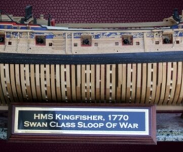
Kingfisher 1770 1:48 POF

just a hobby that I do for fun. Sometimes I take myself too seriously.
Good morning Paul. This statement is the definitive ethos ....(in my opinion).
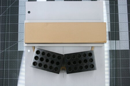
I added some integral nuts to give me the option of a pedestal stand in the future.
and good thinking...

Precise and perfect work as always.
Cheers Grant
 
Great job Paul! You are doing excellent work. But I agree it’s just a hobby and should be fun! So don’t put unnecessary pressure on yourself. You have already exceeded most people’s first ship build on your Vasa. So don’t try to be a master on your second ship! :p
Good advice Dean. It's hard to keep my perfectionist tendencies under control (perhaps you can relate?).
 
That looks great. Nicely done.
Thank you, Jan. I'm enjoying quietly following your AMBITIOUS build!

It‘s looking very good. It‘s nice to see, that you find your way through this difficult part of the model.
Thanks, Christian. I can press too hard, so it was good to remember this is just a hobby. I am looking forward to working on the model again which wasn't true for a few weeks.

Smart idea to add these nuts in the keel.
Yes it is a hobby, but also fun to loose yourself in it. So when it feels good, let it go.
Thanks Steven. How is the drafting coming along?

Good morning Paul. This statement is the definitive ethos ....(in my opinion).

and good thinking...

Precise and perfect work as always.
Cheers Grant
Thanks, Grant. I need to adopt your 'fun' approach more often!

It looks lovely Paul. Also the nuts into the keel looks good. :)
Thank you, Peter!
 
Hi Paul. Why don't you consult the two build logs on the LSS Patrick Henry by Mike Shanks and @DocBlake Dave on SOS? Even though it is not the Kingfisher, I am sure that there will be many areas that are common - seeing both are LSS kits. Then, you also have @tedboat 's build log on the Kingfisher which you can consult as well.


Armed Virgina Sloop. 1:32 Scale POF Admiralty Style. Lauck Street Shipyard

Thank you, Heinrich. I have shortcuts for all of those builds on my desktop. I am using the AVS (Armed Virginia Sloop) builds to help with the framing. Unfortunately, Ted's build report skipped these early stages.
 
Looking very good PaulThumbsup I think I commented on your Vasa build that you are your own worst critic. This project is as near to scratch as you get without actually being a scratch build. The mindset is quite different to building a normal kit.Far more problem solving and considerable thinking time, probably more than actual building.

My best advice is not to box yourself into a corner and leave yourself some wiggle room.Be prepared to assemble the bare bones of the framing even if you leave all the framing in an unfinished state and not glued to the keel. Only then once satisfied, start final assembly.

It is very easy for some builders I follow to post pics of finely finished sections of framing fitted to the model, but they have years of POF building behind them and the ability to think 20 steps infront.

Kind Regards

Nigel
Great advice here Nigel.

And yes, this is much closer to a scratch build than I had anticipated it was going to be. Basically, the kit provides the rough cut out of the pieces similar to what would be produced with a scroll saw. Indeed, on another forum a builder of this kit at one point passingly mentioned that he had abandoned using the kit parts in favor of his own scratch-made parts (and he had purchased the kit when it was selling at a premium).

The instructions are very good but assume more experience than I bring to the game. There are a number of excellent swan class scratch builds out there and I am using them as a guide and adapting what I see to the kit parts and my (emerging?) skill set.

Not taking parts to a high degree of finish is challenging for me. I'll take your counsel to heart and leave more wiggle room going forward.
 
Good advice Dean. It's hard to keep my perfectionist tendencies under control (perhaps you can relate?).
Absolutely, I can relate! But I have to remind myself it's just a model, and to not get carried away.
But I understand the personal need to do your absolute best work and settle for nothing less. It can be a curse! :p I wish I could turn that off, but then I fear people will see subpar work and think that's my best. Therefore I can't bring myself to present bad craftsmanship. :(
However, I have settled from time to time, just to give myself a break. We are human and not perfect, so to strive for perfection is somewhat in vain. However I always say, strive for perfection and settle for your best! ;)
 
The nut is epoxied in place (there is a matching nut on the other end of the ship, but you can't see it anymore).
Aha...I you are thinking ahead of the build with the stand, Hope you have glued those nuts (top and bottom) with the threaded rod in place. If not :eek: the nuts might not be synch with the rod.
 
As I wait for the chisel I ordered...

The instructions now call for the fabrication of the transom pieces (followed by aft cant frames, bollard timberheads, hawse timbers, fore cant frames...). These all strike me as a bit too intimidating, so I thought it would be better for me to just work on some of the square frames.

This required several days of reading and checking out build logs. I learned the names of the parts (cross chocks, floors, first futtocks, second futtocks, and top timbers) and figured out how to decipher the key to find the parts on the boxwood panels - but most of all I studied the drawings provided with the kit.

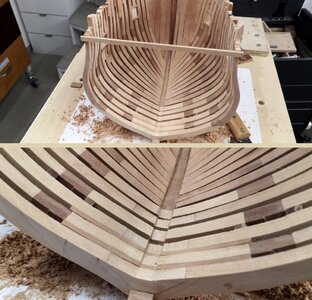
The frames get progressively thinner as they move away from the keel. The bottom bits are 10 inches (adjusted for scale), then 9 1/2 inches, and finally 9 inches. That may not sound like much but it is visible. Just to complicate things...sometimes the flat side of the frame faces aft and other times it faces forward.

* Note: Christian has shared with me that the frame pattern used in this kit is actually not the frame pattern used on the Kingfisher. I have chosen to not correct that because (to the extent possible) I would like to use the CNC cut parts provided in the kit.

Just to further complicate things, there are several types of square frames on this ship, and it will take a great deal of care to get everything in the right place.

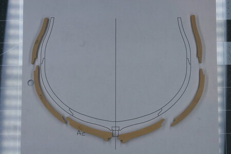
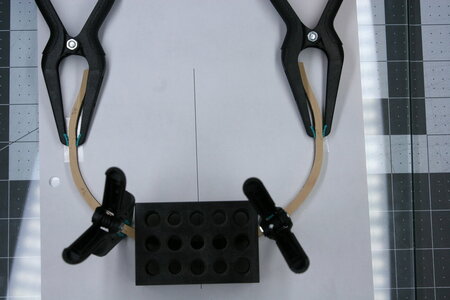
I have learned from other build logs that it is wise to build frames on a perfectly flat surface. I am using a piece of glass. I am also using double sided tape to hold the parts in place on the pattern:
IMG_9331.JPG

IMG_9333.JPG

IMG_9334.JPG

You will have noticed that the joints between pieces are scarphed. This is not correct. There should be chocks on the inside of the frame. My plan is to simulate the chock by adding the other half of the scarph (this will only provide a visual difference on the inside of the frame - the look on the outside of the frame will be the same).

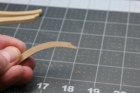
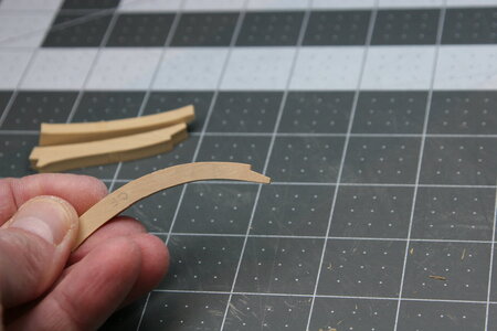
The scarph cuts on the pieces are generally very precise - I have only had to modify a few thus far. Oh, I did have to sharpen the inside corners as the CNC bit leaves it round:
IMG_9339.JPG

IMG_9341.JPG

And now I need some instruction.

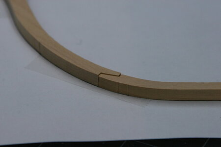
Where the timbers step down in size...how do I handle the scarph (well, in the future this will be half of the chock)? Leaving it staggered as you see below just seems wrong:
IMG_9335.JPG

My solution was to pare down the half of the chock that is on the narrower piece:
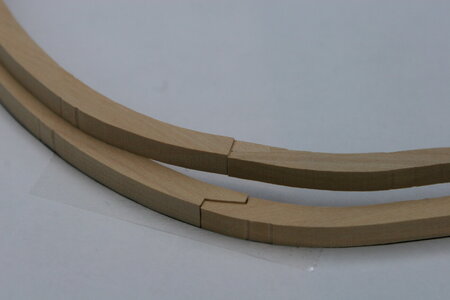
IMG_9337.JPG

Before I do that on several hundred chocks I need to know if this is the correct solution. Thanks for your help!
 
Last edited:
I can only show this example where it is stepped at the chock…
42BA236D-7F10-4D92-B91B-B09F2F590A79.jpeg

However be careful and study the plans and look at the side view. See your reference photo below…
B72A48C0-E2D1-4DA6-AEB7-73BB2A4F42C2.jpeg
As you can see, some of the the frames are stepped such that there is no flat side. ;)
So if it were me, I would take it one frame at a time, and determine frame orientation and how it is stepped, and use spacer blocks.
This build will require more studying than cutting and sanding! ;)
Hopefully someone with more experience will chime in soon!
 
I have learned from other build logs that it is wise to build frames on a perfectly flat surface. I am using a piece of glass. I am also using double sided tape to hold the parts in place on the pattern
Paul,

my experience with double sided tape is not as good as with rubber cement (for example Marabu Fixogum). The adhesive of the tape is mostly to strong, and is not as easy to remove it from the frames.

Make yourself two copies of the DoF Plan and give each frames a number. Now you can mark each frame which you have prepared at the plan and write the number with a pencil on the frame. (I use the number of the station lines followed by a small a (after) or f (fore) for this task). I doN't know if the kit uses a jig. If not I can only recommend to prepare one.

Your proces is lookinge very well structured. I wish you a lot of meditative hours building all the frames of the sloop.

The frames get progressively thinner as they move away from the keel. The bottom bits are 10 inches (adjusted for scale), then 9 1/2 inches, and finally 9 inches.
The frame design is in this detail simplified (what is for the scale of your model absolut fine). At the original ship it's more complicated, but you can show this only at 1/36 or another bigger scale.
There are two fully shifted timbers also in the original drawing of Cygnet. They are build wrong at the beautyful model Dean shared with us. The thickness of the futtocks is given by the dimenison. The problem at this model is that the chocks are not build correctly. The width of the chock has to be the whole with of both frames.
 
Back
Top