
Phenomenal work.

- Home
- Forums
- Ships of Scale Build Logs
- Super Detailing Static Models / Other Genres
- Historical Trailways, Guns, Aircraft, and Cars
You are using an out of date browser. It may not display this or other websites correctly.
You should upgrade or use an alternative browser.
You should upgrade or use an alternative browser.
1/12 scale Alfa Romeo 8c 2300 roadster build log [COMPLETED BUILD]

It’s looking great and very real what you are showing us, François.
")
Because ‘Builder’s Leeway’ sounds good, perhaps it time for BL-AL-FI.
Regards, Peter
About this quote: In the Bluenose area Dean introduced ‘Artistic License’. And a bit later we added ‘Free Interpretation’. Then ‘AL-FI’ was born, who is looking over our shoulder and nods when we have neatly 'solved' something. I am sure, AL-FI was nodding a lot of time by many of your posts.Let's just say that I used a lot of 'builder's leeway' for lack of a better term.
Because ‘Builder’s Leeway’ sounds good, perhaps it time for BL-AL-FI.
Regards, Peter
Finaly got the dash finished. The crackeled effect was very hard to do. It took 6 tries and it's still not exactly what I was looking for but it will have to do. It stems to be an extremely random process, you can repeat the exact same steps, with the exact same thinning and drying time of paints and you will never get the same result. Here are some shots starting with, as usual, the ref car. 
and my version


Then I did the front grill.
Here is the ref car
Made a stencil to paint the number

And my take ( sorry about the lighting)
I still have a decal to install, the radiator cap and the lockwire and lockbolts.
and my version
Then I did the front grill.
Here is the ref car
Made a stencil to paint the number
And my take ( sorry about the lighting)
I still have a decal to install, the radiator cap and the lockwire and lockbolts.
Excellent work!
Started the engine today. I redid the pedal assy. I kept the same plastic levers but since my intention is to have a working brake pedal, I changed the pivot shafts from plastic to aluminium. The new shafts will go thru the engine block. That way, I'll be able to add a lever to actuate the brake. Also started on adding bolts.
The kit's pedal assy

The modifier pedal assy
Some bolts added( left)
The kit's pedal assy
The modifier pedal assy
Some bolts added( left)
There's something missing in this kit compared to the larger scale (1/8) equivalent from the Pocher company. A working engine. So being a mecanical guy, (and nayve to much time to spare) I just could not build this engine without at least trying to but in working pistons. I know it's stupide because nobody would know they are there except me. That being said, I figure I can at least see what the cost of 3d printing the parts would be. So I started by 3d modeling an insert that would fit inside the kit's engine bloc and fitting 8 pistons, 8 connecting rods and a crank shaft. My goal would be to be able to move the pistons using the crank handle these cars had at the front. Maybe I could cut a small window somewhere on the engine block so the moins parts could be seen.
Here is a small video showing the working pistons.
View attachment 20230215_222103.mp4
Here is a small video showing the working pistons.
View attachment 20230215_222103.mp4

Maybe you can modify some thingiverse engines. Two 4 cylinders properly scaled with a connected crankshaft would make life easier. I was considering this option for other models. I would use petg silver filament, it comes out almost ready. Hope it helps
I received the 3d printed parts I was waiting for. Not the bloc and pistons but a fuel diverter, tack bracket, radiator cap and a 4 way hydro fitting. Turns out it was pretty cheap, 20$ for 5 of each! Here are some pictures.
The printed parts as received
Radiator cap with scratch built polished aluminium bezel around the decal
And the real one
The tack bracket with aluminium bezel, aluminium tack face, tack needle made out of a piece of white thread and clear plastic lenze
The 4 way valve with piping and scratch built lever installed on dash
The fuel diverter (not in final location) with scratch built selector lever (the selector is a bit too wide, I think I'll redo it)
And the real part
Did a lot of very detailed work today. I finished piping the 4 way valve mounted on the dashboard and the fuel diverter.
The real 4 way valve
the fuel diverter

The real fuel diverter
I also tried my hand at installing some wirelock bolts and twisted wire. I bought 3d printed wirelock bolts from Unobtainium in the UK. The bolts come with a correct sized wire but it's copper which is not correct. I had some 7 strand cable left over from my Shark 24 build so I removed the plastic coating and was left with 7 strands of .003in dia which come to .036in scaled up.
Here is what my first try looks like.
And the real thing
The .003in wire I'm using
The real 4 way valve
the fuel diverter
The real fuel diverter
I also tried my hand at installing some wirelock bolts and twisted wire. I bought 3d printed wirelock bolts from Unobtainium in the UK. The bolts come with a correct sized wire but it's copper which is not correct. I had some 7 strand cable left over from my Shark 24 build so I removed the plastic coating and was left with 7 strands of .003in dia which come to .036in scaled up.
Here is what my first try looks like.
And the real thing
The .003in wire I'm using
Did some bodywork today. I glued the cockpit to the fuel tank and installed the fuel overflow and delivery fittings. The overflow fittings are mounted on top and the kit calls for two 90deg fittings going to either side of the body with rubber tubing attached. My ref car is a bit different, it has one 90 deg fitting on the drivers side and the other looks like a breather. Instead of the rubber tubing, it as a boby colored copper tubing going down and thru the drivers side rear deck. The tubing is held in place using very small aluminium clamps.
Breather and 90 deg fitting with copper tubing on ref car
My breather, 90deg fitting and copper tubing
Aluminium clamp
Then I did the delivery tubing. Again, my ref car is different from the kit. On the kit, the two fittings are too high and have ordinary rubber tubing attached. On the ref car, the fittings are located much lower on the tank ( which is logical with the lower one being probably for the reserve) and instead of the plain rubber tubing, they have a spring wrapped rubber tubing.
Spring wrapped tubing on ref car
My spring wrapped tubing and relocated fittings
How I made the spring
It's starting to look more and more like a car. Here's what I did today
1-painted the body

2- finished the fuel spring wrapped lines
3- finished the fuel overflow line and a bit of wirelock
4- installed the gas cap, and it opens
5- took some pictures with a few parts assembled just for fun


1-painted the body
2- finished the fuel spring wrapped lines
3- finished the fuel overflow line and a bit of wirelock
4- installed the gas cap, and it opens
5- took some pictures with a few parts assembled just for fun
- Joined
- Apr 21, 2018
- Messages
- 509
- Points
- 268

First time here.....and extremely impressed with your attention to detail.
However, it's clear you've never done any lockwire work for real.
The wire doesn't just pass straight through a fastener....
 www.aviationhunt.com
However, it's clear you've never done any lockwire work for real.
The wire doesn't just pass straight through a fastener....
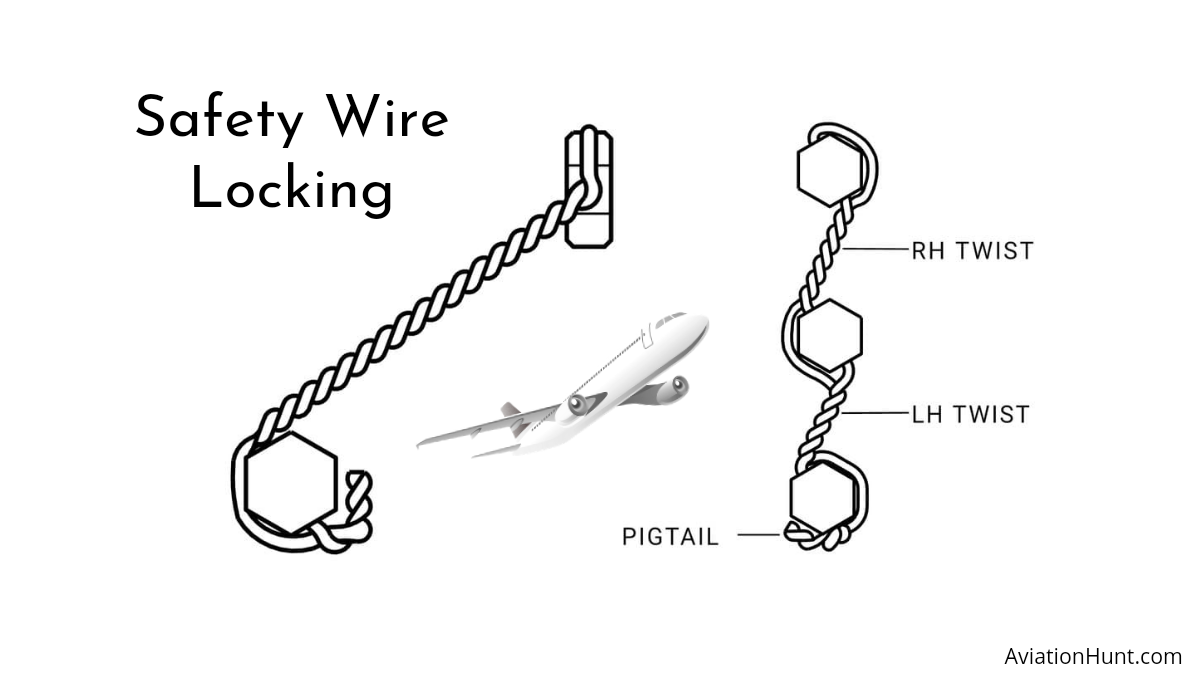
How to do safety wire locking - AviationHunt
Safety wire locking is the method to lock the nut in place after tightening with the bolt using a lock wire. A piece of stainless steel wire passes through a
Pugwash, I do know. Try doing it at this scale and let me know how it turns out. Thank anyway for the comment.
- Joined
- Apr 21, 2018
- Messages
- 509
- Points
- 268
Hi Francois.
I was only hinting that as you're going to include an 'impression' of lock-wired fasteners, it would be far more convincing if a short twist between nuts/bolts, set at a slight angle would appear instantly more authentic, which, after all is the impression you're after?
Please don't take my suggestion as criticism; your model is superb and a credit to your vision and skills.
Hey pugwash, don't worry, no offence made or taken. I had to make a compromise between having a nice enough looking twisted wire or a thru to reality installation. Althougt I would like for my skills to be limitless, they're not so I went with the nice enough look. I do have an idea of how I could twist the wire and have the proper install. I'ii give it a try and let you know if it works.
Excellent model work and craftsmanship!

Wow Francois what a beautiful model.
Thank you all!! I'll be taking a break for a little while, I'm off to ski in the Canadian rockys for a week!!
I'm back from my week of skiing ans what a week it was.
I've received my 3d printed parts for the engine. There's a lot of fitting and twiking to do but it should be a lot of fun!

I've received my 3d printed parts for the engine. There's a lot of fitting and twiking to do but it should be a lot of fun!