William Keltridge's 6th rate ship – reverse engineering the plans of 1684

Joined
Apr 26, 2023
Messages
383
Points
323

Location
European Union
.​

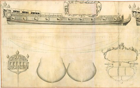
Those interested in the subject are familiar with the existence of a collection of drawings made in 1684 by William Keltridge, an official (not a shipwright!) of the English Royal Navy. One looks in vain for valuable reproductions of these in today's publications, and one might even get the impression that they are undervalued for some reason.

Indeed, even a rather cursory assessment of these drawings makes it clear that they were completely unsuitable for the construction of real full-scale ships. Numerous mistakes of various kinds, huge drawing inaccuracies, inconsistencies or incompatibility of the projections are obvious proof of their purely decorative character.

In spite of all these shortcomings, Keltridge's drawings have still something very valuable and hitherto unexplored – they contain a method of design that has nevertheless, though not easily, made itself readable (even if these drawings have been used in some way so far, it has been rather in an unreflective way, i.e. without understanding or adequately explaining the conceptual methods employed by Keltridge).

Of the portion of the Keltridge's drawings available to me, and acquired earlier in some magical way by Martes (they are not normally publicly available), for more detailed analysis I have chosen the 'plan' of the sixth rate ship for the proper reason only that it is of better quality than the others.

The plate in its entirety, containing two 6th rate ships, both identical conceptually like most, if not all of the other Keltridge's 'designs':
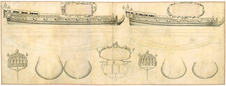
J8582_5000x.jpg

Part to be examined:

J8582_5000x - Copy.jpg

.​
 
Last edited:
.​

Many thanks, Marc. Somewhat in contrast to showing the entire tedious process as for the Ö 3 model (Naseby 1655 thread), this time it will be rather immediate presenting of the results obtained. So I anticipate a few posts at most, but who knows...?

* * *​

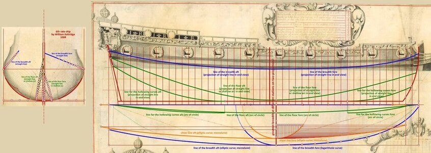
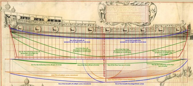
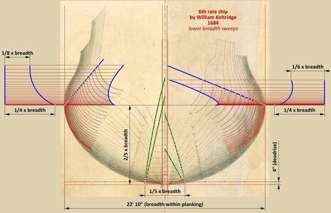
It must be said at once that it is rather pointless to look for exact dimensions and proportions in these 'plans', due to the numerous inconsistencies and inaccuracies (although for some of its elements it turned out to be possible, e.g. breadth of the floor is 1/5 of the hull breadth, and the stem radius is equal to the breadth of the hull without planking, and so on).

One of the draughtsman's most fateful mistakes was the adoption of a different stations for the largest hull breadth in plan view and sheer view. As a result, Keltridge himself got lost in the numbering of the stations, and later, drawing the contours of individual frames on the body plan, he combined points from different stations! Also, the general location of the greatest breadth of the hull, almost at the middle of the keel length, raises serious doubts. Unlike some others, this particular error had to be repeated in order to obtain a good approximation of the shapes and to reproduce the way of drawing.

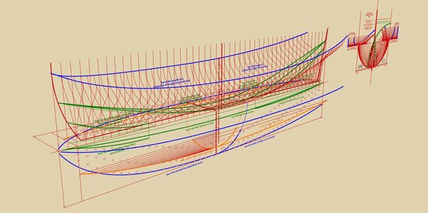
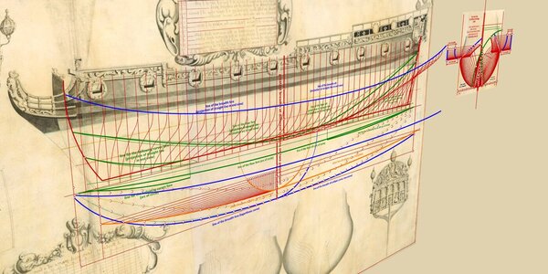
The main design lines on the plan view, described textually in the following diagrams, are primarily ellipses (obtained by means of the mezzaluna transformation) and arcs of circles, but also the first known to me occurrence of a logarithmic curve in the ship's drawing of English origin (for the narrowing line of the breadth fore), replacing the customary up to then line combined from two arcs of a circle.

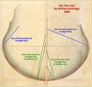
In the sheer view, these main design lines were most likely created by projecting straight sections previously drawn on the body plan (alternatively, but much less likely, they are curves composed of two or even three arcs of circles, which, however, gives a worse fit and particularly ugly-looking wavy lines on the body plan).


ViewCapture20230624_002127.jpg


ViewCapture20230624_002205.jpg


ViewCapture20230624_002255.jpg

.​
 
Last edited:
.​

Despite the aforementioned contraindications, I nevertheless decided to give the dimensions of the design grid and basic elements of the frame contours as well, in proportion to the breadth of the hull. These should be perceived as giving the best results rather than originally intended by the draughtsman, which may or may not be the same. Primarily for a better, general orientation to the specifics of the ship design at the time.

Normally, up to this time or so, frame contours were not drawn on paper at all in the real production context (except for the main frame), but immediately on the mould loft in the shipyard. This may be the main reason why the frame contours on this plan are drawn so sloppily, as is indeed the case with the equally decorative extant 'plan' of London 1656.

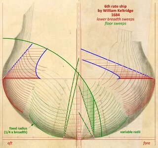
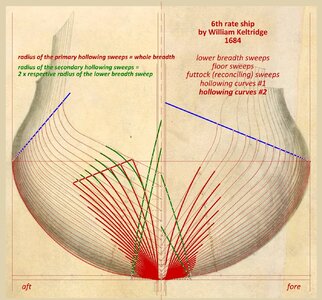
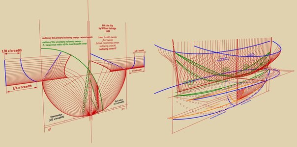
To begin with, the lower breadth sweeps. As can be seen, in this case variable radii were employed for both the fore and aft halves of the hull. The way they are plotted is shown in the diagram below.


ViewCapture20230624_130431.jpg

.​
 
Last edited:
.​

Next in order are the floor sweeps. This is the third case found of variable floor sweeps employed in the 17th century (for the fore half of the hull), confirming the conclusion that this was a standard and quite widely used conceptual method of achieving the smooth shapes of ships' hulls at that time. It should be recalled here that corrective diagonals were not yet imported from the Continent, and design waterlines were just beginning to come into use.

For the aft half of the hull, the use of fixed radius floor sweeps was sufficient to achieve satisfactory shapes.


ViewCapture20230624_152533.jpg

.​
 
.​

:)

Thanks! And fun in this quasi-detective work :).

* * *​

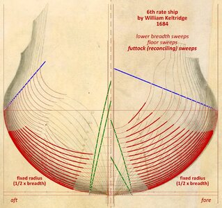
Futtock sweeps. Almost nothing to comment on at this stage. So just that these reconciling sweeps all have a fixed radius and were plotted tangentially to the curves already drawn. Using a wooden template.


View attachment 381214

.​
Dear Valdemar,
I am amazed every time again by the knowledge you have in the field of ships and other professional fields, I learn a lot from you .
Thanks for sharing this with us
 
.​

Thanks @shota70 for the appreciation. To be honest, I too am learning something new with each successive venture like this :).

* * *​

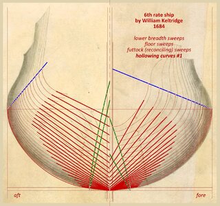
In this case, the hollowing curves are applied quite simply. First, straight sections were drawn connecting the co-ordinates taken from the pre-defined lines for this purpose (shown in the first diagrams), and tangent to the contours of the frames. Then, in the second step, arcs tangent to these straight sections were plotted. In the fore section, these are just single arcs. In the aft section the same, except for the last few stations, where secondary hollowing arcs are added. The way they are drawn is shown in the second diagram.


ViewCapture20230624_181906.jpg


ViewCapture20230624_195441.jpg

.​
 
.​

To conclude, a few more renders, showing, rather as a curiosity, the 'analytical work station' in perspective projections.

* * *​

If one is to judge Keltridge's set of draughts by this one, it must be recognised that the low drafting standard, in terms of precision, tends to put them more or less in the category of hand-drawn sketches. At the same time, it is quite clear that Keltridge knew what to draw and how to draw it, and consequently hitherto unknown or obscure data can be found in his 'plans', shedding more light on the design techniques used at that particular time and place.

From the research point of view, they seem to deserve more than just an occasional mention in modern publications.

Thanks for looking,
Waldemar Gurgul

ViewCapture20230625_184002.jpg

ViewCapture20230625_184217.jpg


ViewCapture20230625_184317.jpg

.​
 
Last edited:
Back
Top