You are using an out of date browser. It may not display this or other websites correctly.
You should upgrade or use an alternative browser.
You should upgrade or use an alternative browser.
USS Gambier Bay (CVE -73) 1/350 by Hasegawa with Hasegawa photo etch [COMPLETED BUILD]
- Thread starter Will @ Trilogy
- Start date
- Watchers 15
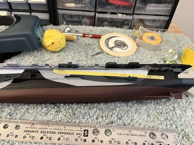
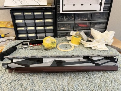
Davidp i'm very confused with you last post. If you look at the previous page you'll see a photo of Gambier Bay port side and the post before the photo is a photo of my Gambier Bay port side matching the Naval Heritage photo 80-G-170034. So this leave me confused.
the Naval Heritage photo matches the port side of the drawings you downloaded off the net but parts of your paint work does not match either. look at the 5-O pattern between the midship's black & the stern black, does it look like this in this link? https://www.navsource.org/archives/03/0307326.jpg
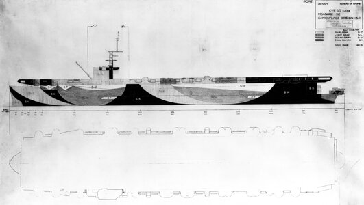

Alright Davidp this post makes sense and with studying I can see the 5-0 patterns are both off. I'm looking at the port side trying how and if I'll fix it. While you're at it on the sides of the ship are ladder steps moulded into the model, on the actural ship are these ladder steps welded to the side?
that tape does not need to be there as it appears that the top of that 5-O pattern is good but the bottom part is wrong as in to slim. the bottom right corner of that pattern should be moved forward just in front of the hull platform painted in 5-O but at the waterline.
Completed the port side camouflage with a close approximation of the actual ship pictures. The pictures taken of the ship definitely show discrepancies between the navy drawings and the what was painted on the ship.
A picture as I feel is the good approximation.
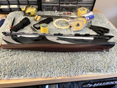
During this process I had long discussions with the Admiral about whether the ship photographs show 4 colors or 3 colors. The Admiral feels that the 5-P color was not used but instead the 5-L. I can definitely see her point as the photos have shadows making it hard to determine a difference between 5-P and 5-L. I rebelled and used 4 colors and the Admiral admitted it looks good.
A picture as I feel is the good approximation.

During this process I had long discussions with the Admiral about whether the ship photographs show 4 colors or 3 colors. The Admiral feels that the 5-P color was not used but instead the 5-L. I can definitely see her point as the photos have shadows making it hard to determine a difference between 5-P and 5-L. I rebelled and used 4 colors and the Admiral admitted it looks good.
Ugh!!!
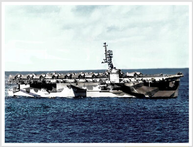
Thanks Davidp. I found this photo on the ussgambierbay.org giving a nice view of the forward portion of the camouflage with the middle vague due to reflections and shadows.
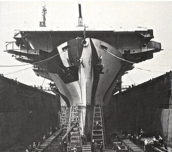
In dry dock April 1944. It appears that the camouflage is being added and the port side is not as complete as starboard.
I was having trouble with the shape of the forward BK camouflage as on the navy drawing it gave the impression of not being as low to the waterline as this photo. Studying both drawing and photos I just couldn't reconcile the differences, until I realized the drawing is 5' above the waterline. Now I see the difference so back to tapping the BK pattern.

In dry dock April 1944. It appears that the camouflage is being added and the port side is not as complete as starboard.

I was having trouble with the shape of the forward BK camouflage as on the navy drawing it gave the impression of not being as low to the waterline as this photo. Studying both drawing and photos I just couldn't reconcile the differences, until I realized the drawing is 5' above the waterline. Now I see the difference so back to tapping the BK pattern.
that forward bk is Not 5' above the waterline but closer to 15' above the waterline. look at the guy halfway up the port ladder at the bow for scale height. those ladders/scaffolds reach to the top of the waterline on the starboard side. camo is not being put on as most likely the lower hull from the waterline down is being scraped clean then repainted.
Last edited:
No I understand and that is what caused my confusion. The navy drawings are shown at 5' above the waterline so when I compared it was HUH? Thanks again for looking and commenting
Yes, the black line is the boot line not the waterline. I reference it as a waterline and had just learned about black boot lines on the Indianapolis model.
Started the starboard side thinking it would be easier than the port side. Thinking straight lines in stead of curves what a setback. Spent 2-1/2 days looking at photos and drawings and then tapping the patterns. Today finally painted the BK (flat black) patterns.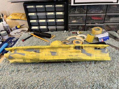
Looking at the tape defining the patterns it is easy to see how difficult to determine the patterns.
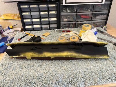
Painted waiting for the paint to remove the tape
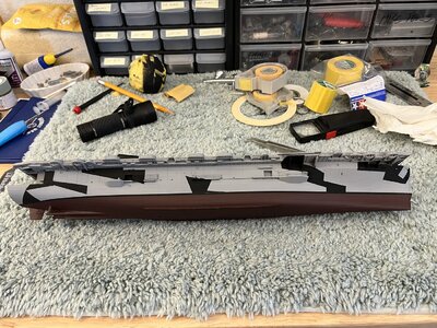
Now with the tape removed it is easy to compare with the drawings and photos. I can see several areas that are not per the drawings and photos. Lucky most of the repair will be adding BK paint and 2 will need the light grey paint over the BK and all the rest will be covered with the dark grey or pale grey.

Looking at the tape defining the patterns it is easy to see how difficult to determine the patterns.

Painted waiting for the paint to remove the tape

Now with the tape removed it is easy to compare with the drawings and photos. I can see several areas that are not per the drawings and photos. Lucky most of the repair will be adding BK paint and 2 will need the light grey paint over the BK and all the rest will be covered with the dark grey or pale grey.
Great work!
All the camouflage completed and onto the wooden deck. I have the Hasegawa wood deck/pe kit to enhance the decks appearance as wood rather than the flash styrene look.
Reading the instructions seemed rather like a simple job. Oh yea you betcha it easy. Removing the deck from the clear plastic sheet seemed easy until I realized that the deck has many openings and as it pealed from the substrate most of the little openings were not cut cleanly and remained with he deck and not left of the substrate. This left me with picking the openings of the plastic surface creating the opening for the pe to be glued. Picking the small openings of the surface left the sides visible showing the light tan color while the surrounding area dyed deck blue. When I got the after overlay that contained the rear elevator the overlay was torn leaving two pieces. Carefully placed both pieces but this still left the torn rough edges shown with the light color along with the torn line. What to do. The dyed deck color was a more green blue than the deck blue paint so I decided that I couldn't correct the areas of light material so I painted the deck with the deck blue paint.
The final result of the deck with paint
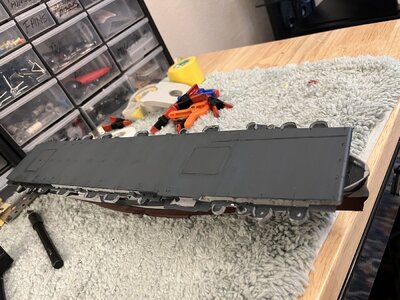
I thought it might be interesting to show you my tape ball of used tape from all the camouflage
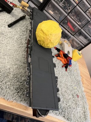
On the deck photo etch which is already black color so no need to paint
Reading the instructions seemed rather like a simple job. Oh yea you betcha it easy. Removing the deck from the clear plastic sheet seemed easy until I realized that the deck has many openings and as it pealed from the substrate most of the little openings were not cut cleanly and remained with he deck and not left of the substrate. This left me with picking the openings of the plastic surface creating the opening for the pe to be glued. Picking the small openings of the surface left the sides visible showing the light tan color while the surrounding area dyed deck blue. When I got the after overlay that contained the rear elevator the overlay was torn leaving two pieces. Carefully placed both pieces but this still left the torn rough edges shown with the light color along with the torn line. What to do. The dyed deck color was a more green blue than the deck blue paint so I decided that I couldn't correct the areas of light material so I painted the deck with the deck blue paint.
The final result of the deck with paint

I thought it might be interesting to show you my tape ball of used tape from all the camouflage

On the deck photo etch which is already black color so no need to paint
I put the photo etch around the rear elevator. Not expecting how this would fit or look. There are two pieces for the elevators that are rectangular rings. The larger ring fits inside the opening surrounding the elevators and the other sits on top of the first. The second ring has the same outside diameter as the larger but the inner diameter is smaller that the first. This leaves a step where the first ring filled the opening and the second ring protrudes very slightly above the deck surface.
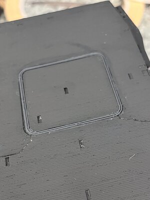
Placing these rings was easier than I first thought. The larger ring sets inside the opening making placement simple. Using a needle dipped in ca a line of ca was drawn around the perimeter of the opening. The photo etch ring just sat atop the ca inside the opening. The second ring was more problematic as I didn't want glue weeping beyond the part edges. Using the needle dipped in ca a ring of ca dots was placed on the first ring. To keep the glued from setting to quickly I used gap filling ca. Placing the second ring was surprisingly easy as the surface tension of the ca aligned the part perfectly to the dot array.
One thing is very noticeable are the tears of the added deck and as has been said many times photo shows all.


