USRC Harriet Lane Model Shipways 1:96 scale circa 1863

Just to add to the confusion note on the engraving of the battle how there are no railings over the gun ports for the 9" Dahlgrens port and starboard aft of the deckhouse. The upper surface of the gun's muzzle is nearly level with the bulwark sheer.
Every time I finish a model that poses questions that require this kind of research I find a load of information that turns some one or more aspects of the build on its' head, POST build! :eek:
Great research and print modeling from Jerry.Thumbs-Up
Pete! Agree 100%
 
Dear Jerry, thanks for coming through AGAIN! I had my suspicions. So, now I have ordered Underhill's "Masting and Rigging: The Clipper Ship and Ocean Carrier" and Crother's "The Masting of American Merchant Sail in the 1850's." Having these references will help me move forward without having to signal SOS every time in the hope that Jerry isn't too busy :p

That is a neat illustration of the action on January 1, 1863. I wonder, however, how far it can be trusted. For example, where is the deck house? What is the structure in the centerline meant to represent? I wonder whether the rail over the Dahlgren howitzers was sacrificed for a better view of the gun. And, something is a little strange about the artists perspective and the foreshortening of certain objects and people. If you compare the objects and people at the starboard gunport with the port gunport, the objects and people to port look a little smaller than they should, at least to me. Kind of a fish-eye distortion without the aid of a camera with a fisheye lens. The howitzer on the port side also looks to be squared in the center of the port. On the other hand, I always thought the shape of the water closets on the model was strange. Was it common in sidewheeler construction to build water closets in such a geometrically complicated design? Although it looks cool, I doubt the model's water closets can be accurate. In this representation the water closets make more sense as structures with right angles. Also, as Jerry indicated, looking at the chains - not a deadeye in sight.

I think Pete mentioned it recently. I know Paul, Grant and others, perhaps countless others, have mentioned it. We're building models. When we're doing it from kits in particular we make a decision to accommodate the kit as designed with a desire for a greater degree of accuracy, or of feeling or both - see Grant's Xebec log. Some call it "bashing". Some call is amendment or improvement or modification. Short of having been there at the time, or having access to the real ship like some lucky people (Constellation, Constitution, HMS Warrior, etc.) there is an ocean of room for inspired interpretation as we make art.

Blessings.
Chuck
Remember, in1863, the illustration in question was taken from a sketch or drawing, maybe based on an eyewitness account firsthand (or 2nd, or 3rd) re-interpreted by the engraver working for (perhaps) "Leslie's Illustrated Weekly". Note that what passeth for the deckhouse has an open back with a sailor halfway out of a companionway from a deckhouse which would be just a fraction of the height of the actual one on the "Harriet Lane.":rolleyes:
All in all the illustration is a pretty good, if not fully faithful, depiction of what somebody had an idea of what the ship actually looked like and her layout. The purpose of the illustration is to give the reader a "ExplosionYOU WERE THEREExplosion" vibe to juice up an already pretty dramatic story and sell newspapers. So, it's probably a fool's errand to go looking for answers to historic detail represented in that picture. ;)
My thought exactly, Pete!
 
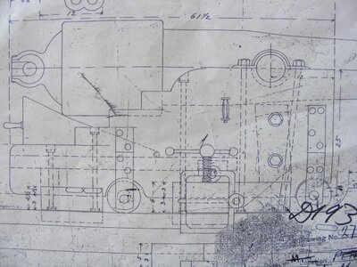
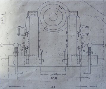
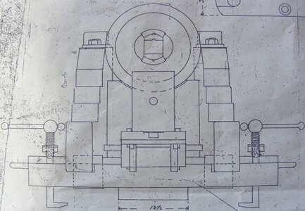
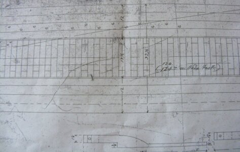
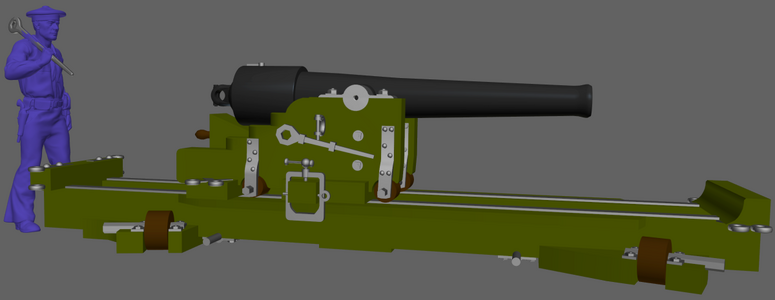
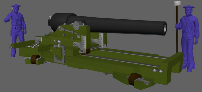
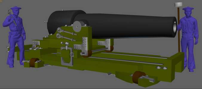
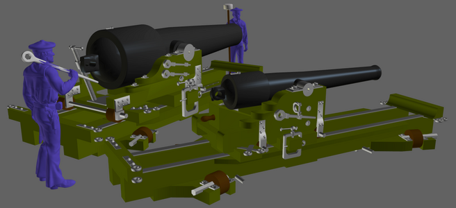
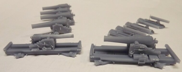
I searched high and low trying to find a drawing or photo of a 30pdr Parrott on a pivot carriage. I found plenty of them on Marsilly carriages, but no pivots.
I saw a drawing years ago when I visited the Constellation, and though I never got a copy from the Archives, I did take some photos, just for interest, since I didn't have a need for them - then.
I finally found those photos on my hard-drive tonight, and got to work rebuilding the model I had slapped together.
(click thumbnail for larger images)
parrotside.jpg parrotfront.jpg parrotrear.jpg parrott_slide.jpg
and came up with this, which isn't quite finished.
30pdr_parrot_pivot20240302a.png

I finished the tubes for all the Parrotts as well, and though it's nothing to do with the Lane, made a 100pdr and a 150pdr Parrott.
parrots20240229a.png
parrott100_20240229a.png parrott150_20240229a.png
30_150pdr_parrotts.pngThe 30pdr and 150pdr together.
 
Good morning, shipmates!

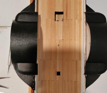
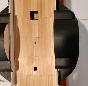
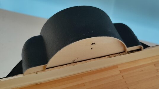
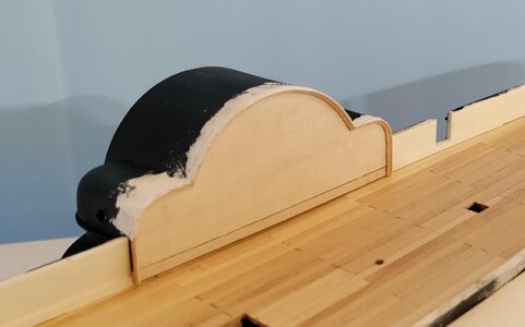
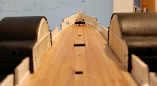
Progress has been a bit slow, but things continue to move forward. I have been focused on the inboard faces of the upper paddle wheel assemblies. In the pictures below, you will probably see that there is a large overlap of the upper assembly over the bulwarks. I attribute this overage to my shoddy craftsmanship. Oh my, Chuck! Why do you say that? I say that because none of the other Harriet Lane build logs indicate that any modeler had trouble getting this right ;)

PWA1.jpgPWA2.jpg
 
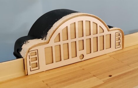
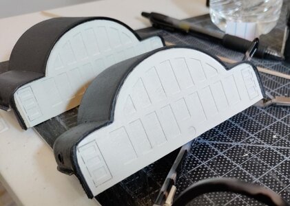
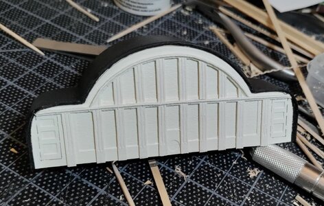
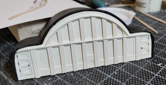
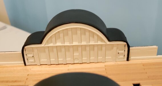
As things turned out this was another mistake. I don't know what was going on with me. Maybe I was too tired AND too impatient. Also I had a very hard time understanding the instructions which said "now remove the bulwark" and attach it to the upper assembly. "Remove the bulwark"???:eek: What the &%#^!@&#!! As I went back to other build logs including BMT's I could see that the instructions were not telling me to cut a huge chunk out of the sides of the ship. Then, looking at the logs and the pictures in the instructions I located the "bulwark" on one of the laser-cut sheets. You wouldn't believe the relief I felt. Back to my mistake. I had wanted to fit the "bulwark" beneath the overhang of the assembly to get a very clean look and to replicate the detailing on the other side. By sanding it flush, I now required myself to butt the "bulwark" against the assembly and to have no overhang and no recess to place the laser-cut card sheet that is meant to help show recessed panels and the doors to the water closets.

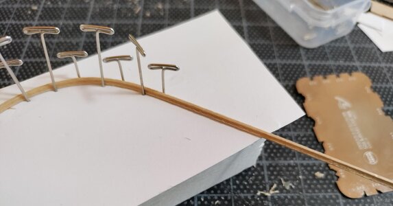
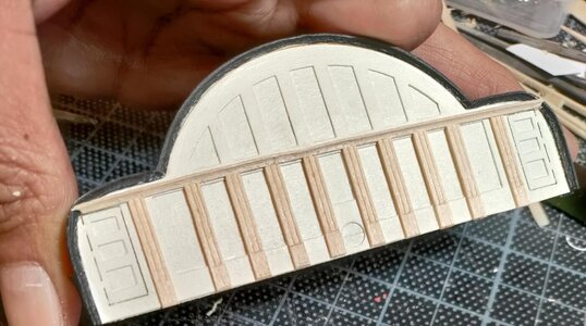
The first picture is what I was going for. The remaining pictures show what I got. First I had to trim the "bulwark" to fit the actual curves of the upper assembly. Then, brainwave, I thought to use a cove molding scraper on some 1/16 square stock to give me the recess I wanted for the card panel.

PWA outboard detail.jpgPWA5.jpgPWA6.jpgPWA8.jpg
 
As things turned out this was another mistake. I don't know what was going on with me. Maybe I was too tired AND too impatient. Also I had a very hard time understanding the instructions which said "now remove the bulwark" and attach it to the upper assembly. "Remove the bulwark"???:eek: What the &%#^!@&#!! As I went back to other build logs including BMT's I could see that the instructions were not telling me to cut a huge chunk out of the sides of the ship. Then, looking at the logs and the pictures in the instructions I located the "bulwark" on one of the laser-cut sheets. You wouldn't believe the relief I felt. Back to my mistake. I had wanted to fit the "bulwark" beneath the overhang of the assembly to get a very clean look and to replicate the detailing on the other side. By sanding it flush, I now required myself to butt the "bulwark" against the assembly and to have no overhang and no recess to place the laser-cut card sheet that is meant to help show recessed panels and the doors to the water closets.

The first picture is what I was going for. The remaining pictures show what I got. First I had to trim the "bulwark" to fit the actual curves of the upper assembly. Then, brainwave, I thought to use a cove molding scraper on some 1/16 square stock to give me the recess I wanted for the card panel.

View attachment 433267View attachment 433268View attachment 433269View attachment 433270
Oy!
The old solid hull original had none of these problems. But then I used the instructions as a rough guide and mostly proceeded as though it was a scratch build. Something I have a bad habit of doing.
 
Here are the pictures of how things finally worked themselves out. Once I got the laser cut card aboard and painted it. I didn't like how it looked. I had to use a make it fit tool (not the hammer, not the sandpaper, the other one) to make it fit in a space that was not as smoothly curving as my beauty shots show. Then I thought, ok let's distract people from looking at how poorly attached the card is by overwhelming their eyes with detail. I hope your eyes are sufficiently overwhelmed. If they aren't don't tell me ;)

BTW the hinges on the water closet doors are bits of 28 gauge annealed steel wire. The door knobs were made with my stone age technology. Take brass pin in pliers left hand. Take Dremel with grinding bit right hand. Grind pin head till looks about right. Dip in Casey's. Rinse with spit. Burnish and glue.:p


PWA9.jpgPWA10.jpgPWA11.jpg
PWA12.jpgPWA13.jpgPWA14.jpg
 
Last edited:
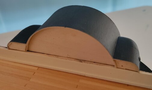
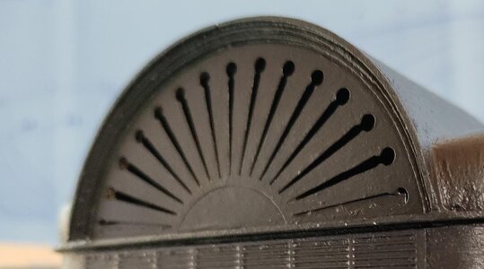
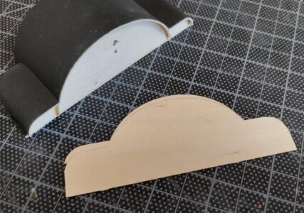
So the plan as of right now is to repeat that process on the portside upper paddle wheel assembly and move to deck house construction. And since the motto of Shangri-la is "go big or go home" I will add a lot of moldings to the deck house ;) Once that's done, I'll shift myself back to the guns:D

Thanks to all of you for following my progress, giving support and being good shipmates. I like you too!
 
The old solid hull kit had moldings and doors etc. printed on card stock. A friend with a great computer graphics program re-engineered everything, made a thumb drive for the laser at the Naval Academy and we cut everything out of card stock including a wraparound molding for the deck house in one piece. If you look closely, you can see a little zig-zag pattern on the edges. But @3/32" =1' you can hardly see it. It's all on the log I posted. On the plans the moldings on the inside walls of the sponsons were not indicated, so I just have the doors. Your hinges and doorknobs look great.
The piece on the outside of the sponsons was a laser cut thin ply piece that came with the kit that I modified and finished as shown. I like the white, the eagles and the louvers. Nice contrast and the eagles (which were etched with the laser and painted by me) add a lot of class. I don't know if that's how she looked at the time. But so, what. Neither does anybody else. The" copper' bottom is mahogany strip with copper paint rubbed in and wiped off. The individual "plates' edges were cut in with a chisel. I got the dark patina I wanted and, again, at that scale, I think it works better than copper tape. It's very subtle and visually to scale.
Of all my models she gets the most attention from the visitors at shows, including the John W. Cannon riverboat. It's their judgement I value most.
I'm really proud of that little model, warts and all.
 
Last edited:
Good morning, shipmates!

Here's a shot of the completed interiors of the upper paddle wheel assemblies and the windlass in the distance. I like the visual texture and the depth of shadows. I think they add to the idea that this is a real ship :D
Deck shot.jpg
 
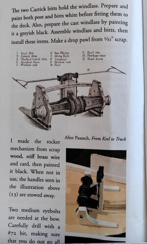
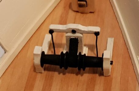
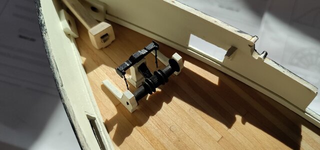
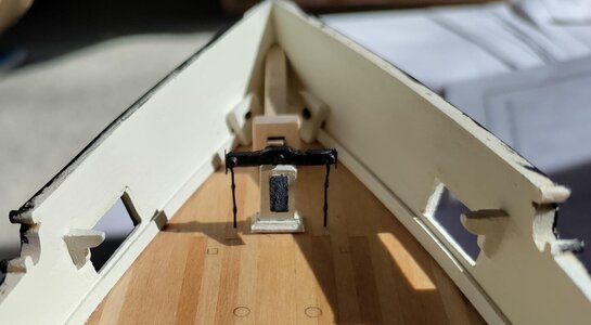
As to the windlass, I wasn't sure how much detail I would add because that area will be covered by an upper foredeck for the Parrott gun. I added a bit more than I stared with just for fun. The instructions show a neat picture of the windlass assembly. Note the apparent height of the Samson post as compared to the width of the Carrick bitts. The as built picture in the instructions shows a nice effort to make the picture come alive. Unfortunately, it does not show (at least I cannot see it) where the purchase rods terminate. As I look more closely at the picture in the instructions, I wonder if I should have scratch built the Carrick bitts . . . .:cool: Maybe I still will. :p Who knows. I may just add the iron straps near the base of each bitt. I am also planning to "bolt" the long arms to the deck.

In the following pictures you'll see the evolution of my windlass assembly. I blackened the windlass with Jax Pewter Black rather than painting it. I also made the Sampson post shorter than the plans and the instructions call for. First, it thought the as built Sampson post was too tall relative to the width of the Carrick bits. Second, the height of my Sampson post had to accommodate the upper deck modification. As you can see, initially I had the crosshead white instead of black. I also left off the round looking lumps on the purchase rods. When I went back to add detail, I painted the crosshead black. The purchase rods are 28 gauge annealed steel wire. I made the round lumps by adding some Titebond II that was almost dry and made sure to add just enough so that gravity didn't pull it out of shape and I blew on it while I changed its orientation to gravity to make sure the round lumps stayed round.

WL instructions.jpgWL2.jpgWL3.jpgWL4.jpg
 
Here are the pictures of how things finally worked themselves out. Once I got the laser cut card aboard and painted it. I didn't like how it looked. I had to use a make it fit tool (not the hammer, not the sandpaper, the other one) to make it fit in a space that was not as smoothly curving as my beauty shots show. Then I thought, ok let's distract people from looking at how poorly attached the card is by overwhelming their eyes with detail. I hope your eyes are sufficiently overwhelmed. If they aren't don't tell me ;)

BTW the hinges on the water closet doors are bits of 28 gauge annealed steel wire. The door knobs were made with my stone age technology. Take brass pin in pliers left had. Take Dremel with grinding bit right hand. Grind pin head till looks about right. Dip in Casey's. Rinse with spit. Burnish and glue.:p


View attachment 433351View attachment 433352View attachment 433353
View attachment 433357View attachment 433355View attachment 433356
Way to go.
 
As to the windlass, I wasn't sure how much detail I would add because that area will be covered by an upper foredeck for the Parrott gun. I added a bit more than I stared with just for fun. The instructions show a neat picture of the windlass assembly. Note the apparent height of the Samson post as compared to the width of the Carrick bitts. The as built picture in the instructions shows a nice effort to make the picture come alive. Unfortunately, it does not show (at least I cannot see it) where the purchase rods terminate. As I look more closely at the picture in the instructions, I wonder if I should have scratch built the Carrick bitts . . . .:cool: Maybe I still will. :p Who knows. I may just add the iron straps near the base of each bitt. I am also planning to "bolt" the long arms to the deck.

In the following pictures you'll see the evolution of my windlass assembly. I blackened the windlass with Jax Pewter Black rather than painting it. I also made the Sampson post shorter than the plans and the instructions call for. First, it thought the as built Sampson post was too tall relative to the width of the Carrick bits. Second, the height of my Sampson post had to accommodate the upper deck modification. As you can see, initially I had the crosshead white instead of black. I also left off the round looking lumps on the purchase rods. When I went back to add detail, I painted the crosshead black. The purchase rods are 28 gauge annealed steel wire. I made the round lumps by adding some Titebond II that was almost dry and made sure to add just enough so that gravity didn't pull it out of shape and I blew on it while I changed its orientation to gravity to make sure the round lumps stayed round.

View attachment 434314View attachment 434315View attachment 434316View attachment 434318
Good evening Chuck. You are owning this. Well done. Cheers Grant
 
Way to go.
Thank you for the compliment, Grant! As you may know, sometimes the closeups show too much detail :eek: Happily, no one will ever be able to get close enough to see how gloppy the paint really is and how rough the wood remained once she's done and under glass. You and my other shipmates are very kind to overlook these things.

Blessings. Peace. Gratitude.
Chuck
 
Back
Top