Greetings, All
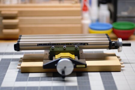
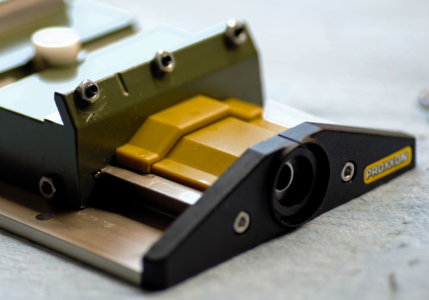
With this thread, I am continuing the discussion about upgrading Proxxon tools (where possible). The subject of today's upgrade is the XY mini table Proxxon's official name is Micro Compound Table KT70. This Micro Compound Table KT 70 gives you the possibility of drilling to precise coordinates or performing small milling operations in conjunction with a bench drill press or a stationary milling machine. This compound table comes packaged with a Proxxon MF70 mill. As stated above, it is designed to be used with some of the other Proxxon devices and can be purchased separately. My Proxxon table was purchased a few weeks ago, at the so-called 'Garage Sale or Flea market, brand new for a fraction of the new one cost. I intend to use it with the drill press stand.
Alright, alright, Jim, you got the deal, but what is the deal with the upgrade? Yea...If you ever use a KT70 table, you will instantly notice that neither the 'Y' nor 'X' direction works smoothly and has some backlash (play). This makes a simple milling task frustrating ( at least to me), and prone to errors due to undesired play, grr. So what we can do to fix it?? Upgrading to thrust Ball Bearings will do the trick. Most of us, MF70 mill owners, will most likely upgrade our compound table within a few weeks of the mill purchase. There are many videos on YouTube showing the upgrade process, so with a purchase of the second table, a decision to made toward tutorial available for SOS members. It will be mostly photos accompanying the text explanations. You absolutely can copy and use the images your way (should you desire), no questions asked.
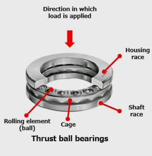
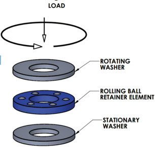
...so, what is the thrust bearing? Thrust bearings are a type of rotary bearing designed to support axial loads and reduce friction between moving parts. They come in several varieties, including thrust ball bearings, which are composed of bearing balls supported in a ring. Thrust bearings are commonly used in low-speed applications to separate a rotating surface from a non-rotating surface, support a rotary table, or absorb the thrust of a propeller. Thrust bearings should never be subjected to radial loads. During operation, the moving components of the machine move with the thrust bearing motion that is intended to allow and support rotation around a fixed shaft or axis. Sounds like this is exactly what we need - to support axial loads and reduce friction between moving parts.
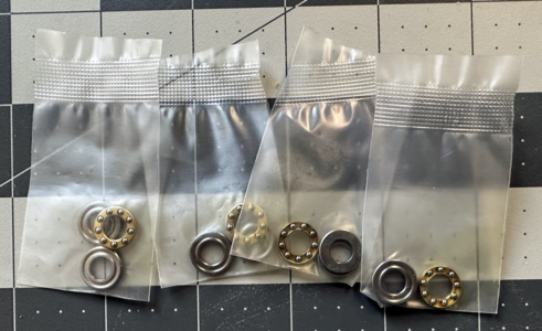
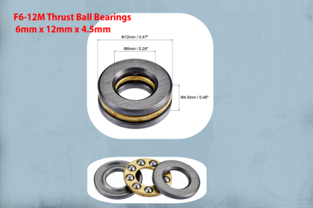
Below, is the photo of exactly the thrust bearing we will be using for our upgrade. This is the label: F6-12M Thrust Ball Bearings 6mm x 12mm x 4.5mm.
You can purchase those on Amazon or Aliexpress (links below)
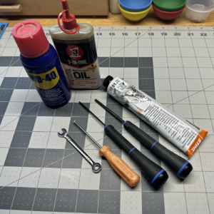
We will also need some tools. Among those is: a 1.5mm hex, Philips screwdriver, and 5.5 and 10 wrenches. We also need some machine oil or grease and WD-40, to clean parts. Step drill bit (not shown).
I assume the bearings are at your disposal, and you have all the necessary tools so we can begin the upgrade process. A few things I'd like to mention before we put our hands dirty. The parts from the X movement and the parts from the Y movement are not interchangeable they are completely different despite the similar look. The X parts are right-handed threads, and the Y is left-handed, when disassembled store them apart from each other.
Part 1: Disasemble
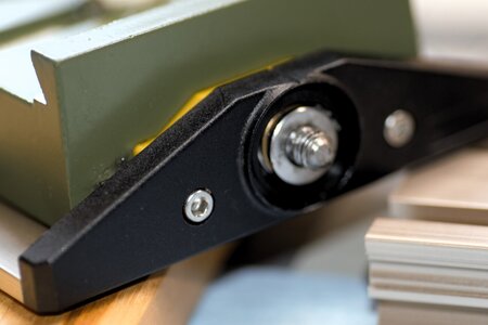
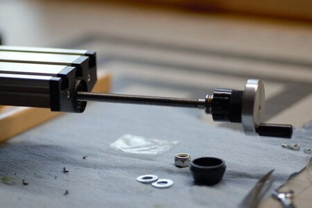
We will start working on the worktable, or the X-axis assembly. Slightly push the sharp object between the black cup cover and the base table to release the cup. Here you can see the nut. Holding the with one hand the wheel and using the 10mm wrench remove the nut.
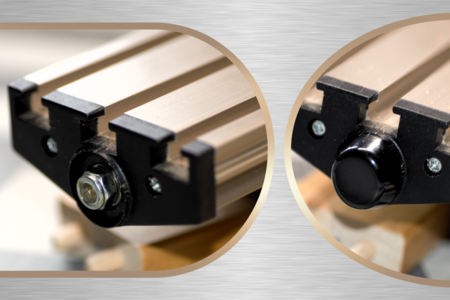
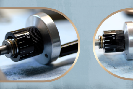
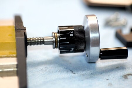
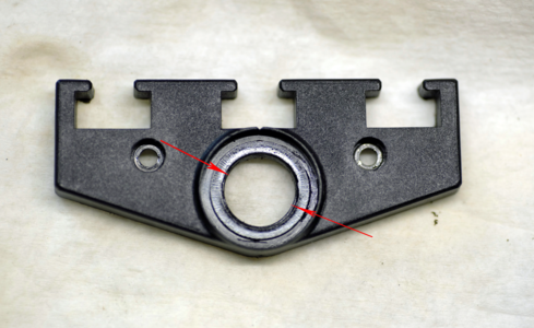
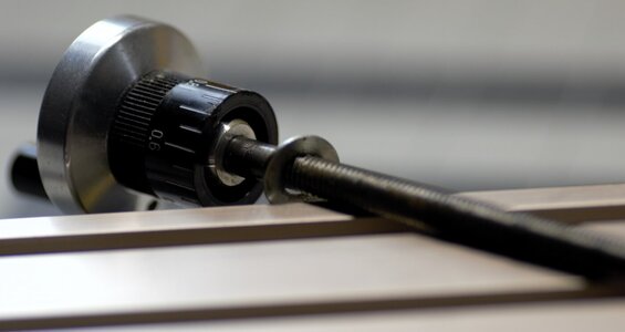
Keep the nut in the cup for safety. The next step is to remove the traversing mechanism. Simply, turn the counter clock on the hand wheel until completely unscrewed and removed. Be careful, and do not touch the dial limb, we don't have to remove it for our tasks. Please note the washer, this is what was used instead of the bearing. You should remove it now and no longer required. At this point, it is a good idea to clean the thread with WD-40. Again, be careful not to remove the dial!
Now, using the Philips screwdriver we can remove both the left and right side plates of the worktable, Once you remove it should be like this.
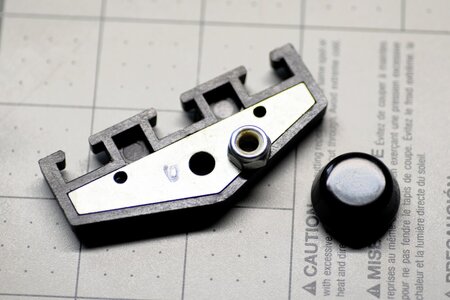
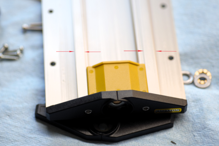
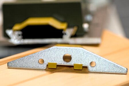
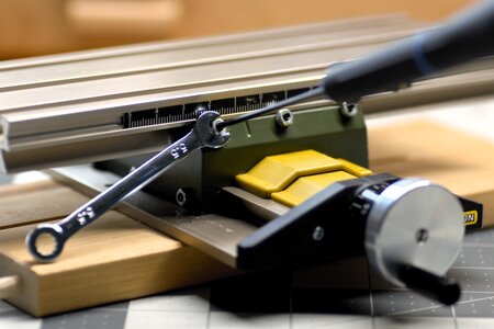
Be familiar with the side plates. There are metal inserts and plastic covers. The inserts could be assembled either way, at your desire. Put them aside for the time being. We are ready to release the worktable. The precision and play are adjusted with set screws. Using the 5.5mm wrench, release three nuts, then using the 1.5 hex release the black set screws. Don't unscrew them completely. A few turns (or so) should do it.
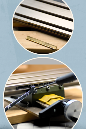
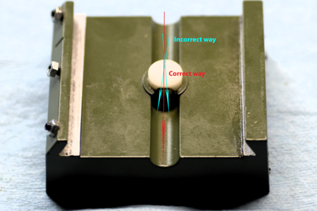
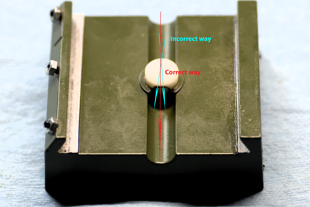
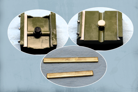
At this point, the worktable should be freely moving back and forth. Carefully slide the worktable until you release the brass plate (top part of the image above). Clean it and keep it safe aside. Well, that's it for the working table. We just disabled the X part of our compound table. Do not remove the graphite (white) nut. The next step is to disassemble the Y part of the table.
It is pretty much the same process. However, it has dustcovers and left-handed thread.
Remove the nut cover by pushing the sharp object between the cup and the side plate. Using the 10mm wrench and holding the hand wheel in one hand unscrew the nut. WARNING!!! This time, please turn the clockwise, recall this is the lefthanded thread.
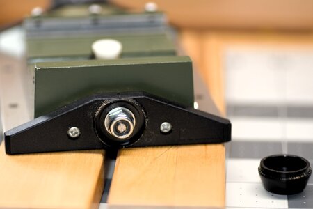
Time to remove the the traversing rod. Again, using the handwheel, turn the clockwise direction until completely removed. Clean the thread using the dump cloth in the WD-40 solution. Now you should have 2 traverse rods. Note one is the shorter than other.
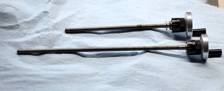
Time to remove the left and right side plates. Same procedure using the Philips screwdriver and 2 screws on each side.
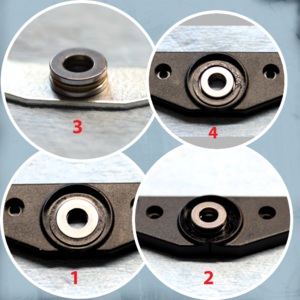
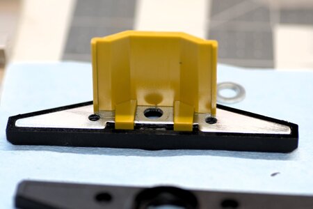
Below is the photo of how the metal insert looks for the Y-part assembly. Pay attention to how they are positioned, it will come in handy when we assemble.
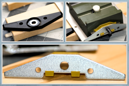
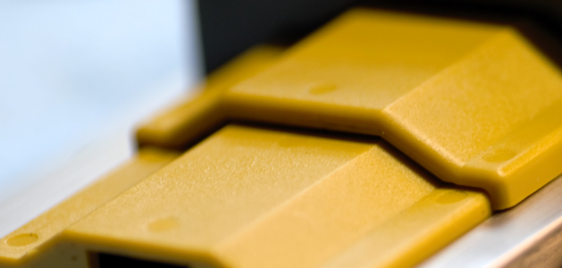
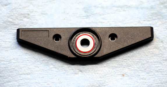
The upper left part of the image depicts the washer used in place of the thrust bearing. Don't forget to remove them, we will no longer require them. Each of the side plates has two dust covers. Please spend a moment and observe how they are attached to the sides using the metal inserts.
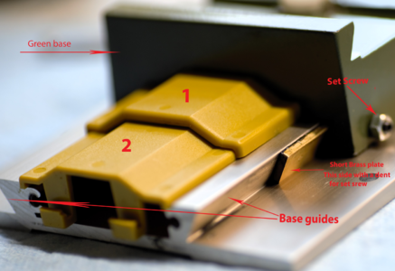
Moving on with the final task, releasing the base. Using the 1,5mm hex and 5.5mm wrench release the set screws, Carefully slide the base (either direction) until you remove the brass part, and clean it from an old oil\grease.
Now you should have all parts separated from the compound table.
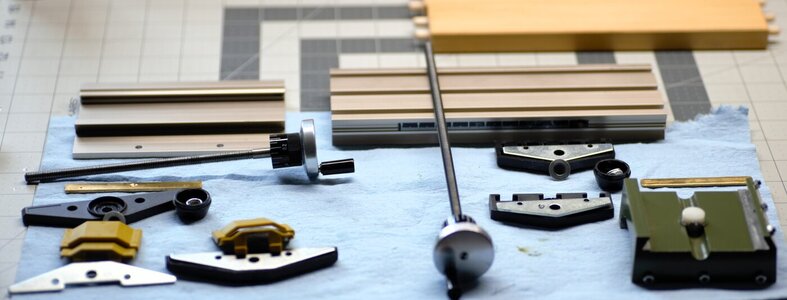
In the above photo, all parts from the Y assembly and on the right side from the X assembly including the base and worktable. Below, is the photo, from the top and bottom sides of the base, NOTE: The bottom side has the black graphite traverse nut, while the top side has white. This is so you can distinguish between the right and left-handed threads. Do not remove them, you can clean them using the brash and WD-40 solution.
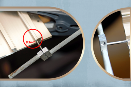
That's it folks, we have completed Part 1 of our tutorial. At this time, you can examine each part closely, and clean them from dirt, dust, and old grease (if any). Play with dust covers to see how they are assembled. Optionally (it is not required, and will not affect the functionality at all), I threaded the base and the worktable to use 3mm hex bolts, instead of regular Philips head screws used by Proxxon.
Oh... it was a lengthy post, I hope you will not have any trouble following the steps outlined. But if you do, I am here, and don't go too far, will be assembling it back so it will work much smoother. Until then so long, and thank you!
With this thread, I am continuing the discussion about upgrading Proxxon tools (where possible). The subject of today's upgrade is the XY mini table Proxxon's official name is Micro Compound Table KT70. This Micro Compound Table KT 70 gives you the possibility of drilling to precise coordinates or performing small milling operations in conjunction with a bench drill press or a stationary milling machine. This compound table comes packaged with a Proxxon MF70 mill. As stated above, it is designed to be used with some of the other Proxxon devices and can be purchased separately. My Proxxon table was purchased a few weeks ago, at the so-called 'Garage Sale or Flea market, brand new for a fraction of the new one cost.
Alright, alright, Jim, you got the deal, but what is the deal with the upgrade? Yea...If you ever use a KT70 table, you will instantly notice that neither the 'Y' nor 'X' direction works smoothly and has some backlash (play). This makes a simple milling task frustrating ( at least to me), and prone to errors due to undesired play, grr. So what we can do to fix it?? Upgrading to thrust Ball Bearings will do the trick. Most of us, MF70 mill owners, will most likely upgrade our compound table within a few weeks of the mill purchase. There are many videos on YouTube showing the upgrade process, so with a purchase of the second table, a decision to made toward tutorial available for SOS members. It will be mostly photos accompanying the text explanations. You absolutely can copy and use the images your way (should you desire), no questions asked.
...so, what is the thrust bearing? Thrust bearings are a type of rotary bearing designed to support axial loads and reduce friction between moving parts. They come in several varieties, including thrust ball bearings, which are composed of bearing balls supported in a ring. Thrust bearings are commonly used in low-speed applications to separate a rotating surface from a non-rotating surface, support a rotary table, or absorb the thrust of a propeller. Thrust bearings should never be subjected to radial loads. During operation, the moving components of the machine move with the thrust bearing motion that is intended to allow and support rotation around a fixed shaft or axis. Sounds like this is exactly what we need - to support axial loads and reduce friction between moving parts.
Below, is the photo of exactly the thrust bearing we will be using for our upgrade. This is the label: F6-12M Thrust Ball Bearings 6mm x 12mm x 4.5mm.

You can purchase those on Amazon or Aliexpress (links below)
We will also need some tools. Among those is: a 1.5mm hex, Philips screwdriver, and 5.5 and 10 wrenches. We also need some machine oil or grease and WD-40, to clean parts. Step drill bit (not shown).

I assume the bearings are at your disposal, and you have all the necessary tools so we can begin the upgrade process. A few things I'd like to mention before we put our hands dirty. The parts from the X movement and the parts from the Y movement are not interchangeable they are completely different despite the similar look. The X parts are right-handed threads, and the Y is left-handed, when disassembled store them apart from each other.
Part 1: Disasemble
We will start working on the worktable, or the X-axis assembly. Slightly push the sharp object between the black cup cover and the base table to release the cup. Here you can see the nut. Holding the with one hand the wheel and using the 10mm wrench remove the nut.

Keep the nut in the cup for safety. The next step is to remove the traversing mechanism. Simply, turn the counter clock on the hand wheel until completely unscrewed and removed. Be careful, and do not touch the dial limb, we don't have to remove it for our tasks. Please note the washer, this is what was used instead of the bearing. You should remove it now and no longer required. At this point, it is a good idea to clean the thread with WD-40. Again, be careful not to remove the dial!

Now, using the Philips screwdriver we can remove both the left and right side plates of the worktable, Once you remove it should be like this.

Be familiar with the side plates. There are metal inserts and plastic covers. The inserts could be assembled either way, at your desire. Put them aside for the time being. We are ready to release the worktable. The precision and play are adjusted with set screws. Using the 5.5mm wrench, release three nuts, then using the 1.5 hex release the black set screws. Don't unscrew them completely. A few turns (or so) should do it.

At this point, the worktable should be freely moving back and forth. Carefully slide the worktable until you release the brass plate (top part of the image above). Clean it and keep it safe aside. Well, that's it for the working table. We just disabled the X part of our compound table. Do not remove the graphite (white) nut. The next step is to disassemble the Y part of the table.
It is pretty much the same process. However, it has dustcovers and left-handed thread.
Remove the nut cover by pushing the sharp object between the cup and the side plate. Using the 10mm wrench and holding the hand wheel in one hand unscrew the nut. WARNING!!! This time, please turn the clockwise, recall this is the lefthanded thread.

Time to remove the the traversing rod. Again, using the handwheel, turn the clockwise direction until completely removed. Clean the thread using the dump cloth in the WD-40 solution. Now you should have 2 traverse rods. Note one is the shorter than other.

Time to remove the left and right side plates. Same procedure using the Philips screwdriver and 2 screws on each side.
Below is the photo of how the metal insert looks for the Y-part assembly. Pay attention to how they are positioned, it will come in handy when we assemble.

The upper left part of the image depicts the washer used in place of the thrust bearing. Don't forget to remove them, we will no longer require them. Each of the side plates has two dust covers. Please spend a moment and observe how they are attached to the sides using the metal inserts.
Moving on with the final task, releasing the base. Using the 1,5mm hex and 5.5mm wrench release the set screws, Carefully slide the base (either direction) until you remove the brass part, and clean it from an old oil\grease.
Now you should have all parts separated from the compound table.

In the above photo, all parts from the Y assembly and on the right side from the X assembly including the base and worktable. Below, is the photo, from the top and bottom sides of the base, NOTE: The bottom side has the black graphite traverse nut, while the top side has white. This is so you can distinguish between the right and left-handed threads. Do not remove them, you can clean them using the brash and WD-40 solution.

That's it folks, we have completed Part 1 of our tutorial. At this time, you can examine each part closely, and clean them from dirt, dust, and old grease (if any). Play with dust covers to see how they are assembled. Optionally (it is not required, and will not affect the functionality at all), I threaded the base and the worktable to use 3mm hex bolts, instead of regular Philips head screws used by Proxxon.

Oh... it was a lengthy post, I hope you will not have any trouble following the steps outlined. But if you do, I am here, and don't go too far, will be assembling it back so it will work much smoother. Until then so long, and thank you!


