Tree Nails on Ships and Ship Models

in my research of the Tecumseth build


the model is 3/8 = 1 foot so it is big enough to show nails, bolts and pegs. The best bet would be to use either brass, silver or aluminum wire. Steel wire will react to the wood and turn it black.
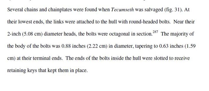
you can see the planking used bolts and clench rings not treenails.
it would be really difficut to replicate the bolt and ring at any scale less than maybe 1/2 inch= a foot


bolt1.JPGbolt2.JPG
 
Last edited:
Because you are building a model of Bonhomme Richard, you may want to consider the existing monograph complemented by at least volume I of the 74-Gun Ship as a source for accuracy regarding fastenings and other subjects. The 74-GS will give you all the information you need, including the description of Nails, spikes, different kinds of bolts, treenails. What all these fastenings were used for, their size, and much more, concerning the time period.
As I always say, go to the source. Furthermore, ships built in Britain, the US will have many similarities but....
G
 
Last edited:
I am well aware of this work which I have in my library, thank you.
My only point was that if you are building a model of a ship built in a French dockyard, you should use the appropriate documentation: especially when the ship has been the subject of extensive study (existing monograph).
It is good to know that there are similarities in the building process and the material used from one country to the other, what is even better is to go to the source. As modelers (regarding French ships), many will have the foundation of the documentation, the French 74-Gun Ship, but will not be able to see the contemporary comparison contained in the book cited above. The building specifications and general practices are described in one document and if one needs to get references to build a model, one will go to the source not the written comparision with the building method in other countries, again, although that comparison has value in the overall knowlege on ship building at the time

In short, the merchant vessel named Duc de Duras, built for French East India Co, the ship later named Bonhomme Richard when it was given to John Paul Jones in 1779, was originally built in France in the Lorient Dockyard (1765): the structure of the vessel, although it was originally a merchant ship, would likely have been built on known / documented French construction specifications and practices at the time.

G
 
Trennels or Treenails

I posted this some time ago - it might help:

Please note these are my own opinions, and should not be read as a hard and fast ‘do it this way’. There isn’t a ‘right way’ as such, and there are many ways of reaching the same result.

First; What are trennels/treenails? Basically, they are wooden pins used to fasten two timbers securely together, rather than using bolts or nails.
The shipwright would auger a hole through the timbers, and then drive in the round wooden treenail using a mallet. The treenail would be very slightly larger than the hole, so a really tight fit was obtained, and if water was taken up by the treenail, it would expand slightly, and make the fastening even tighter. The shipwright would often hammer a wedge into the head of the treenail to expand it even more.
The Chatham dockyard of the period had two men on the books whose sole job was to make the treenails – boring or what!
British practice was to use mainly treenails to fasten planking (hull and deck) with hull planking ends often being fastened using bolts. French practice was to use a mixture of treenails, bolts and nails. I don’t know American practice, but would imagine it was likely to follow British.

Second; On a model, should you bother?
Entirely up to you. Some contemporary models (i.e. actually built in the 1700/1800’s) show the treenails, some don’t.
My own view is that models of 1/48 or larger will benefit from their inclusion, but anything smaller will be perfectly fine without them. It’s all to do with individual perception. Additionally, at 1/48 scale the treenails securing the decks and hull planking would be about 0.018” (18 thou), which is readily achievable, but at 1/96 (say), the treenails would be only 0.009” (9 thou), which I certainly wouldn’t like to attempt.
I only go down to 0.020" or 0.022” because I find it difficult to produce treenails smaller than this using a drawplate, as the wood tends to break below this point, and in addition Franklin, in ‘Navy Board Ship models 1650 – 1750’ states “Strangely enough, scale sized treenails of 1/32” or less always appear to be too small and insignificant on models, and actually look better if a little oversized”

One other thing to think about is the spacing of frames and deck beams; full-size ships have multiple frames quite close together, while most of our models are built on widely spaced bulkheads. I have seen a lot of models where treenails have been employed, but only at bulkhead positions. It looks wrong, and it is quite easy to incorporate additional rows of treenails between the bulkheads, particularly if the hull is double planked

Third; Representation
To my mind, if you’re going to show the treenails, I would prefer to see actual treenails being used. It’s not essential, and treenails can be represented by ‘impressing’, using a large size hypodermic needle filed to a ring-shaped cutter, or by drilling holes and filling with a proprietary wood filler. Franklin, in ‘Navy Board Ship models 1650 – 1750’, notes that impressed treenails are seen on a number of contemporary models. Having said that, I have found that both the above methods are unsatisfactory, as impressing tends to dent the timber below the surface and cause a ‘dimple’, and filling gets messy and suffers from a lack of definition when sanded down.

Fourth; Materials
Most of my models are built using boxwood for the hull, and I prefer to use boxwood treenails. When put in, a boxwood treenail shows an end grain, which takes up a sealer or varnish rather more than the planking, and consequently appears rather darker. This contrast should be subtle, and indeed at more than three feet distant, should virtually disappear.
For this reason, I don’t favour bamboo, as I find the end grain is too prominent and open, and shows rather darker than I would want.
Decks are rather more awkward, as they tend to be of very much lighter coloured timber. On a full-size ship, they would be fastened using treenails made of the same material as the planking itself. My current model of Kingfisher employs Holly as deck planking, and I found it virtually impossible to produce treenails using a drawplate as the timber is relatively soft and breaks. I did try a different technique (Bernard Frolich’s technique) but found the finished result after sanding and scraping the deck was too good, as I could barely see the treenails at six inches!
I again took refuge in Franklin’s ‘Navy Board Ship models 1650 – 1750’ who notes that there is a present-day tendency for modellers to use rather more contrasting timbers than in the past, so I opted for boxwood treenails.
Be aware that commercial kits will often use softer material than boxwood, and the ‘definition’ of the treenails will decrease with the softness of the timber.
Always make up a test panel off the ship before committing yourself to a technique you might later regret using!

Fifth; Techniques
Much of this section has already appeared elsewhere in the forum, but it seems appropriate to include it again at this point, to preserve the continuity of the post:
When I started making treenails, I bought a Vanda-Lay treenail maker, and found it to be quite effective, but liable to break the timber using the smaller 0.025" cutter. This happened quite frequently, at which point I would have to dismantle the thing and poke around with a thin probe in order to get the bits out. There was a further problem in that 0.025" at 1/48 scale equates to about 1.2" full-size, which is a bit large for treenails for planking and decks, which should be about 0.75" (say 0.018" at model size) - It shows! Treenails fixing heavy timbers can however be larger – up to 1.25” (say 0.030”).
I then bought a Jim Byrnes drawplate, which really transformed the game. I use 1.0mm x 1.0mm (about 0.040" square) boxwood stringing which I bought from the Original Marquetry Company in Bristol, UK. This comes in metre long lengths (40") and the grain runs true. It's used by musical instrument makers for the banding on the faces of stringed instruments. I cut a pointed end on a strip, and then pull through the drawplate using a pair of flat-jawed jewellers pliers. I found I can draw down four lengths of stringing to 0.020” in about half an hour - that's sufficient material for about 500 to 600 treenails, allowing for wastage!
The original marquetry site can be found on www.originalmarquetry.co.uk/ , but I'm sure there must be similar outfits over in the states. Incidentally, the same company can also provide black pressure-dyed boxwood stringing, so you can produce all the black treenails for the wales or representations of bolted fastenings!

Points to consider when using a drawplate:
1. Use a proper timber drawplate, such as Jim Byrnes’ – a jewellers drawplate is designed to reduce silver or gold wire to a smaller diameter, but does it by compression, rather than cutting.
2. The wood must be straight grained - if it's at all cross-grained it will break.
3. Mount the drawplate in a solid vice - you can't hand hold.
4. Start in a hole on the drawplate that will just accept the timber.
5. Use every hole in taking the timber down to size - don't be tempted to miss one or two out!
6. Use flat jaw pliers to pull the timber - serrated jaws will bruise the end of the timber and make it break.
7. Pull the timber through the hole steadily and at right angles to the plate.
8. Finally - and I do apologise if this sounds like teaching Grandma to suck eggs - make sure the drawplate is the right way round. The timber should be entered from the side with the hole sizes stamped in.

Actual procedures as follows:
Standard treenailing using hard woods: Make the treenail stock as above, then use a scalpel to make alternate angled and straight cuts along the timber at about 0.150” intervals to give you loads of treenails with a pointed end. Treenails are a bit like socks – you always find them getting lost, to turn up months later where you least expected them! So make plenty.
Mark out the positions of the treenails (Use any of the standard reference works to determine the spacing rules – or tell me if you’re flummoxed, and I’ll add an Addendum), and use a sharp point to make a starter hole. Drill the holes using a drill the same size as your treenails, or a thou or two larger (experiment) Pick up the treenail with forceps, dip in Welbond, and push into the hole until almost flush. When dry, cut off level with the deck using a scalpel, then sand and scrape to a good finish.

Frolich’s Method for softer woods: Used when you can’t pull treenails stock using a drawplate. Take a flat strip of timber, sand down to 0.020”, then cut a strip about 0.150” from the end, across the grain. Take this small strip and cut it along the grain, with the scalpel at a slight angle to make a wedge of material. Take the next cut at the opposite angle, and so on. This will produce individual wedge shaped treenails, which when dipped in glue and inserted in the drilled hole, will slightly deform to a round section and fill the hole. In this instance, experiment with the size of the drilled hole to enable the wedge to fill it.

Sixth; Common errors
Use of oversize treenails – if in doubt, make them small, or leave them out.
Poor marking out – lines of treenails should be straight or it looks wrong.
Using a jewellers drawplate.
Not using a test piece – It’s too late if you start on the hull and don’t like it!


When I posted this article on another forum, I had a response from a member who was having problems, so wrote a bit more about the techniques - might also be of use.


As I started to read your post I immediately thought 'I bet he's got the drawplate the wrong way round!'
Subsequent posts bear that out.
You should be readily able to pull the stringing through the drawplate in one pass and move to the next hole without having to pull it backwards and forwards several times. Possible causes of breakage are: timber slightly cross-grained; not pulling reasonably square to the drawplate; having the drawplate the wrong way round.
Getting the timber to enter the drawplate is initially fiddly, but once you've learned the trick then practice makes it perfect and easy. Mount the drawplate in the vice with the numbers away from you. Put a point on the timber (a single diagonal slash suffices) and introduce it to the hole by leaning over the vice. Grasp the timber immediately behind the head with the flat-jaw pliers held sideways, and hold everything in place by bracing your fingers against the drawplate before gently pushing the point through - The action is more like pulling the timber towards the hole - You should be aiming to have the pliers only about 1/8" away from the drawplate as you start pushing, and keep moving the pliers back to grab more timber as it enters the hole. I can readily pull the boxwood down to 0.018" using this technique - I get a few breakages, but not many these days.
When you grasp the protruding end on the timber, then you will get bruising and splitting of the timber, but I generally find it will keep it's shape for 2 or 3 holes in the plate - just resharpen and carry on - I pull my timbers in 40" lengths, and generally lose about 2" to 3" on the full length due to re-sharpening.
I have a Vanda-Lay cutter, but stopped using it a long time ago, as I genuinely find it much faster and easier to use the drawplate. In addition, the smallest treenail you can produce is 0.024", while most of the treenails I need are 0.018" or 0.020". It doesn't sound much, but it is very noticeable on the model.
Having said that, I can see that the Vanda-Lay would be handy on larger scale boats where you wanted to use Bamboo, as the shorter lengths of cane that you can split off the Bamboo will mean many more passes through a drawplate to produce the same number of treenails.
Keep persevering - you will get there!


That’s about it – Hope it helps!

Ted

Built and posted: Kingfisher/King's Fisher - LSS 1:48
Built and posted: Natterer - Scratch built steam launch
Built and posted:https://shipsofscale.com/sosforums/threads/jaguar-c-type-engine-1-8-scale.5794/post-125786 Jaguar C-type engine

Building: Granado - Bomb Vessel

On hold: Salamandre - Bomb Vessel
Reply
Report Edit
  • Like
Reactions:Clair G, tjbx427, calista and 15 others
 
plate.
8. Finally - and I do apologise if this sounds like teaching Grandma to suck eggs - make sure the drawplate is the right way round. The timber should be entered from the side with the hole sizes stamped in.
A really informative post, thanks. I wonder if you would clarify the entry side of a drawplate, for the wood, as mentioned above. I understood, possibly wrongly, that you put the wood into the flat side of the plate and drew it through and out the larger indented, stamped side.
 
Absolutely correct! - I use a Byrnes drawplate entering the wood from the flat side.

Ted
 
I'm from the camp that sees these as more of a "measles" type look. I've done both ways (with and without) and find that I like the "without" better.
But that's my personal taste.
I will say, and I think it was mentioned above, deck treenails were covered with a "wood plug" and usually of a similar color to the deck (if not the original decking material) and would be very difficult to see at the scales we typically work.
Good luck on whatever you decide!
 
Because you are building a model of Bonhomme Richard, you may want to consider the existing monograph complemented by at least volume I of the 74-Gun Ship as a source for accuracy regarding fastenings and other subjects. The 74-GS will give you all the information you need, including the description of Nails, spikes, different kinds of bolts, treenails. What all these fastenings were used for, their size, and much more, concerning the time period.
As I always say, go to the source. Furthermore, ships built in Britain, the US will have many similarities but....
G
I've download and skimmed through volume I, and already found some interesting "facts" (although in reading the additional information posted above, I'm not sure any single publication can be considered "fact").

Most iron bolts used on French ships are usually square, not round. The heads are not much larger than the bodies, but oftentimes have washers or other materials to enlarge them (a twist of tow wrapped around the head, as also done on deck nails).

Hull and deck bolts and nails were usually countersunk, with the size of the countersink large enough to contain the washers or other material (tow), making the holes much larger than the bolts themselves.

Nails were usually of a length 2.25 times the thickness of the timber they were attaching (this is described in a 5/9 rule where 5/9 of the nail length should be in the beam the timber attaches to. Thus a 4" thick strake would require a 9" long nail. Nails were usually 1/20 their length in thickness, or 0.45" square for this nail. The head would normally be twice the size of the shank, or 0.9" in this case. If no additional washer were required, this would result in a countersunk hold of roughly 1". The largest nails were 15" long, weighed just over a kg each, which works out to about 0.75" square, which confirms to the 1/20 rule.

Long through bolts (as long as 12 feet) through timbers are ranged from 5cm (2"!) at the large end, 4cm at the small end, to as small as 1". Other frame bolts are typically in the 2.7 - 3 cm size.

Treenails are generally used below the waterline and countersunk iron nails above, probably with a plug or dowel for protection against the corrosive sea water. Other areas describe both treenails and countersunk iron nails used below the waterline, iron nails above. Treenails are specified as usually having a diameter at the small end of 1/12 of the thickness of the frame member being attached to, slightly larger at the larger, outer end. I expect this would be in the neighborhood of 1" to 1.25, possibly a bit more."

At least in some areas of the deck, the iron fastenings are countersunk, with tow twisted around, and filled with wood plugs which could be round, square or diamond shape. It seems that this additional step (plug) was not done everywhere, but I personally think that open countersunk holes would not be left to collect dirt and water to continually bear against the iron nails.

In general, for the strakes and decking, the countersinking of holes would result in an apparent hole much larger than the bolt or nail itself, to accommodate the larger head, washer or tow, and but many would approximate the scale 1" we tend to often use on models.

Please excuse and feel free to correct any errors in my quick reading and interpretation of this publication. I've already changed or corrected a couple myself. It was just a quick scan trying to find information pertinent to this discussion.

That's it for now, and certainly sufficient for the start of additional discussion. :)
 
Since I started this thread, I'd like to give my impression so far as to showing fastenings on my subject model, The Bonhomme Richard cross section in 1/48 scale:

It is generally considered possible to create treenail simulations in the 0.5mm (0.020") range, as was done with Uwe's models and others I've seen of this subject. In some cases, as in frame members, a larger connection would seem appropriate. I'm not referring here as to the visibility or construction of the "treenail", only its size and capability in this scale.

Treenails were definitely used in at least some areas of hull strakes, along with countersunk nails in others. The treenail effect we've discussed. If nails are used as with the decking, and if the holes for the nails are countersunk to accommodate flared heads, washers, tor wrapping (and yes, I'm still using that term not knowing what it is but assuming something like heavy fiber with a coating), etc., the countersunk hole diameter would approach the hole diameter for treenails. If that countersunk hole is filled with wood plugs, they would in model scale be indistinguishable from treenails. If not filled, they would be more apparent than treenails, and look different (drilled holes with black pins in the bottom), but I certainly don't want to have 2 different "treenail" representations beside each other.

Uwe's fantastic model, which shows treenails on the deck, done with filler, looks great and is not too "in-your-face", the kit-maker's model shows similar on the outer strakes, which also look fantastic, yet Carlosys model of the same kit has drilled holes only, and to me it is difficult to tell in the photos that they aren't plugs of some sort (except they do contrast a bit more). So I think that any of those representations look very good, and I'll be THRILLED it my model approaches any of them!

As to method, I know without trying that my patience and abilities (and probably years of life remaining) would prevent me making proper treenails and gluing them in place. And the putty method, to me, sounds too messy; I'm hoping the wood I am applying treenails to are finished sanded and to size when the treenails are placed. So I have ordered a set of square mills starting at 0.5mm in size, and intend to mill down a tiny fraction below the surface and rough up that smoothed area. I will experiment doing this before an oil or other finish, and after, to see what difference there is in coloration and texture. I'm hoping the rougher appearance of the same wood will look a bit like end grain, which treenails would be, and may possibly stain/finish a bit darker due to the rougher texture. If this method works for me, making treenails would be no more work than drilling for them, so that would certainly be a time economy.

I also bought some hypodermic needle stock in varying sizes which I intend to try (both these methods were discounted by tedboat, and I am not doubting him, just wanting to see if this is a method that will work for me). My intention is to rough up the "cutting" edge, and "drill" a shallow circle representing the outline of the treenail. Unfortunately, in the smaller sizes, the depressed area outside the treenail will be too large, and may ruin the look, but I'll give that a try too.

Naturally, I'll post my results, here and possibly in a build log should I start one, to get everyone's opinion. But on this particular model, in this particular scale, I think the treenails can "make" the result, and I'll be very disappointed if I can't find a simplified method that is acceptable (not to down other models that don't have them). This is after all a pseudo "ship under construction" which would show many fasteners and other details not normally visible on an operational, painted and weathered ship. Yeah, I know - why are there storage barrels and guns on the deck of a ship under construction? Artistic license, that's why!

This is only MY opinion, at 11:55 tonight, so not only will your mileage vary, but no doubt mine will change over the next days and weeks as well. Please feel free to critique, correct, suggest and discount as your opinion and experience warrant.
 
I really should have started with this, but I am amazed and pleased at the vast information and level of detail responding to me here. It's like I'm going to school again, one that I really enjoy and can never graduate from. I REALLY do appreciate all of your excellent comments and conversation.
 
I'm new at this so bear with me. Has anyone tried "painting" the treenails on the finished ship? I'm thinking that using an acrylic paint pen or Sharpie of the appropriate colour might be something that would work. You could use two or three pens of slightly different colors in a random pattern so that the treenails just barely showed. Just a thought:)

Edit- I went looking for "appropriate" colours and there doesn't seem to be a good choice. I did try a couple of my wife's pens and I think it would work if you could find the right color. I tried taking a picture but my hands are too shaky.
 
Last edited:
A Sharpie will bleed into the wood... I wouldn't try it.
However, there may be a good "pen" that would work if you can find a color that you like... I'm still unconvinced they are needed at this scale or higher.
 
I've download and skimmed through volume I, and already found some interesting "facts" (although in reading the additional information posted above, I'm not sure any single publication can be considered "fact").

Most iron bolts used on French ships are usually square, not round. The heads are not much larger than the bodies, but oftentimes have washers or other materials to enlarge them (a twist of tow wrapped around the head, as also done on deck nails).

Hull and deck bolts and nails were usually countersunk, with the size of the countersink large enough to contain the washers or other material (tow), making the holes much larger than the bolts themselves.

Nails were usually of a length 2.25 times the thickness of the timber they were attaching (this is described in a 5/9 rule where 5/9 of the nail length should be in the beam the timber attaches to. Thus a 4" thick strake would require a 9" long nail. Nails were usually 1/20 their length in thickness, or 0.45" square for this nail. The head would normally be twice the size of the shank, or 0.9" in this case. If no additional washer were required, this would result in a countersunk hold of roughly 1". The largest nails were 15" long, weighed just over a kg each, which works out to about 0.75" square, which confirms to the 1/20 rule.

Long through bolts (as long as 12 feet) through timbers are ranged from 5cm (2"!) at the large end, 4cm at the small end, to as small as 1". Other frame bolts are typically in the 2.7 - 3 cm size.

Treenails are generally used below the waterline and countersunk iron nails above, probably with a plug or dowel for protection against the corrosive sea water. Other areas describe both treenails and countersunk iron nails used below the waterline, iron nails above. Treenails are specified as usually having a diameter at the small end of 1/12 of the thickness of the frame member being attached to, slightly larger at the larger, outer end. I expect this would be in the neighborhood of 1" to 1.25, possibly a bit more."

At least in some areas of the deck, the iron fastenings are countersunk, with tow twisted around, and filled with wood plugs which could be round, square or diamond shape. It seems that this additional step (plug) was not done everywhere, but I personally think that open countersunk holes would not be left to collect dirt and water to continually bear against the iron nails.

In general, for the strakes and decking, the countersinking of holes would result in an apparent hole much larger than the bolt or nail itself, to accommodate the larger head, washer or tow, and but many would approximate the scale 1" we tend to often use on models.

Please excuse and feel free to correct any errors in my quick reading and interpretation of this publication. I've already changed or corrected a couple myself. It was just a quick scan trying to find information pertinent to this discussion.

That's it for now, and certainly sufficient for the start of additional discussion. :)
Hi,
The only "fact" that will remain here is an interpretation of the "facts" included in the book referenced.

In regards to modelship building, anything can be represented anyway one wishes. the main issue is that since we are generally working at a set scale, the scale should be respected for all aspects of the construction, from timbering to fittings. If one chooses to represent fastenings, they should be included with the same respect for scale.
There is no quick way to do this, and the best appearance in the end, will be fastenings (again, if one choose to include them) that are not oversized and if you want to respect some "historical accuracy", you best option is to refer to documentation that is based on historical research: that is what the book referenced is.
One may use an artistic licence, most modelers do in a way anyway. I have never been able to find written conventions a modeler would be able to follow to know what should be included in a model or not, so in the end we see the term "artistic license" used a lot and that is fine. The modeler who wishes to follow the book will often be separated from the rest of the community by being labeled as a "purist". Given the increasing number of modelers these days, those purists have become a very small minority. These people will generally keep working like they used to do, being quite silent about their own work, and being somewhat isolated in there workshop, doing their own thing to their own satisfaction: at least that is my own opinion but it is not a fact.

We should have all realised by now that seeing something enough times on-line or otherwise, often makes that a "fact".

The book referenced above can be used to help the modeler to work within historical data. It is surely not a document telling anyone to represent this or that in a model, it only offers options if one decides to take that information into account.

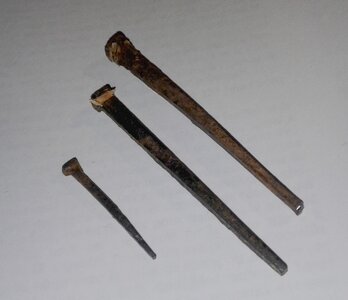
And since this is about fastenings, here are some small nails circa 1850's: the largest one is about 3.5 inches long. These were recoverd from an old house, but since I live in a community where there were quite a few boatyards, I will assume that the same type of nails was used in building local traditional fishing vessels.

20211105_184901.jpg
Although my assumption should not make it a fact.

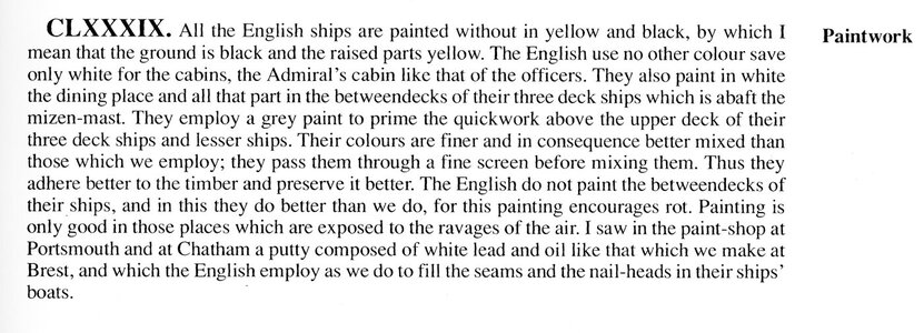
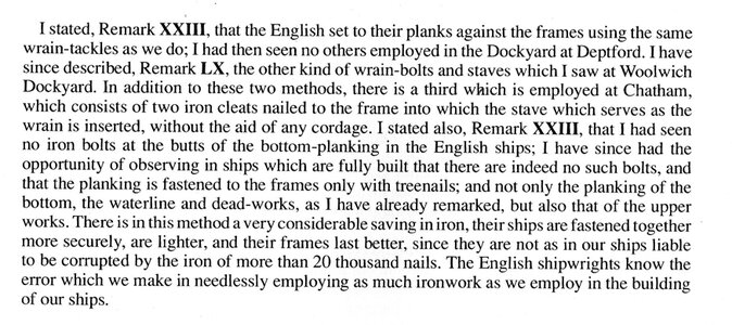
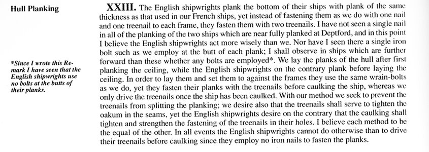
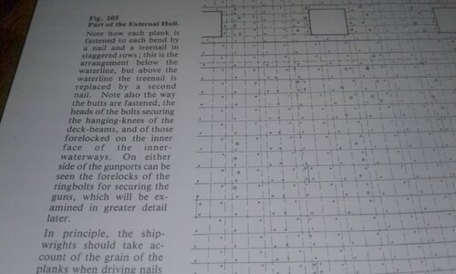
And here is an extract of the doumentaion referenced above: the 74-Gun Ship. So should one elect to fully represent the hull planking fastenings, this is what one would end up with.
Whether one likes the look or not would not make any difference as this representation would be in the realm of personal choice. But.... the option is there to be historically accurate.

20211223_083610.jpg

The book is not a manual telling the modeler what to represent, it is more a multi-volume thesis on naval construction, fitting and other subject related to naval activities. Most monographs written afterward refer the reader to this basic information or knowledge bank.

G.
 
Last edited:
I am well aware of this work which I have in my library, thank you.
My only point was that if you are building a model of a ship built in a French dockyard, you should use the appropriate documentation: especially when the ship has been the subject of extensive study (existing monograph).
It is good to know that there are similarities in the building process and the material used from one country to the other, what is even better is to go to the source. As modelers (regarding French ships), many will have the foundation of the documentation, the French 74-Gun Ship, but will not be able to see the contemporary comparison contained in the book cited above. The building specifications and general practices are described in one document and if one needs to get references to build a model, one will go to the source not the written comparision with the building method in other countries, again, although that comparison has value in the overall knowlege on ship building at the time

In short, the merchant vessel named Duc de Duras, built for French East India Co, the ship later named Bonhomme Richard when it was given to John Paul Jones in 1779, was originally built in France in the Lorient Dockyard (1765): the structure of the vessel, although it was originally a merchant ship, would likely have been built on known / documented French construction specifications and practices at the time.

G
Gilles I do think you hit the nail on the head here.
In a none globelized world then it seems the development of ship building was really country specific or even local. Here in Holland the southern ship builders build their vessels totally different then the builders in the north of holland, shell first vs frame first, and that in a region of only 100 km.

I have recently seen a timeline documentary about the salvage of the spanish ship of the line Triunfante.
For the Spanish navy this was an extraordinary ship build in 1755 build via a fully new design using knowledge stolen from the English.
It was revolutionary for the Spanish to use treenails where they previously used iron nails for the planking of their ships.
So for the Spanish shipbuilders it was normal to use iron nails.
Whereas the English and Dutch seemed to use mainly treenails for planking.

You can find the documentary here.
 
I'm going to highjack my own thread here, rather than start a new one, because it sounds like there are lots of people here who would have knowledge concerning a different subject on the Bonhomme Richard: the Main Mast. In particular, the portion of it visible on this model, from its base to about 11 feet above the upper deck.

Jean Boudroit's book and drawings show the iron hoop spacing and relative overall shape, but shows no attachments nor construction. "The 74 Gunship" drawings show a rubbing paunch starting possibly 8.5' or so above the deck. Cheeks wouldn't be that low. What other details might be on the lower main mast? He seems to indicate some cleats in the drawings.

As to construction of the lower main mast, being almost 3' in diameter, it wouldn't have been just one piece of wood, and at 1/48 scale, it seems appropriate to at least simulate this construction with scored lines. While "The 74" doesn't have any pictures showing this construction, page 22 of Volume 3 "Masts, Sails, etc." has a full description including the Spindle, Coaks, Fore-Side and Aft-Side Trees, etc. The problem is, I can't follow it. "The two sticks forming the side-trees once fayed together are worked on the face which will be fayed to the spindle with its fore-side and aft-side trees; chains of coaks are formed which carefully interlock."
Can someone help with a simpler description or diagram? I love Longridge's book that shows the actual cross section along Victory's mast, but that wouldn't apply here, I imagine.
 
I'm going to highjack my own thread here, rather than start a new one, because it sounds like there are lots of people here who would have knowledge concerning a different subject on the Bonhomme Richard: the Main Mast. In particular, the portion of it visible on this model, from its base to about 11 feet above the upper deck.
Once again, this type of detail is a matter of perswonal choice and one may decide to simplify a bit. You may elect to make the structure of the mast in
7 different elements if you want, assembled without intricate joints, or one piece mast, or anything in between: modelers have the option of using their "artistic license" in a balanced way.
The modelers choice is a balancing act: what should I show, what is practicaly worth including (seen or not seen by the viewer) to achieve some sort of accuracy, only you as the modeler can decide. It is a matter of personal satisfaction balanced with your wishes, your abilities, etc....

I am thinking that you are probably aware of the following and that you may be suffering from a reading overload but...
Mast structure:
Volume III, page 22 does not show the lower mainmast assembly drawings but if you turn to plate XLIII (43), between page 44 and 45, you will find that information including cut views / profiles: the drawings show all the elements assembled step by step to form the structure of the mast: spindle. coaks, fore and aft-side trees and side trees, as well as hoop spacing, etc...
As for the mast fittings, such as rubbing-paunches also called front fish, etc..., such elements are described in the text and you may refer to associated drawings which are usually referenced: example, rubbing-paunches shown in Fig. 240 (page 50), etc...

As for knowledge, not sure what to suggest... no one ever said that it was easy to acquire. it is the result of studies and work: the old fashion way. Only the gifted may get it on the first quick read. Furthermore, text may seem obscur until you move on to the hands-on phase of the construction.

G
 
I have recently seen a timeline documentary about the salvage of the spanish ship of the line Triunfante.
For the Spanish navy this was an extraordinary ship build in 1755 build via a fully new design using knowledge stolen from the English.
It was revolutionary for the Spanish to use treenails where they previously used iron nails for the planking of their ships.
So for the Spanish shipbuilders it was normal to use iron nails.
Whereas the English and Dutch seemed to use mainly treenails for planking.
Hi Marteen,
A very interesting documentary. thanks for the link.
G
 
Once again, this type of detail is a matter of perswonal choice and one may decide to simplify a bit. You may elect to make the structure of the mast in
7 different elements if you want, assembled without intricate joints, or one piece mast, or anything in between: modelers have the option of using their "artistic license" in a balanced way.
The modelers choice is a balancing act: what should I show, what is practicaly worth including (seen or not seen by the viewer) to achieve some sort of accuracy, only you as the modeler can decide. It is a matter of personal satisfaction balanced with your wishes, your abilities, etc....

I am thinking that you are probably aware of the following and that you may be suffering from a reading overload but...
Mast structure:
Volume III, page 22 does not show the lower mainmast assembly drawings but if you turn to plate XLIII (43), between page 44 and 45, you will find that information including cut views / profiles: the drawings show all the elements assembled step by step to form the structure of the mast: spindle. coaks, fore and aft-side trees and side trees, as well as hoop spacing, etc...
As for the mast fittings, such as rubbing-paunches also called front fish, etc..., such elements are described in the text and you may refer to associated drawings which are usually referenced: example, rubbing-paunches shown in Fig. 240 (page 50), etc...

As for knowledge, not sure what to suggest... no one ever said that it was easy to acquire. it is the result of studies and work: the old fashion way. Only the gifted may get it on the first quick read. Furthermore, text may seem obscur until you move on to the hands-on phase of the construction.

G
Thanks for your responses, Giles. I have no interest in constructing the mast in multiple pieces; only in scoring it slightly to indicate where the outer joints would be. Just wanting to add a bit of detail to an otherwise plain area.

As to plate XLIII, my copy of The 74 is only digital, and the plates only go up to XXXVIII, unfortunately. Wonder why they didn't include the rest. Bummer.
 
Back
Top